Ultrafast laser beam shaping for material processing at imaging
plane by geometric phase masks using a spatial light modulator
Zheng Kuang1*, Jiangning Li1, Stuart Edwardson1, Walter Perrie1, Dun Liu2 and Geoff Dearden1
1Laser Group, Centre for Material and Structures, School of Engineering, University of
Liverpool, Brownlow Street, Liverpool, L69 3GQ, UK
2School of Mechanical Engineering, Hubei University of Technology, Wuhan 430068, China
*Corresponding author: [email protected] or [email protected]
Abstract
We demonstrated an original ultrafast laser beam shaping technique for material processing using a spatial light modulator (SLM). Arbitrary beam intensity shapes are created at imaging plane. The size of the shaped beam is approximately 20µm, which is comparable to the beam waist at focal plane. Complicated and time-consuming diffraction far-field phase hologram calculation based on Fourier transformation is avoided. Simple and direct geometric phase masks are used to shape the incident beam at diffraction near-field using a spatial light modulator and then reconstruct at the imaging plane of an f-theta lens. A polished stainless steel sample is machined by the shaped beam at the imaging plane. The shape of the ablation footprint well matches the beam shape.
Keywords: Ultrafast laser, beam shaping, material micro-processing, geometric phase mask,
spatial light modulator
1. Introduction
In the laser two decades, ultrafast lasers have been widely used for high precision and high quality material micro-processing. Materials arranging from metals [1, 2], semiconductors [3], dielectrics [4 - 6] to biological tissues [7, 8] can be processed by ultrafast laser pulses with a very small heat affected zone around the irradiated area. In recent years, the price of commercial ultrafast lasers decreased rapidly and the laser system becomes more and more compact. Nowadays, some type of ultrafast laser systems, such as high repetition rate picosecond fibre laser systems, have been increasingly employed by manufacturing industries.
at focal plane (i.e. far field), the phase modulation to the incident laser beam is complicated. Although algorithms based on time-consuming iterative calculations, such as Gerchberg-Saxton[14, 15], were attempted to solve the issue, the accuracy was still not perfect due to the complexity nature of light diffraction.
In this paper, we demonstrated an original ultrafast laser beam shaping technique for material processing using a spatial light modulator (SLM), which created arbitrary beam intensity shapes at imaging plane. The size of the shaped beam is approximately 20µm, which is comparable to the beam waist at the focal plane. Complicated diffraction far-field phase hologram calculation based on Fourier transformation is avoided here. Simple and direct geometric phase masks applied to the SLM shape the incident beam at diffraction near-field and then reconstruct at the imaging plane of an f-theta lens (f = 100mm). A polished stainless steel sample is machined by the shaped beam at the imaging plane. The shape of the ablation footprint on the sample surface well matches the shape of the beam.
2. Experimental and methodology 2.1 Experimental setup
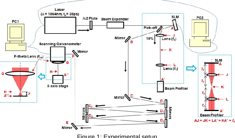
Schematic of the experimental setup is shown in figure 1. A laser beam output (Dia. ≈ 1mm, tp = 20ps, λ =1064nm, R = 200kHz) from a picosecond fibre laser system (Finanium) passed through a half wave plate used for adjusting the linear polarization direction, a beam expander (M ≈ ×5), and illuminated a reflective SLM (Holoeye LC-R 2500), oriented at <10 degree angle of incidence. A pick-off (1%) beamsplitting mirror, placed after the SLM, reflected the beam through two positive lenses (f0 = 200mm) formed 4f system to a CCD camera-based laser beam profiler (Thorlabs) to observe the reconstructed beam shape. After the SLM, the laser beam travelled a long distance by multiple reflections on a series of mirrors, passed through a scanning galvanometer and reached a focusing F-theta lens (f
[image:2.595.92.505.487.730.2]f-θ=100mm). Machining samples were mounted on a three-axis (x, y, z) motion control stage (Aerotech), placed under the F-theta lens.
Figure 1: Experimental setup
When applying a geometric phase mask to the SLM, the beam shaped to the mask geometry near the SLM surface. However, the beam does not maintain the shape when propagating due to the diffraction. The 4f system (AJ = JK = KL = LA’ = f0) between the SLM and the beam profiler was established to reconstruct the beam shape at A to A’.
2.3 Shaping reconstruction at imaging plane of focusing lens
The beam shape at A was also reconstructed at the imaging plane of the F-theta lens, A’’. As shown in figure 1, five extra mirrors, D1 to D5, were added to significantly increase the distance from the SLM to the focusing F-theta lens, i.e. the object distance. The purpose of this was to reconstruct the shape to a small size comparable to the beam waist. The position of the imaging plane A’’ can be calculated, based on the thin lens imaging equation below,
1 𝑢+
1 𝑣=
1
𝑓 (1)
where, u ≈ 15000mm is the object distance, i.e. the distance from the SLM(A) to the F-theta lens(G), f = 100mm is the focal length of F-theta lens and v is the image distance, i.e. the distance from the F-theta lens (G) to the image plane (A’’),
𝑣 = 𝑓𝑢
𝑢−𝑓≈ 100.67𝑚𝑚 (2)
The gap between the focal and imaging plane is:
𝑥 = 𝑓 − 𝑣 = 0.67𝑚𝑚 (3)
The magnification of the image system is M ≈ 1/150. Since the size of the shaped beam at A was approximately 3mm, the size of reconstructed beam at A’’ should be approximately 20µm, which was comparable to the beam waist at focal plane H, and guaranteed sufficient fluence to machine various materials.
3. Results
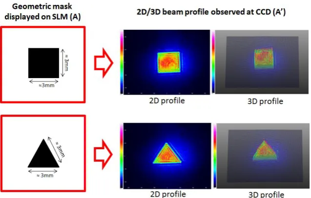
Figure 2: Geometric phase masks, square and triangle, applied to the SLM at A and the correspondent beam profiles observed at A’
Figure 3 demonstrates micrographs of a series of drilling footprints on a polished stainless steel sample. The sample was machined at different heights on the Aerotech stage from the focal plane H to the image plane A’’. The input laser pulse energy Ep was approximately 5µJ, measured before the scanning galvanometer aperture, and the drilling time for each footprint was 0.5s, i.e. 100k pulses per footprint. When machining at the focal plane H (i.e. far field), the footprints were not shaped to the desired geometries at A due to the diffraction. As shown, the shape of footprints gradually changed when approaching the imaging plane A’’, and successfully reconstructed the desired geometries (square and triangle) at the image plane A’’ with a size of ~ 20µm, comparable to the beam waist.
Figure 3: Micrographs of drilling footprints on a polished stainless steel sample, machined at different heights on the Aerotech stage from the focal plane H to the image plane A’’
[image:4.595.144.458.458.597.2]Figure 4: Beam shaped to circle, ring and star geometries. First line: geometric masks applied on the SLM (A). Second line: 3D beam profiles observed by the CCD (A’).Third line:
micrographs of machined footprints at surface of the stainless steel sample (A’’).
4. Discussions 4.1 Shaping quality
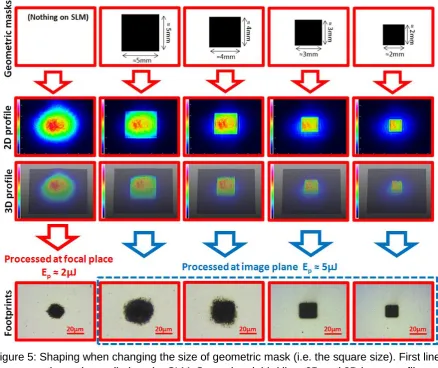
Figure 5 shows the beam profiles observed by the CCD and the footprints machined on a stainless steel sample when changing the size of geometric mask (i.e. the square size). The input laser beam diameter was measured ≈ 6mm. As shown in figure 5, the shaping quality is affected by the size of the geometry displayed on the SLM at A. When applying a larger sized square (e.g. 5mm×5mm or 4mm×4mm), the machined footprint at image plane did not have a good square shape. However, when applying a smaller sized square (e.g. 3mm×3mm or 2mm×2mm), the machined footprint nicely shaped to the square. The reason for this is explained below.
[image:5.595.177.423.70.293.2]Figure 5: Shaping when changing the size of geometric mask (i.e. the square size). First line: geometric masks applied on the SLM. Second and third line: 2D and 3D beam profiles observed by the CCD. Fourth line: micrographs of machined footprints at surface of the
Figure 6: Schematic showing how the shaping is affected by the size of the geometric mask - Upper: The size of geometric mask is too large to shape the high intensity Gaussian beam central part where the fluence reaches the ablation threshold, Lower: The size of geometric
mask is sufficiently small to shape the high intensity central part of Gaussian beam
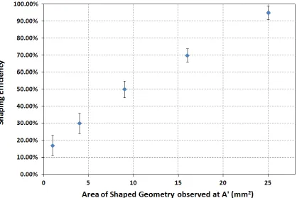
4.2 Shaping efficiency
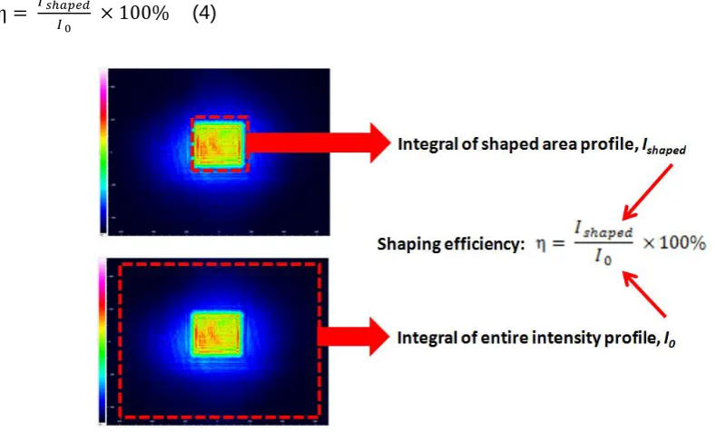
Shaping efficiency was measured by the following method. Firstly, a beam intensity profile was obtained by the CCD at A’ when applying a geometric mask (e.g. a square) at A. The integral of the shaped area profile (Ishaped) and the entire intensity profile (I0) were then
recorded, as shown in figure 7. The shaping efficiency (η) is the ratio between Ishaped and I0,
calculated using the equation below.
η = 𝐼 𝑠ℎ𝑎𝑝𝑒𝑑
[image:7.595.74.469.250.488.2]𝐼 0 × 100% (4)
Figure 7: Shaping efficiency measurement
Figure 8: Shaping efficiency against the area of the shaped geometry observed at A’ by the CCD
As demonstrated above, both shaping quality and efficiency are significantly affected by the size of the geometric mask. In order to machine a nicely shaped footprint on a sample with a high efficiency, the size of the geometric mask should neither be too large nor too small and the most appropriate size significantly depends on the input beam diameter. In our case, the input laser beam diameter was measured ≈ 6mm and the 3mm × 3mm square was found to be appropriate.
5. Conclusions
An original ultrafast laser beam shaping technique for material processing using a spatial light modulator (SLM) was demonstrated in this paper. Arbitrary intensity shapes were created at imaging plane of a focusing lens. The size of the shaped beam is approximately 20µm, which is comparable to the beam waist at focal plane. Complicated far field phase hologram calculation is avoided, while a simple and direct geometric phase masks are applied to the SLM to shape the input beam at near field and then reconstruct at the imaging plane. A polished stainless steel sample was machined by the shaped beam at the imaging plane. The shape of the ablation footprint on the sample surface matched the shaped beam profile.
References
[1] Momma C, Chichkov BN, Nolte S, von Alvensleben F, Tunnermann A, Welling H, et al. Short pulse laser ablation of solid targets. Opt Commun. 1996;129:134–42. [2] von der Linde D, Sokolowski-Tinten K. The physical mechanisms of short-pulse
[3] Sundaram SK, Mazur E. Inducing and probing non-thermal transitions in semiconductors using femtosecond laser pulses. Nat Mater 2002;1:217–24.
[4] Sudrie L, Franco M, Prade B, Mysyrowicz A. Study of damage in fused silica induced by ultra-short IR laser pulses. Opt Commun 2001;191:333–9.
[5] Schaffer CB, Jamison AO, Mazur E. Morphology of femtosecond laser-induced structural changes in bulk transparent materials. Appl Phys Lett 2004;84:1441–3. [6] Osellame R, Taccheo S, Marangoni M, Ramponi R, Laporta P, Polli D, et al.
Femtosecond writing of active optical waveguides with astigmatically shaped beams. J Opt Soc Am B 2003;20:1559–67.
[7] Konig K, Krauss O, Riemann I. Intratissue surgery with 80-MHz nanojoule femtosecond laser pulses in the near infrared. Opt Express 2002;10:171–6.
[8] Watanabe W, Arakawa N, Matsunaga S, Higashi T, Fukui K, Isobe K, et al. Femtosecond laser disruption of subcellular organelles in a living cell. Opt Express 2004;12:4203–13.
[9] Momma C, Nolte S, Kamlage G, von Alvensleben F, Tu¨ nnermann A. Beam delivery of femtosecond laser radiation by diffractive optical elements. Appl Phys A 1998;67:517–20.
[10] R. R. Thomson, A. S. Bockelt, E. Ramsay, S. Beecher, A. H. Greenaway, A. K. Kar, D. T. Reid, Shaping ultrafast laser inscribed optical waveguides using a deformable mirror, Optics Express, Vol. 16, Issue 17, pp. 12786-12793 (2008)
[11] Zheng Kuang, Walter Perrie, Stuart P Edwardson, Eamonn Fearon, and Geoff Dearden, Ultrafast laser parallel microdrilling using multiple annular beams generated by a spatial light modulator, J. Phys. D: Appl. Phys. 47 (2014) 115501 [12] Nicolas Sanner, Nicolas Huot, Eric Audouard, Christian Larat, Jean-Pierre Huignard,
and Brigitte Loiseaux, Programmable focal spot shaping of amplified femtosecond laser pulses, Optics Letters, Vol. 30, Issue 12, pp. 1479-1481 (2005).
[13] N. Sanner, N. Huot, E. Audouard, C. Larat, J.-P. Huignard Direct ultrafast laser micro-structuring of materials using programmable beam shaping, Optics and Lasers in Engineering 45 (2007) 737–741.
[14] R. W. Gerchberg and W. O. Saxton, “A practical algorithm for the determination of the phase from image and diffraction plane pictures,” Optik 35, 237 (1972)