City, University of London Institutional Repository
Citation
:
Uranus, H. P. and Rahman, B. M. A. ORCID: 0000-0001-6384-0961 (2018).
Low-loss ARROW waveguide with rectangular hollow core and rectangular low-density
polyethylene/air reflectors for terahertz waves. JOURNAL OF NONLINEAR OPTICAL
PHYSICS & MATERIALS, 27(3), p. 1850029. doi: 10.1142/S0218863518500297
This is the accepted version of the paper.
This version of the publication may differ from the final published
version.
Permanent repository link:
http://openaccess.city.ac.uk/id/eprint/21014/
Link to published version
:
http://dx.doi.org/10.1142/S0218863518500297
Copyright and reuse:
City Research Online aims to make research
outputs of City, University of London available to a wider audience.
Copyright and Moral Rights remain with the author(s) and/or copyright
holders. URLs from City Research Online may be freely distributed and
linked to.
Low-loss ARROW waveguide with rectangular hollow core and rectangular low-density polyethylene/air reflectors for terahertz waves
Henri P. Uranus
Department of Electrical Engineering, Universitas Pelita Harapan, Jl. M. H. Thamrin 1100, Tangerang 15811, Indonesia.
B. M. A. Rahman
Department of Electrical & Electronic Engineering, City, University of London, Northampton Square, London EC1V 0HB, United Kingdom.
E-mail: [email protected]
Received, Day Month Year
Designing low-loss waveguides for terahertz waves is challenging as most materials are very lossy in this frequency band. Most scientists simply consider transmitting the waves through low-loss air, which however alsohas its own difficulties as index-guiding is not possible. In this paper, we report on the design of low-loss waveguides for terahertz waves and associated results by using a finite element leaky mode solver. These results show that waveguides designed using ARROW (anti-resonant reflecting optical waveguide) approach yield a low combined absorption and leakage loss down to only 0.05 dB/cm for the q-TE00 fundamental mode using realistic values of refractive index at 1 THz operating frequency. The structure employs rectangular hollow-core and low-density polyethylene/air anti-resonant reflecting bilayers, which can be easily fabricated. These results are compared with those of other structures, i.e. a photonic crystal fiber-like structures using the same materials with rectangular holes, which is shown to give a higher loss of 3 dB/cm and a suspended air-core waveguide with TOPAS vein offering a loss of 1 dB/cm.
Keywords: Terahertz waves; terahertz waveguides; finite element method; hollow-core waveguide; anti-resonant reflecting optical waveguide; ARROW; mode solver; leaky modes.
1. Introduction
Terahertz (THz) waves1 or T-rays are electromagnetic waves located in a spectrum gap
between the optics and microwave bands, loosely defined as radiation from 0.1 THz (wavelength 3 mm) to 10 THz (wavelength 30 µm). On the other hand, it has also been defined as millimeter waves in the band from 0.3 THz (wavelength 1 mm) to 3 THz (wavelength 0.1 mm).
Terahertz waves applications include spectroscopy for material characterization, astronomy, imaging, and biosensor1 due to its photon energy that fits well to vibrational
and rotational transition of many molecular cluster. As a non-ionizing radiation, terahertz waves also find applications in imaging of inner layer of fragile archaeological ancient artworks2 and even has been applied to human for full-body scanner3 for airport security.
The availability of high power THz sources open door to nonlinear optics and nonlinear spectroscopy in terahertz regime.4 Four wave mixing nonlinear effect was also employed
for THz generation in fiber.5 Terahertz waves was also proposed for enhancement of
harmonic yield of high harmonic generator for producing attosecond XUV and X-ray pulse.6 For developing terahertz system, sources and detectors are not the only
components. Terahertz absorbers,7 modulators,8 splitters,8 waveguides,5,9 planar circuits,8
etc. were recently reported. In fact, a component that plays role as the basic building block for terahertz system is a waveguide.
Optical waveguides are usually designed for working wavelength in the vicinity of infrared wavelengths, around 1 µm, and the resulting devices have sizes between hundreds of nm to few tens of µm. By considering wavelength scaling rules,10 sizes of
and function, devices for THz regime will have size from tens of µm to few millimeters. Certainly, such larger size devices will be easier to realize by using simpler fabrication technologies within the reach of scientists in developing countries.
However, one of the major problems in developing such guided-wave devices, particularly waveguides for terahertz (THz) band, is that most materials are lossy in this frequency band. Polymers, metals, and semiconductors materials, all suffer from considerable loss in this THz regime. In order to circumvent this, most scientists have considered to guide the waves through the low-loss air within their waveguides, leading to hollow-core structures. However, such scheme has its own difficulties, as air has a low refractive index, hence index-guided waveguiding scheme is not possible and besides that both absorption loss and leakage loss11 are also present. To deal with this, several
schemes have been proposed, e.g. by putting metal wires12 or metal coatings13 as
reflectors, by simply having the reflection from dielectric interfaces,14 photonic crystal
fiber (PCF)-like holey cladding,15 anti-resonant reflection,16 or using the legacy
microwave structures like microstrip structures17 and hollow-core metallic tube,18 etc.
As a close neighbour, devices working in THz regime can also be modeled by using the similar modeling techniques usually used in optics. In this work, we have used a finite element-based leaky mode solver incorporating Bayliss-Gunzburger-Turkel-like transparent boundary conditions which has previously been applied for optics19-20, for
studying THz waveguides. The numerically simulated results show that a hollow-core structure designed with ARROW (anti-resonant reflecting optical waveguide) principles21
with rectangular core and rectangular low-density polyethylene/air reflectors is promising as it yields a low attenuation constant. We have intentionally selected structures with rectangular cross-sectional features since this shape can be more easily fabricated by using relatively simple fabrication technologies, similar to technologies that we have developed for fabricating microfluidic structures22, where patterned sheets are stacked
and thermally bonded. Additionally, these structures support quasi-linearly polarized modes which makes coupling from terahertz sources easier.
2. Method being Used
For this work, we have used a finite-element method (FEM) based on vectorial leaky mode solver utilising the transverse H-field formulation incorporating Bayliss-Gunzburger-Turkel-like transparent boundary conditions (TBC). Detail explanations on the numerical scheme of the mode solver has been given in Refs. 19 and 20.
Since the structures are both leaky and lossy, both properties should be well incorporated into the model. The leaky property is taken into account by proper boundary conditions, which is already built-in in the solver through the TBC, while the lossy property is taken into account by considering the complex refractive index of the materials. Data of complex refractive index of the materials were obtained from data or curves given in published literatures.23-25
3. Design of the ARROW Waveguide
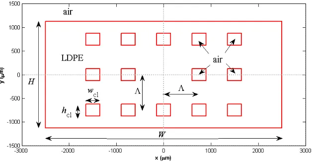
Fig. 1. The cross-section of the proposed ARROW waveguide structure.
3.1. Determining the core size
In order to confine the waves inside the core, a resonant condition was imposed by choosing a proper size, which is both achievable by available fabrication technology and also resonant. To simplify the numerical analyses, we have reduced the structure to a planar system as illustrated in Fig. 2. It should be noted that due to such reduction, the approach is approximative, however, very useful for a quick design.
d
corek
t,corek
t,corej
1,corej
-1,coren
coreInterface -1 Interface 1
...
...
k
t,ar,ik
t,ar,in
ar,iInterface i
Interface i+1
d
ar,i...
j
i,corej
i+1,coreCore
Anti-resonant layer
i
-1
Anti-resonant layer
i
Anti-resonant layer
i
+1
Fig. 2. The round-trip of the transverse waves in the core and the anti-resonant reflecting layers.
-3000 -2000 -1000 0 1000 2000 3000
-2500 -2000 -1500 -1000 -500 0 500 1000 1500 2000 2500
x (m)
y
(
m)
air
air air air air air
air w 2 w 4 h c h 4 h
2 h1
[image:4.595.129.461.440.731.2]For this, the transverse resonance condition requires that the round trip phase change in the core, as illustrated in Fig. 2, should be multiple of 2π, which leads to
2𝑘t,core𝑑core− 𝜑1,core− 𝜑−1,core= 2π𝑀core (1)
with 𝑀core= {1, 2, 3, … }, and kt,core, dcore, φ1,core and φ-1,core are the transverse wave vector
in the core, thickness (wide or height) of the core, and phase shift due to reflection at the interfaces 1 and -1, respectively. It should be noted that the negative sign of the phase comes from choice of positive frequency, where 𝐸 = 𝐸0𝑒𝑥𝑝(𝑖𝜔𝑡 − 𝑖𝛽𝐿) representing
wave moving towards the positive L direction. Figure 2 suggests that
𝑘t,core = 𝑘0Re [√𝑛core2 − 𝑛eff2 ] (2)
with k0 = 2π/λ, ncore, neff, and λ, representing the vacuum wavenumber, core refractive
index, mode effective index, and electromagnetic wavelength, respectively. Notation “Re[]” denotes the real part of a complex quantity. Substituting Eq. (2) into Eq. (1) gives
𝑑core=
2𝑀core+𝜑1,core+𝜑−1,core
𝜋
4Re[√𝑛core2 −𝑛eff2 ]
𝜆 (3)
with the phase shift due to reflection at interfaces 1 and -1 are given by
𝜑𝑙,core= atan {
Im[𝑟𝑙,core]
Re[𝑟𝑙,core]} (4)
with l = {1, -1}, “Im[]” denotes the imaginary part of a complex quantity, and rl,core is the
reflection at interface l for electromagnetic radiation coming from core. These reflection coefficients for the TE and TM polarisations are given by21
𝑟𝑙,core,TE=
𝑘t,core−𝑘t,𝑙 𝑘t,core+𝑘t,𝑙
(5)
𝑟𝑙,core,TM=
𝑛𝑙2𝑘t,core−𝑛core2 𝑘t,𝑙
𝑛𝑙2𝑘t,core+𝑛core2 𝑘t,𝑙 (6)
with kt,l representing the transverse wave vector in the cladding layer next to interface l, while nl is the refractive index of cladding next to interface l.
3.2. Determining the anti-resonant reflection cladding size
For the waves to be confined inside the core, we need to impose the antiresonant condition in each of the cladding reflecting layers. To simplify the analyses, we again reduce the system into 1-D problem, as illustrated in Fig. 2.
The antiresonance condition requires that the round trip phase change in each of the reflecting cladding layer should be odd multiple of π, which leads to
2𝑘t,ar,𝑖𝑑ar,𝑖− 𝜑𝑖,ar− 𝜑𝑖+1,ar= 2π (𝑀ar+ 1
2) (7)
with 𝑀ar= {0, 1, 2, … }, while kt,ar,i, dar,i, φi,ar and φi+1,ar are the transverse wavenumber in
the anti resonant layer i, thickness of the antiresonant layer i, and phase shifts due to reflection at interfaces i and i+1, respectively. By taking
𝑘t,ar,𝑖= 𝑘0Re [√𝑛ar,𝑖2 − 𝑛eff2 ] (8)
with nar,i is the refractive index of the antiresonant layer i, substituting Eq. (8) into Eq. (7) gives the required thickness of the antiresonant layer i
𝑑ar,𝑖=
2𝑀ar+1+𝜑𝑖,ar+𝜑𝑖+1,arπ
4Re[√𝑛ar,𝑖2 −𝑛eff2 ]
𝜆 (9)
𝜑𝑖,ar= atan { Im[𝑟𝑖,ar]
Re[𝑟𝑖,ar]} (9)
𝜑𝑖+1,ar= atan {
Im[𝑟𝑖+1,ar]
Re[𝑟𝑖+1,ar]} (10)
with ri,ar is the reflection at interface i for electromagnetic waves coming from the
antiresonant reflecting layer i toward i-1, ri+1 is the reflection at interface i+1 for waves
coming from anti-resonant layer i toward i+1. These reflection coefficients for the TE and TM21 polarisations are given by
𝑟𝑖,ar,TE=
𝑘t,ar,𝑖−𝑘t,ar,𝑖−1
𝑘t,ar,𝑖+𝑘t,ar,𝑖−1 (11)
𝑟𝑖,ar,TM=
𝑛ar,𝑖−12 𝑘t,ar,𝑖−𝑛ar,𝑖2 𝑘t,ar,𝑖−1
𝑛ar,𝑖−12 𝑘t,ar,𝑖+𝑛ar,𝑖2 𝑘t,ar,𝑖−1 (12)
𝑟𝑖+1,ar,TE=
𝑘t,ar,𝑖−𝑘t,ar,𝑖+1
𝑘t,ar,𝑖+𝑘t,ar,𝑖+1 (13)
𝑟𝑖+1,ar,TM=
𝑛ar,𝑖+12 𝑘t,ar,𝑖−𝑛ar,𝑖2 𝑘t,ar,𝑖+1
𝑛ar,𝑖+12 𝑘t,ar,𝑖+𝑛ar,𝑖2 𝑘t,ar,𝑖+1 (14)
For i=1, the refractive index of the core is used for nar,i-1 and the transverse wavenumber
in core is used for kt,ar,i-1.
3.3. For low-loss quasi-TE mode
For low-loss quasi-TE mode, we expect the E-field to be parallel to the lateral x-axis of the structure and H-field directed in the vertical y-direction as illustrated in Fig. 3. By observing the waveguide in Fig. 3 from A-A’ cut, it shows that we will need core and anti-resonant layers to be optimized for TM polarization in the lateral direction as shown in Fig. 4(a). On the other hand, looking through the B-B’ cut, it shows that the core and anti-resonant layers need to be optimized for TE polarization in the vertical direction, as shown in Fig. 4(b).
E
A
A’
[image:6.595.170.411.478.672.2]B
B’
H
H
H
E
E
E
[image:7.595.130.453.83.216.2](a) (b)
Fig. 4. Illustration on the field directions, (a) TM polarization in lateral, and (b) TE polarization in the vertical directions, required for low-loss quasi-TE mode guiding
3.4. For low-loss quasi-TM mode
Similarly, for a low-loss quasi-TM mode guiding, we expect the E-field to be parallel to the vertical axis and H-field to be in the lateral direction, as shown in Fig. 5. Looking at the waveguide in Fig. 5 from A-A’ cut, it shows that we will need core and antiresonant layers optimized for TE polarization in lateral direction as shown in Fig. 6(a). Meanwhile, looking through B-B’ cut, it shows that we will need core and antiresonant layers optimized for TM polarization in vertical direction as shown in Fig. 6(b).
E
A
A’
[image:7.595.163.404.364.556.2]B
B’
Fig. 5. Illustration on the waveguide optimized for low-loss quasi-TM mode guiding
E
E
E
H
H
H
(a) (b)
[image:7.595.126.446.599.722.2]3.5 Design of low-loss hollow-core ARROW
As discussed in Ref. 21, besides thickness of the antiresonant layers, selection of materials are also important for low-loss hollow-core with rectangular core due to the existence of Brewster’s condition in TM reflection, and high index contrast for high reflection rule of thumb does not apply for TM reflection. The extrema of the TM reflection curve will be located at a point where one of the material has refractive index of 𝑛 = √2𝑛eff. If we consider the neff value of 0.98, it will lead to a refractive index value
[image:8.595.115.472.234.322.2]of 1.39. Table 1 shows refractive indices of several polymers at 1 THz obtained from literatures.
Table 1. Refractive indices of several polymers at 1 THz
Name Refractive index (n) References
PTFE (Teflon) 1.445-i0.0047746 α=2 cm-1, deduced from curve of Ref.
24
PS (polystyrene) 2.08-i0.003581 α=1.5 cm-1, deduced from curve
given in Ref. 25 HDPE (high density
polyethylene)
1.54-i0.0007162 α=0.3 cm-1, deduced from curve
given in Ref. 25 LDPE (low density
polyethylene)
[image:8.595.114.471.362.412.2]1.54-i0.00066845 Re(n) taken from Ref. 23, Im(n) taken from loss model of Ref. 12
Table 2. Proper core size (width or height) of hollow-core ARROW with LDPE wall for neff = 0.98.
Order of resonance
Mcore
Air core size (µm)
TE polarization TM polarization
1 1507.5 -
2 2261.27 753.8
3 3015.05 1507.6
Table 3. Proper thickness of antiresonant layers of hollow-core ARROW with LDPE/air bilayers for neff = 0.98.
Order of antiresonant
Mar
Antiresonant layer thickness (µm)
LDPE Air
TE polarization TM polarization TE polarization TM polarization
0 63.12 63.14 1130.61 -
1 189.39 189.41 1884.39 376.9
2 315.66 315.68 2638.16 1130.70
We have selected LDPE as its real part of refractive index is close to 1.39 and additionally also shows a lower material absorption value. Tables 2 and 3 show the proper core and reflecting layers sizes of air-core ARROW using LDPE/air reflecting layers in both vertical and lateral directions for several values of Mcore and Mar for neff =
0.98. Choosing Mcore=2, Mar=0 (for LDPE) and 1 (for air) gives core size of 753.8 μm and
LDPE/air bilayer thickness of 63.14 μm/376.9 μm in vertical direction, and Mcore=1 and
Mar=0 (for air) and 1 (for LDPE) gives core size of 1507.5 μm and LDPE/air bilayer
thickness of 189.39 μm/1130.61 μm in lateral direction. Rounding up these values gives structure as shown in Fig. 1 with wc=1500μm, hc=750μm, h1=h3=h5=63μm,
h2=h4=376μm, w1=w3=190μm, w2=1130μm, and w4=4520μm. We should note that
thinner LDPE in vertical direction and wider structures in lateral direction were intentionally chosen for the purpose of easier fabrication regarding sheet thickness limitation in thermal bonding method and sheet patterning resolution issues.22
4. Computational Results and Discussions
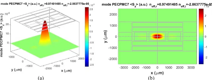
1 THz operating frequency. Figures 7 and 8 show the q-TE00 (with prefix q denoting
quasi) mode, which is the mode with lowest loss in this leaky and lossy structure. The loss of this mode is only 0.05 dB/cm. The longitudinal component of the time-averaged Poynting vector <Sz(x,y)> clearly shows that the near-Gaussian shaped
modal field is well confined inside the hollow-core. Taking advantage of available structural symmetry, the computation was performed only on a quarter of the structure with 15361 quadratic nodes with mesh distribution shown in Fig. 8. Figures 9 and 10 show results for the next lowest loss mode which is q-TM00 mode with α =
0.3 dB/cm. The loss of q-TE00 mode is 5.7 times lower in dB scale than the q-TM00
mode which will make the waveguide to be effectively single mode for a length of 80 cm with multimode rejection ratio (MMRR)26 of 20 dB. We should note that the loss
of q-TM mode is higher than q-TE because for q-TM mode, the TM reflections happen at interfaces in vertical stacks which the structure is thinner in size and also suffer from low reflection coefficients due to the Brewster’s condition, hence the electromagnetic waves can easily leak away. The rectangular structure also induced quasi-linearly polarized modes which will be easy to couple from a terahertz source into the waveguide.
[image:9.595.131.469.301.430.2](a) (b)
(a)
(b)
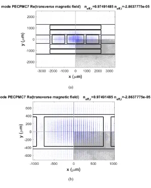
Fig. 8. (a) The transverse component of magnetic field vector ( ˆxHx+yHˆ y) of q-TE00 mode and (b) its
[image:10.595.160.460.87.461.2]close-up distribution in the core.
[image:10.595.196.396.502.635.2](a)
(b)
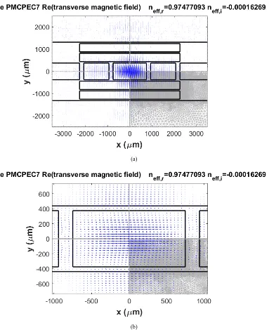
Fig. 10. (a) The transverse component of magnetic field vector ( ˆxHx+yHˆ y) of q-TM00 mode and (b) its
distribution in the core.
For comparison, we have also computed the modes of photonic crystal fiber-like (PCF-fiber-like) structure with same materials and of comparable size which we believe will share the same fabrication challenge as the ARROW structure, and a rather delicate suspended air-core waveguide with TOPAS vein.
[image:11.595.110.493.83.553.2](a)
(b)
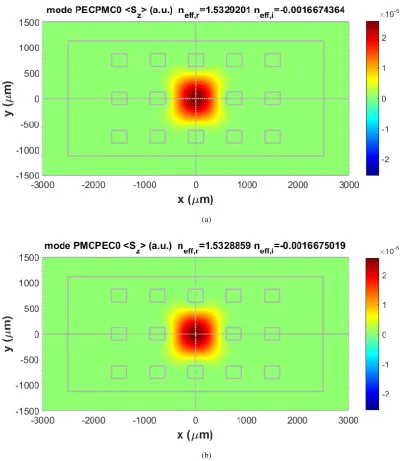
Fig. 12. The longitudinal component of time-averaged Poynting vector for modes of PCF-like structure using rectangular air holes within LDPE host (a) q-TE00, α=3.033 dB/cm, and (b) q-TM00, α=3.033 dB/cm.
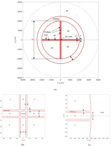
The structure for a suspended square air-core with TOPAS (a nonpolar cyclic-olefin copolymer) vein was taken from Ref. 27. Although the structure is very delicate and hence would be difficult to fabricate, but due to the suspension, the core will be practically surrounded by low index air, hence is expected to give a rather low loss. The structure is shown in Fig. 13 with D = 4 mm, d = 20 μm, Λ = 100 μm, and t = 0.5 mm. The refractive index of air is taken to be 1 while for TOPAS is n = 1.5258 – i 0.0006589 (deduced from Ref. 27) for frequency of 1 THz. The results of the suspended air core structure are shown in Fig. 14. The q-TE00 core mode shows 1
[image:13.595.94.501.84.546.2](a)
(b) (c)
[image:14.595.119.485.101.581.2](a) (b)
(c)
Fig. 14. The q-TE00 mode of the suspended air-core structure with TOPAS vein. (a) and (b) the longitudinal component of time-averaged Poynting vector, and (c). the transverse magnetic field vector around the core.
5. Conclusions
[image:15.595.92.498.83.561.2]the rectangular structure, the proposed waveguide supports quasi linearly polarized modes which will be easier to couple from terahertz sources.
Acknowledgment
This work was supported by Erasmus Mundus LEADERS mobility project financed by European Commission’s EACEA grant number 2014-0855.
References
1. B. Ferguson and X. C. Zhang, Materials for terahertz science and technology. Nature
Materials1(1) (2002) 26-33.
2. P. Daukantas, Cultural artifacts in terahertz light. Opt. Photon. News29(3) (2018) 28-35.
3. Terahertz security body scanner, http://terasense.com
4. J. Hebling, K. L. Yeh, M. C. Hoffmann, and K. A. Nelson, High-power THz generation, THz nonlinear optics, and THz nonlinear spectroscopy. J. Sel. Topics in
Quantum Elect.14(2) (2008) 345-353.
5. A. Barh, B. P. Pal, G. P. Agrawal, R. K. Varsney, and B. M. A. Rahman, Specialty fiber for terahertz generation and transmission: A review. J. Sel. Topics in Quantum
Elect.2(2) (2016) 365-379.
6. L. Feng, W. Li, R. S. Castle, Y. Li, High-intensity attosecond pulse generation by using inhomogeneous laser field in frequency and space. J. Nonlinear Optical Phys. Mat.26(3) (2017) 1750034-1 – 1750034-14.
7. H. L. Dang, V C Nguyen, D. H. Le, H. T. Nguyen, M. C. Tran, D. T. Le, D. L. Vu, Broadband metamaterial perfect absorber obtained by coupling effect. J. Nonlinear
Optical Phys. Mat.26(3) (2017) 1750036-1-1750036-10.
8. A. S. Meijer, G. Berden, D. D. Arslanov, M. Ozerov, R. T. Jongma, W. J. van der Zande, An ultrawide-bandwidth single-sideband modulator for terahertz frequencies.
Nature Photon.10(11) (2016) 740-744.
9. S. Atakaramians, S. Afshar V., T. M. Monro, and D. Abbott, Terahertz dielectric waveguides. Adv. in Opt. and Photonics5(2) (2013) 169-215.
10.J. D. Joannopoulos, S. G. Johnson, J. N. Winn, and R. D. Meade, Photonic Crystals:
Moulding the Flow of Light (Princeton Univ. Press, 2008).
11.H. P. Uranus, Guiding Light by and beyond the Total Internal Reflection Mechanism, Ph.D. dissertation (Univ. Twente, 2005).
12.A. Markov and M. Skorobagatiy, Two-wire terahertz fibers with porous dielectric support. Optics Express21(10) (2013) 12728 – 12743.
13.C. Themistos, B. M. A. Rahman, M. Rajarajan, K. T. V. Grattan, B. Bowden, and J. A. Harrington, Characterization of silver/polystyrene (PS)-coated hollow glass waveguides at THz frequency. J. Lightwave Technol.25(9) (2009) 2456-2462. 14.D. Chen and H. Chen, A novel low-loss terahertz waveguide: Polymer tube. Optics
Express18(4) (2010) 3762-3767.
15.M. Uthman, B. M. A. Rahman, N. Kejalakshmy, A. Agrawal, and K. T. V. Grattan, Design and characterization of low-loss porous-core photonic crystal fiber. IEEE
Photonics J.4(6) (2012) 2315-2325.
16.C. H. Lai, B. You, J. Y. Lu, T. A. Liu, J. L. Peng, C. K. Sun, and H. C. Chang, Modal characteristics of antiresonant reflecting pipe waveguides for terahertz waveguiding.
Optics Express18(1) (2011) 309-322.
17.C. Themistos B. M. A. Rahman, C. Markides, M. Uthman, A. Quadir, and N. Kejalakshmy, Characterization of graphene-based devices for THz systems. in
Terahertz Physics, Devices, and Systems VIII: Advanced Applications in Industry and
Defense, (SPIE, 2014).
18.O. Mitrofanov, R. James, F. A. Fernández, T. K. Mavrogordatos, and J. A. Harrington, Reducing transmission losses in hollow THz waveguides. IEEE Trans.
19.H. P. Uranus, H. J. W. M. Hoekstra, and E. van Groesen, Galerkin finite element scheme with Bayliss-Gunzburger-Turkel-like boundary conditions for vectorial optical mode solver. J. Nonlinear Opt. Phys. and Mat.13(2) (2004) 175-194.
20.H. P. Uranus and H. J. W. M. Hoekstra, Modelling of microstructured waveguides using a finite-element-based vectorial mode solver with transparent boundary conditions. Optics Express12(12) (2004) 2795-2809.
21.H. P. Uranus, H. J. W. M. Hoekstra, and E. van Groesen, Considerations on material composition for low-loss hollow-core integrated optical waveguides. Optics Commun.
260(2) (2006) 577-582.
22.W. Wijaya and H. P. Uranus, Fabrication and characterization of all-plastic flexible microfluidic chip using thermal lamination of patterned sheet, in Proc. The 4th Int.
Conf. on Instrumentation, Communications, Information Technology, and Biomedical
Engineering (ICICI-BME 2015), Bandung, Indonesia (2-3 Nov. 2015), pp. 254-259.
23.Tydex, Terahertz materials, www.tydex.ru.
24.J. S. Jin, G. J. Kim, and S. G. Jeon, Terahertz dielectric properties of polymers. J.
Korean Physical Soc.49(2) (2006) 513-517.
25.M. Naftaly and R. E. Miles, Terahertz time domain spectroscopy for material characterizations. Proc. of The IEEE95(8) (2007) 1658-1665.
26.H. P. Uranus, Theoretical study on the multimodeness of the commercial endlessly single-mode PCF. Opt. Commun.283(23) (2010) 4649-4654.