UNIVERSITI TEKNIKAL MALAYSIA MELAKA
DEVELOPMENT AND OPTIMIZATION OF PORTABLE
VACUUM CLAMPING
This report submitted in accordance with requirement of the Universiti Teknikal Malaysia Melaka (UTeM) for the Bachelor of Manufacturing Engineering
Technology (Process & Technology) (Hons.)
by
NABIL HAIKAL BIN ABDUL RAHMAN B071410134
920922-14-7095
TAJUK: Development and Optimization of Portable Vacuum Clamping
SESI PENGAJIAN: 2017/18 Semester 1
Saya NABIL HAIKAL BIN ABDUL RAHMAN
mengaku membenarkan Laporan PSM ini disimpan di Perpustakaan Universiti Teknikal Malaysia Melaka (UTeM) dengan syarat-syarat kegunaan seperti berikut:
1. Laporan PSM adalah hak milik Universiti Teknikal Malaysia Melaka dan penulis. 2. Perpustakaan Universiti Teknikal Malaysia Melaka dibenarkan membuat salinan untuk
tujuan pengajian sahaja dengan izin penulis.
3. Perpustakaan dibenarkan membuat salinan laporan PSM ini sebagai bahan pertukaran antara institusi pengajian tinggi.
4. **Sila tandakan ( )
SULIT
TERHAD
TIDAK TERHAD
(Mengandungi maklumat yang berdarjah keselamatan atau kepentingan Malaysia sebagaimana yang termaktub dalam
AKTA RAHSIA RASMI 1972)
(Mengandungi maklumat TERHAD yang telah ditentukan oleh organisasi/badan di mana penyelidikan dijalankan)
Alamat Tetap:
LOT 6260, LORONG 7, PERMAI 1 34100 SELAMA,
PERAK
Tarikh:
________________________
Disahkan oleh:
UNIVERSITI TEKNIKAL MALAYSIA MELAKA
BORANG PENGESAHAN STATUS LAPORAN PROJEK SARJANA MUDA
Cop Rasmi:
DECLARATION
I hereby, declared this report entitled Development and Optimization of Portable Vacuum Clamping is the results of my own research except as cited in references.
Signature : ……….
APPROVAL
This report is submitted to the Faculty of Engineering Technology of UTeM as a partial fulfillment of the requirements for the degree of Bachelor of Manufacturing
Engineering Technology (Process And Technology) with Honours. The member of
the supervisory is as follow:
i
ABSTRACT
ii
ABSTRAK
iv
DEDICATION
As a token of appreciation, I dedicate this thesis to both of my parents, Mr. Abdul Rahman Bin Hj Sidek and Mrs. Huzaimah Bt Abdul Rashid whose word of encouragement and always give positive vibes whenever me in depress and not to forget all my siblings that always support and give encouragement to proceed with thesis. I also dedicate my dissertation to all my friends that support and contributed some of the ideas for this research. Thank you for everything. Lot of love my family-rangers.
v
ACKNOWLEDGEMENT
Alhamdulillah. Firstly, I would like to thanks to Allah S.W.T for His blessing to enable for me to complete this thesis in time. Special appreciation to my supervisor, Dr Norfariza Bt Ab Wahab for guiding and giving advice to me throughout this thesis carried out.
Besides, not to forget technician who always help me solve some of the problem while doing my thesis who are Mr Azimin, Mr Zulkifli, Mr Hisyam, Mr Basri and all JTKP technician.
vi
TABLE OF CONTENTS
DECLARATION I
APPROVAL II
ABSTRACT I
ABSTRAK II
DEDICATION IV
ACKNOWLEDGEMENT V
TABLEOFCONTENTS VI
LISTOFTABLES IX
LISTOFFIGURES XI
CHAPTER 1 1
INTRODUCTION 1
1.1 Background 1
1.2 Problem Statement 2
1.3 Objectives 2
1.4 Project Scope 2
CHAPTER 2 4
LITERATUREREVIEW 4
2.1 Introduction 4
2.2 Machining Process 4
2.2.1 Conventional machining process 7
2.2.2 Advanced machining process 7
2.3 Milling Machine 8
2.3.1 Methods of Milling 8
2.3.2 Types of Milling 10
2.3.3 Cutting tool of Milling 12
vii
2.4.1 Vacuum 15
2.4.2 Atmospheric air 16
2.4.3 Vacuum pumps 16
2.4.4 Vacuum clamping 17
2.5 Effect of Parameters 17
2.5.1 Feed rate 18
2.5.2 Cutting Speed 18
2.5.3 Depth of Cut 18
2.5.4 Dimensional accuracy 19
2.5.5 Temperature 19
2.5.6 Chip formation 19
CHAPTER 3 20
METHODOLOGY 20
3.1 Introduction 20
3.2 Part Identification 22
3.2.1 Problem Statement 22
3.2.2 Existing Design of Vacuum Clamping 23
3.3 Optimization of Design Vacuum Clamping 24
3.3.1 Machining 25
3.4 Validation of Product 30
CHAPTER 4 31
RESULTANDDISCUSSION 31
4.1 Introduction 31
4.2 Finish Product 31
4.2.1 Machining process 35
4.2.2 Advance machining process 36
4.2.3 Part Assembly 37
4.3 Surface Roughness 40
viii
4.3.1 Comparison on depth of cut 46
4.4 Clamping Force 48
CHAPTER 5 49
CONCLUSIONANDRECOMMENDATION 49
5.1 Introduction 49
5.2 Summary of this research 49
5.3 Limitations 50
5.4 Future Investigation 51
REFERENCES 52
APPENDICES 54
APPENDICESA 55
APPENDICESB 59
APPENDICESC 60
ix
LIST OF TABLES
Table 3.1 Machine, cutting tool and material used 27 Table 3.2 Machine, cutting tool and material used 28 Table 3.3 Machine use, part needed and component 29
Table 3.4 Cutting parameter 30
Table 4.1 : Machining process 35
Table 4.2 : Cutting tool and process 36
Table 4.3 Cutting parameter for first experiment 42 Table 4.4 Cutting parameter for second experiment 43 Table 4.5 Comparison between conventional vise and vacuum clamping 44
x
LIST OF CHARTS
Chart 4.1 Line graph of conventional vise & vacuum clamping 45
xi
LIST OF FIGURES
Figure 2.1 Turning process 5
Figure 2.2 Milling process 5
Figure 2.3 Drilling process 6
Figure 2.4 Index milling 9
Figure 2.5 Gang milling 10
Figure 2.6 Gang milling 11
Figure 2.7 Horizontal milling 11
Figure 2.8 Universal milling 12
Figure 2.9 Cutting end mill 13
Figure 2.10 Face end mill 14
Figure 2.11 Slot mill 14
Figure 3.1: Vertical milling machine 20
Figure 3.2: Flowchart of Methodology Process 21
Figure 3.3: Previous Project Design 22
Figure 3.4: Dimension for top view 23
Figure 3.5: Dimension for base 23
Figure 3.6: conceptual design 24
Figure 3.7: exploded view 25
Figure 3.8: Body part 26
Figure 3.9: Base part 28
Figure 3.10: All part is assembled 29
Figure 4.1 : Dimension of latest design 31
Figure 4.2 : Latest design using CATIA V5 32
Figure 4.3 : Finish Product 32
Figure 4.4 : Product was apply on milling table 33 Figure 4.5 : Advance machining process by using CATIA V5 33 Figure 4.6 : Process machining by using CATIA V5 34
Figure 4.7 : Body and Base part 34
xii Figure 4.9 Vacuum clamping attached to milling table 37
Figure 4.10 Clamping kit 37
Figure 4.11 Vacuum pump connected to jig 38
Figure 4.12 O-ring sealing cord apply to vacuum clamping 38
Figure 4.13 Size of O-ring sealing cord 39
Figure 4.14 Example of sample workpiece 40
Figure 4.15 Cutter flat end mill 40
1
CHAPTER 1
INTRODUCTION
1.1 Background
A vacuum is the state in a space which is free of matter. In practice, we already call it a vacuum when the air pressure in a space is less than that of the atmosphere.
Vacuum clamping is one of the new clamping method in recent years. Vacuum clamping systems can used in the wood, plastics and non-ferrous metals industries for quick, simple machining. They can be compatible with CNC machine tools or conventional machines. Vacuum technology is used in connection with special handling systems for example in order to fix an aluminium plates and machine it from all sides. This increases productivity and cost-effectiveness. The fixing does not cause any damage to the workpiece and no laborious. The latest clamping systems allow attachments of the various sizes and shapes to be exchange in a very short time, thus facilitating flexible handling of a wide range of workpiece shapes.
In vacuum clamping, an underpressure is generated under the workpiece being clamped, i.e. a pressure is differential is created which presses the workpiece against the clamping plate.
2
1.2 Problem Statement
In milling machine, fixtures system is very important to hold, support, and clamp workpiece during machining but there are several problem in using clamp in milling machine. Firstly there is no default shape material that can be apply as default vise for conventional milling machine. Second, there is no exact value of force for clamping material during machining. Too much force acting on workpiece may damage the workpiece especially for soft material. Beside that, there can cause incident for safety issue if wrongly control the machine. Colliding with the vise can cause damage to the cutting tools and also dangerous to the operator. Lastly, the time taken for initial setup each operation of milling machine . The clamping process alone take too much time in whole milling cutting process operation.
1.3 Objectives
The project objective that have been determined are:
1. To modify the vacuum clamping method for milling machine 2. To optimize the design of the vacuum clamping
3. To analyze the result of vaccum clamping in the term of surface roughness with current clamping jig.
1.4 Project Scope
Scopes for this project is based on objectives that have stated and there are the several scopes that will be carrying out :
1. Design of the improvement vacuum clamping is based on conventional milling machine at JTKP laboratory
3 3. The result of surface roughness will be conducted to evaluate the result of
4
CHAPTER 2
LITERATURE REVIEW
2.1 Introduction
In chapter two, literature review is a text of the works of others people which can pave the way for a better research. It can help to giving a relevance research for a particular topic. This chapter is consist of machining process, milling process, clamping method and effect of cutting parameter
2.2 Machining Process
Machining is manufacturing process of removing the undesired or unwanted material from the workpiece or job or component to produce required shape using cutting tool. This can be done by manual process or by using machine called machine tool (Singh, 2006). Most of the engineering components such as gears, bearings, clutches, tools, screws and nuts required dimensional and form accuracy and good surface finish designed for serving their purposes. Machining process allocated into three process which is turning, milling and drilling. There are others process such as broaching, boring, sawing and shaping that involved under group of miscellaneous.
5 Figure 2.1 Turning process [ retrieved from
http://article.sciencepublishinggroup.com/html/10.11648.j.ijmea.20160403.12.html ]
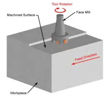
Milling is the method of machining horizontal, arched, or unequal edges by nourishing the workpiece in contrast to spinning cutter covering a figure of cutting sides. The typical mill contains mostly of motor-powered driven spindle, which stands and rotations the milling cutter, and reciprocating adjustable workbench, which stands and feeds the workpiece.
Figure 2.2 Milling process [ retrieved from
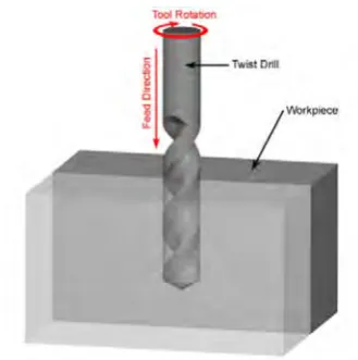
[image:21.595.224.409.485.657.2]6 Drilling is a process of creating a rounded hole by way of eliminating a volume of metal from the work by cutting instrument called drill. A drill is a rotating end-cutting instrument by single or additional end-cutting lips and typically one or more flutes for the passage of chips and the admission of cutting fluid. A drilling machine is a mechanism tool created for drilling holes in metals. It is one of the record important and versatile machine gears in a factory. In addition drilling curved holes, a lot of other processes can also be completed on the drilling machine such as counter- boring, countersinking, sharpening, reaming, and lapping (Singh, 2006).
Figure 2.3 Drilling process [ retrieved from
http://www.custompartnet.com/wu/drilling ]
7
2.2.1 Conventional machining process
Conventional Machining Methods frequently eliminate material in the technique of chips by put on forces on the workpiece through a section formed cutting device that is stiffer than the workpiece under machining situation.
Conventional machining needs a instrument that is tougher than the workpiece that is to be machine. This device penetrates into the workpiece intended for a certain depth of cut. A relative motion between the tool and workpiece is responsible for form and generation cutting to produce the required shape, dimensions, and surface quality. Such a machining arrangement includes all machining by cutting and mechanical abrasion processes. The absence of tool hardness or contact with the workpiece makes the process traditional (Hassan Abdel-Gawad El-Hofy, 2014).
2.2.2 Advanced machining process
Advanced manufacturing processes is defined as a group of processes that remove excess material by various techniques involving mechanical, thermal, electrical or chemical energy or combinations of these energies but do not use a sharp cutting tools as it needs to be used for traditional manufacturing processes.
The application of nontraditional machining (NTM) methods has paved the way for new developments in machining hard to-machine and advanced materials, both now and in the future. The use of these NTM processes is increasingly requested on the shop floor (Chakladar and Chakraborty, 2008).
8
2.3 Milling Machine
Milling machines come in a wide variety of types such as universal, horizontal, vertical and drum. Each of these have their own unique features and used for various operations. In milling machine, there are many process parameters like spindle speed, feed rate, depth of cut, coolant, tool geometry etc. which affected on required quality parameters (Patel, 2015). The main advantage of the milling machine is that it can be used to perform literally any operation with a great degree of accuracy and hence it is an indispensable machine for any workshop.
Some advantages of this technique include lower machining forces, better penetration of lubricant into cutting zone, lower cutting temperature, higher tool life, higher machining accuracy, improvement of surface quality, burrs of lower height, and better chip formation (Janghorbanian et al., 2013)
2.3.1 Methods of Milling
There are various type of method that can be use in milling. Each of these method apply different specifications and functions. Given below are show a few of the most commonly used milling methods in the manufacturing industry.
Single piece milling is method that used for milling single job work which is held on the milling machine. It is important to note that the piece has to be worked in a single machine cycle for it to be classified under this category of milling methods. String milling is quite similar to single piece milling but the only difference being that instead of single piece there are several parts which is simultaneously fixed and are worked upon.