Abstract: In this work the DC-DC forward converter is proposed. The forward converter system nonlinear dynamic performance is present, as it works in switch-mode. Besides, it is revealed to significant inequality which may take this system during the nominal conditions, due to fluctuations on the load or on the line voltage at the input. Traditional converters like, boost converters, switched- inductor converters, switched -capacitor converters etc. are restricted because of at most duty cycle (unity). Fundamentally transformer is introduced to improve the voltage and also it gives the benefits of supplying power to various loads, therefore it is further acceptable for different DC power applications. Examination at open control of the suggested converters are described in this work and we investigate the equations of a forward converter and propose a design for components and also simulated two and three switches forward converter. The suggested converter (FC) has been verified theoretically by simulating it in MATLAB Simulink.
Keywords: converters, three switch, two switch ,inductors, power applications.
I. INTRODUCTION
An industrial and some commercial applications need DC power. An Electronic DC Converter that transforms Direct Current from low/high level to another. With isolated DC converters, level of DC voltage is changed to another level by exchanging the input for the time being and delivering that energy to the output at a various voltage level. Majorly these converters are used in easily movable electronic gadgets like computers and cellular phones which are provided with power from batteries. Some of the
applications of these forward- converters (FC)
supply power for DCM, Power Supply Electric
vehicle, Telecommunication -applications (TA),
Battery charging etc.
II. RELATED WORK
Comparative analysis of “Proportional Integral and Fuzzy logic Control for a Dual-Input DC/DC-Converter in
Hybrid-Energy-Application” by “TapanVanker
&-Gangavarapu Gurkumar (2017)”.
Revised Manuscript Received on October 05, 2019.
In 2010 Smedley, “Analyzed and designed forward converter with energy regenerative snubber”. In 2008 Liao, “Designed high efficiency fly-back converter with energy regenerative snubber”. “An efficient active LC snubber for forward –converters” by Jinno (2009). “A novel integrated non-dissipative snubber for fly-back converter” is given by Ai in the year 2005. “Wei in the year 2005 given Wide range dual switch forward-fly back converter with symmetrical RCD clamp”.
III. FORWARD- CONVERTER
Schematic representation of forward- converter (FC) is shown in Fig 1. It changes uncontrolled DC input power to controlled DC power. Proposed FC has high-frequency transformer also known as an isolation transformer. It isolates the load and prime circuit.
When the frequency increases, then the size of the transformer will decrease.
Fig-1 Schematic Diagram of Forward-Converter
3.1 Microcontroller
The microcontroller is to create triggering pulses which are feed to MOSFETs. The pulses are of similar size and have equal intervals. The controller will regulate the output given to forward converter (FC) by changing the width of the pulses fed to MOSFETs switches. This controller has huge benefits when compared with analog -circuits like a quick response, lesser- size, low- cost and better reliability.
3.2 Power Amplifier
Power –amplifier (PA) will boost the pulse generated by the microcontroller. Later, it passes the magnitude amplified signal to MOSFETs which is in the prime circuit and it isolates the controller circuit from the prime circuit. A step-down transformer and a rectifier provide 12volts, by which the driver IC operates.
3.3 Dc- Load
The controlled DC (direct current) power is widely used for various applications such as telecommunication, motors speed control,computers, battery charging (BC),electrical drives (ED), cellular phones (CP) and others which requires DC output.
Implementation of Three and Two Switch
Inter-Leaved Forward Converters
The model calculations are made by the following assumptions:
Flux (Φm) = 20microweber, Frequency (f) = 10Kilo Hz. (KHz), E1=4.44N1Φmf in volts, E1=Primary transformer voltage, E2=Secondary transformer voltage, N1=Primary transformer turnsN2=Secondary transformer turns, From, N 1
= E1/(4.44Φmf),N 2 = E2/(4.44Φmf),
we get, N 1=338 turns, N2 = 28 turns, Where,r = /12ω2 L1 C3, r =1.7*10-9, C3 = 470mF and L 1 = 46mH, T=1/10,000 =100µs, Load Resistance R=5Ω.
SIMULATION OF TWO SWITCH FORWARD
CONVERTER
The circuit is designed using the elements of MATLAB Simulink. Interleaved two-switch forward converter using resistive load is shown in Fig 2. These two transformers stepdown the voltage and an uncontrolled rectifier is used to rectify the secondary voltage.
Fig-2 Simulation of two-switch forward converter using LC filter
The input voltage to the two-switch forward converter using an LC filter is represented in Fig 2 and the input voltage is 300 Volts. Fig 3 shows output voltage which is equal to 48.38 Volts.
Fig-3 Input voltage waveform
Fig-4 Output voltage waveform
The waveforms are shown in Fig 5 and 6. The o/p -current is 9.6 Amps and the output -power is 464.448 Watts.
Fig-5 Output current waveform
Fig-6 Output power waveform
IV. PROTOTYPE OF TWO SWITCH FORWARD
CONVERTER
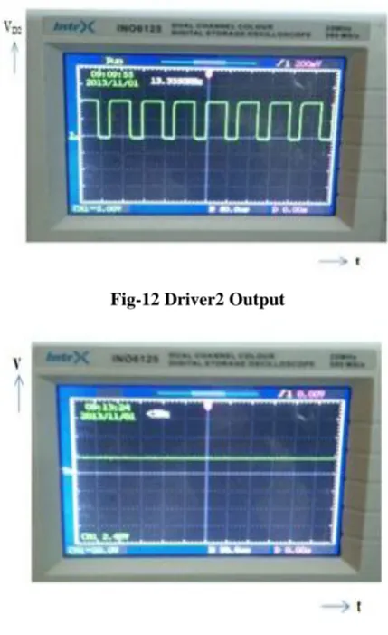
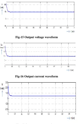
The hardware of the ILFC system is shown in Fig 7. It consists of a control circuit and a power circuit. Fig 8 shows the input voltage (DC). Fig 9 & 10 shows switching pulse1 and output of driver1 respectively. Fig 11 & 12 shows switching pulse2 and output of driver2 respectively. Fig 13 shows output voltage (DC) waveform.
Fig-8 Input Voltage(DC)
[image:3.595.62.328.55.778.2]Fig-9 M1 switching pulse
Fig-10 Driver1 Output
Fig-11 M2 Switching pulse
Fig-12 Driver2 Output
Fig-13 Output Voltage
V. SIMULATION OF THREE SWITCH FORWARD
CONVERTER
Fig 6.1shows the model Simulink for three switch converter. Output voltage waveform output current waveform and output power waveform are measured using scopes. Fig 6.1 Three switches forward converter using a resistive load
[image:3.595.59.275.58.399.2]Input voltage (300Volts) is represented in Fig 14. The output voltage is shown in Fig 15.
Fig-14 Input voltage waveform
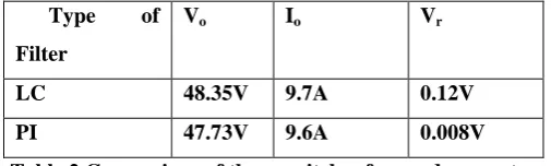
[image:3.595.58.279.415.769.2] [image:3.595.307.546.555.661.2]Fig-15 Output voltage waveform
[image:4.595.131.539.40.842.2]Fig-16 Output current waveform
Fig-17 Output power waveform
VI. PROTOTYPE OF THREE SWITCH INTERLEAVED FORWARD CONVERTER The hardware of the three switch ILFC system is shown in Fig 18. It composed of a control circuit and prime circuit. Input voltage (DC) is shown in Fig 19. The waveform of switching pulse1 and driver1 are represented in Fig 20 & 21 respectively. The output voltage is shown in Fig 22.
[image:4.595.48.305.48.451.2]Fig 18 Hardware setup
Fig 19 Input Voltage
[image:4.595.316.541.62.614.2]Fig-20 M1 Switching pulse
Fig-21 Driver1 output
[image:4.595.48.292.570.749.2]VII. COMPARATIVE RESULTS
Type of Filter
Vo Io Vr
LC 48.35V 9.7A 0.12V
PI 47.73V 9.6A 0.008V
7.1 COMPARISON BETWEEN TWO SWITCH
FORWARD CONVERTER WITH LC AND PI FILTER
The output voltage, output voltage ripple and current of two-switch forward converter using LC and PI filter are listed in table 1.
While comparing the output current and voltage, the two-switch forward converter with an LC filter hasa better result than the PI filter. But ripple content of voltage is lesser in two-switch forward converter with PI filter compared to that of the LC filter.
Type of
filter Vo Io For Vr
LC 48.38V 9.6A 0.3V
[image:5.595.52.290.47.188.2]PI 47.74V 9.5A 0.03V
Table 1 Comparison of a two-switch forward converter with LC and PI filter
7.2 COMPARISON BETWEEN THREE SWITCH
FORWARD CONVERTERS WITH LC AND PI FILTER
[image:5.595.47.294.293.371.2]Output voltage, current and output voltage ripple of three switches forward converter using LC and PI filter is shown in table 2. While comparing the output voltage and current, the two-switch forward converter with an LC filter hasa better result than the PI filter. But ripple content of voltage is lesser in two-switch forward converter with PI filter compared to that of the LC filter.
Type of Filter
Vo Io Vr
LC 48.35V 9.7A 0.12V
PI 47.73V 9.6A 0.008V
Table 2 Comparison of three switches forward converter with LC and PI filter
VIII. CONCLUSION
Two and three switch serial- input forward -converters with resistive load is simulated using MATLAB Simulink. The results of two switch forward converter using LC and PI filter are compared. The output of the LC filter is greater than that of the PI filter system. The output of three switches forward- converter system has better performance when compared to the two-switch forward converter system. Hardware is fabricated for both forward converters with resistive load and tested. Experimental results on prototype confirm the theoretical performance of the suggested converter.
REFERENCES
1. Tapan Vanker &- Gangavarapu Gurkumar,” Comparative-Analysis of PI& Fuzzy-Control for a Dual-Input DC/DC-Converter in Hybrid-Energy-Application,” 2017 IEEE-SPICES.
2. Alexander Cheng, and Smedley, “Analysis and Design of Forward Converter with Energy Regenerative Snubber,” IEEE Transactions on Power Electronics, Volume 25, No. 3, Mar 2010.
3. Z. Wang et al, “Reducing common mode noise in two-switch forward -converters,” Power Electronics., volume 26, no. 5, pp. 1522–1533, May 2011
4. K.M. Smedley et al, “Design of High Efficiency Fly back Converter with Energy Regenerative Snubber,” in Proc. Appl. Power Electron.Conf. Expo. (APEC 2008), 24–28 Feb., pp. 796–800. 5. K. Lin et al, “An Efficient L-C Snubber for Forward- Converters,”
Power Electronics., volume no. 6, pp. 1522–1531, Jun. 2009. 6. Moon et al, “Zero-voltage switching post regulation scheme for multi
output forward converter with synchronous switches,” IEEE Trans. vol. 58, no. 6, pp. 2378– 2386, Jun. 2011.
7. Y. Wei et al, “Wide Range Dual Switch Forward-Flyback Converter with Symmetrical RCD Clamp,” IEEE Transaction. Power Electron, 2005.
8. M. R. Reinert et al, “Transformer less Double-Conversion UPS Using a Regenerative Snubber Circuit,” IEEE Trans. Power Electron, 2009. 9. Z. Sajam et al, “Spike Suppression Method of Bidirectional High
Frequency Inverter using a Regenerative Snubber,” IEEE Trans. Power Electron, 2004.
10. M. Jinno et al, “Efficiency Improvement for S-R Forward Converters with L-C Snubber,” IEEE Trans. Power Electron., vol. 16, no. 6, pp. 812–820, Nov. 2001.
[image:5.595.43.296.518.594.2]