International Journal of Innovative Technology and Exploring Engineering (IJITEE) ISSN: 2278-3075, Volume-9 Issue-2, December 2019
Abstract: A sensor less BLDC (Brushless Direct Current) motor speed control is performed using PSO algorithm. The PSO algorithm manages the gain value of the PID controller. The speed of the BLDC motor is provided as the feedback to the controller. The error value is calculated by predetermined speed for the BLDC motor. Wind power generator is used as the input power source for driving BLDC motor. The output power of the wind power generator varies based on the wind speed. The variable input source for the BLDC motor affects the performance of the motor. In order to regulate the input voltage of the BLDC motor, SEPIC DC-DC converter is used. The PSO-PID controller controls the Gate pulse of the SEPIC converter. The model is developed in MATLAB/Simulink, the performance of the proposed PSO-PID control is measured in variable input power condition. The hardware model is developed using MSP430 microcontroller to test the efficiency of the PSO-PID controller in the real time environment.
Keywords : BLDC motor, PSO-PID, SEPIC converter, Wind power Generator, speed control..
I. INTRODUCTION
Brushless DC motors (BLDC Motors) are widely used in industrial applications were higher reliability and accurate control is needed. BLDC motor posses a simple structure with maximum speed range. Traditional AC motors are used in the industrial applications, which were replaced by the brushed DC motors. Development in the field of motor technology the BLDC motors are introduced with higher efficiency in handling speed and torque characteristics. In BLDC motors Brush based commutation is replaced with electronic commutation. The torque delivered by the BLDC motor is higher than its size. Thus, the BLDC motors are used in the applications were weight and space plays a critical factor.
The applications of BLDC motor was classified as follows open loop Applications, Closed loop Applications, positioning Applications. The examples like blowers, fans and pumps are classified under open loop applications. An elementary low cost controller is enough to control the BLCD motor for the open loop application. The closed loop application requires higher accuracy in speed control and better dynamic response. The house hold application like dryers, washers are the examples of closed loop applications.
Revised Manuscript Received on December 05, 2019.
Murali Dasari, Department of E.E.E, JNTUA Ananthapuramu, Ananthapuramu, India. Email: [email protected]
A Srinivasula Reddy, Department of Electrical Engg, CMR Engineering College, Hyderabad, Telangana. , India. Email: [email protected].
M.Vijaya Kumar, Department of Electrical Engg, JNTU College of Engineering, Ananthpur, India. Email: [email protected]
Even speed control is used in automotive applications like electronic steering, fuel pump control and engine control. These applications need advanced control algorithms. The positioning applications focus on faster response in speed and torque of the motor. Automation and Industrial applications, which use BLDC motors, are grouped in this category. These applications may change the direction of the rotation of BLDC motor more frequently. These applications posses four important phases they are Acceleration phase, Constant speed phase, Deceleration phase, Positioning phase. A complex algorithm is needed to control the BLDC motor connected to the load in all these phases. The control algorithm posses three control loops namely, Position control loop, Torque control loop and Speed control loop. A closed loop controller is required to perform these loop operations. The commutation time of the BLDC motor is reduced by adding a sensor along with the control system.
A. BLDC motors vs Traditional DC motors
The rotor in the electric motor is referred as commutator. In traditional DC motor brushes are placed to provide contact between DC electrical source and armature coil windings. Brushes provide mechanical contact to the several sections of commutator. The brush system and rotating commutator operates like a switches, which drives the armature coil in the sequence along the permanent magnet or an electromagnet. In BLDC motor the armature coil remains static. Instead of it permanent magnets rotate along the axis. Thus the problem of transferring the power to the armature axis is solved in BLDC motor. The commutator in the traditional DC motor was replaced with the electronic controller in the BLDC motor. The controller is programmed to control switching patterns of the armature coil. Advantages of the BLDC motors are Lesser operational noise, Longer life time, Higher speed ranges, Higher efficiency
B. Controlling BLDC motor
A Hall effect sensor is used to identify the position of the rotor to measure the speed of the BLDC motor. The main disadvantage of the BLDC motor is its manufacturing cost. Addition of Hall effect sensors increases the manufacturing cost. Some applications like submersible pumps, the BLDC motors are driven sensor less. Various algorithms as Field oriented control, direct back EMF zero crossing and indirect back EMF integration methods are introduced.
Adaptive Speed Control Algorithm for BLDC
Motor with Variable Input Source using PSO
Algorithm
To apply the BLDC motor in constant speed variable load application, a sensor less method with complex algorithm is required.
II. LITERATURESURVEY
A finite element analysis is used to measure mechanical flexibility and speed control of the BLDC motor. The magnetic field generated by the BLDC motor due to the switching action of PWM inverter is analyzed using non-linear time stepping finite element method. Maxwell stress sensor is used to measure torque and magnetic field generated by BLDC motor. The finite element method utilises the flexibility of rotor, shaft and bearing to measure the rotational motion of the rotor. The speed of the motor is controlled through PWM. A closed loop system is designed by providing magnetic and mechanical outputs as a feedback for control system and PWM pulse is generated based on the error value [1].To overcome the cost limitations in development of BLDC motors, a sensor less speed control systems were developed. The sensor less control systems utilises back EMF voltage signal to measure the speed of the BLDC motor. The back EMF value is nearly zero at lower speed. Flux estimation method generates higher error rate at lower speed ranges. Thus, these methods fail to measure speed of the BLDC motor at lower speed. In order to overcome this limitation speed independent function is derived from the deep knowledge based on physical properties of the BDC motor [2]. The Application specific integrated circuit (ASIC) is used to perform sensor less control over permanent magnet BLDC motor. The ASIC computes the commutation sequence of BLDC motor by combining the back EMF data from terminal voltages and phase locked loop. The input voltage can be distorted even by the switching of freewheel diode in motor control system. This affects the performance of the motor control system, to overcome this limitation a third harmonic back EMF is integrated with the ASIC system, which largely reduces the commutation retardation. This improves the performance of the BLDC motor with sensor less motor drive [3].Current mode control and Condition angle control are introduced to design a controller unit for BLDC motor speed control. Two states of operation is defined for BLDC motor thus the average speed is framed between these two operating points. Newton’s second law is used to frame equations for designing motor speed controller [4]. To reduce the size of the BLDC motor drive, a phase locked loop (PLL) and internal model (IM) speed control systems were integrated. Additional with it, PWM control and current sensing scheme are integrated in the motor drive which simplifies the hardware development of the BLDC motor speed control drive system. These integrations provides more accuracy and robustness in the control of BLDC motor. The hardware model developed using these integrated model produces compact structure and improves the current regulation performance in BLDC motor drives [5].
Vector based control is used to perform speed control in Permanent magnet synchronous motors. The outer spped loop in the vector based method reduces the performance of the vector based control system. in order to overcome this limitations the PI and fuzzy based control unit is used to
International Journal of Innovative Technology and Exploring Engineering (IJITEE) ISSN: 2278-3075, Volume-9 Issue-2, December 2019
To achieve high performance in BLDC motor speed control DS1103 controller is used. The DS1103 controller is interface with matlab simulink blocks to develop control software [12]. Inevitable voltage pulses were generated during the commutation period due to the higher speed range or driving heavier load by BLDC motor affects the accuracy of detecting the position of the rotor. This affects the performance of the sensor less BLDC speed control system. To overcome this fault higher precision sensor less BLDC drive is used. It uses active compensation method which uses phase locked loop based on the combination of 3rd harmonic back EMF, synchronic frequency filter and second order generalised integrator. The method was used to measure the precise occurred during the commutation points in the sensor less motor drive [13]. A model predictive controller is designed to control the four quadrant operation BLDC motor. It controls all the four quadrants without loss in power. The model is used to analyse the characteristics like torque, speed, back EMF of the four quadrant BLDC motor. Model predictive controller conserves the power at regeneration cycle [14]. The BLDC motor speed controller based on Back-EMF sensor less technique generates drawback at the initial state of the motor drive. At initial stage, the motor is in stand still position thus no back-EMF is generated. This technique uses V/F or I/F measurement method, which are more sensitive with input parameters. To overcome the problem the relationship between the energizing interval, preposition current, transient speed at the initial state of the BLDC motor is analysed. Through this analysis, the drive can be switched to self-synchronisation stage without adding any external synchronisation methods. To detect the speed at lower speed ranges, a line voltage difference zero crossing point detection circuit is developed. A neuro fuzzy controller is used based on phase error correction to measure the accurate commutation points at the higher speed ranges of BLDC motor [15].
III. METHODOLOGY
A constant speed BLDC motor control is designed using PSO based PID controller. The BLDC motor is powered by variable speed wind turbine. The variable output voltage of the wind turbine is controlled by feeding the output voltage to PWM rectifier and SEPIC DC – DC Converter. The SEPIC DC- DC converter is controlled using PSO based PID controller. The speed of the BLDC motor is assigned as a feedback to the PSO algorithm. The algorithm computes gain values of PID controller and triggers the SEPIC converter to maintain input voltage of the BLDC motor to run in the constant speed. Fig.1 shows the block diagram of the system.
Fig. 1 Block Diagram for Constant speed BLDC motor control.
A. SEPIC DC-DC Converter:
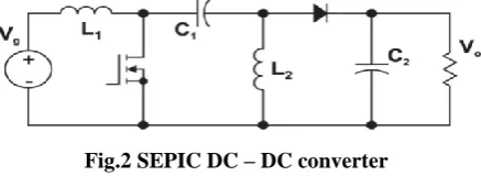
[image:3.595.319.538.138.218.2]SEPIC converter is specifically used for irregular input voltage source. SEPIC converter acts both as buck and boost converter. Fig. 2 shows the circuit diagram of SEPIC converter
Fig.2 SEPIC DC – DC converter
[image:3.595.310.543.420.532.2]The SEPIC converter posses two inductors which makes it idle from other converters. The converter was operated by rapidly switching the MOSFET on and off in specific frequency. When the input pulse is high, MOSFET is switched on then the L1 inductor was charged by the input voltage and the capacitor C1 voltage charges L2inductor. This situation is shown in Fig. 3. The diode was switched off and the capacitor C2 voltage drives the load.When the input pulse is set low, MOSFET is switched off thus the inductor voltages flow directly through the load. The capacitors are now in charging mode. By repeating the pulse, the load will be drive through capacitors and inductors cyclically. Based on the applied frequency the range of the output voltage is controlled. If frequency is low the inductors will charge for long period which results in increase in output voltage and vice versa.
Fig. 3 SEPIC Functions in Switch ON & OFF mode The pulse generated to control the MOSFET is generated using PID controller. The speed of the BLDC motor is applied as a feedback to the PID controller. The Gain of the PID controller is tuned using PSO algorithm.
B. PID Controller
[image:3.595.54.286.644.739.2]C(s)
P(s)
[image:4.595.52.274.55.197.2]I(t)
E(t)
O(t)
Fig. 4 General Feedback System
The control transfer function of PID controller is defined as
(1)
The parameters of proportional, integral and derivative control is represented as . These gain variables are
used to tune the output of the controller. The BLDC motor is used as the operating function P(S). the speed of BLDC motor is provided as a feedback to the control system. PSO algorithm is used to improve the tuning of the PID system. The gain values for P, I and D are assigned by PSO algorithm.
C. PSO Algorithm
PSO algorithm was developed based on the swarm intelligence from characteristics of birds and fishes. The systems involved in the optimisation algorithm were represented as particles. The particles updates the velocity and positions based on the values gathered from the other particles. Each particle posses three characteristics, fitness, position and velocity. The fitness represents the optimal function, position represents the distance of flight and velocity specifies the direction of flow. Every particles record the present optimal solution in space. Moreover, the process was performed in iteration fashion. Once the better solution is identified then the solution will be taken as base for the next iterative solution. The optimization algorithm initializes with the collection of particles and iterations were generated to identify the optimal solution. The optimal solution was refined at every iteration. is the optimal solution generated by the individual particle and is the optimal solution generated by complete particles in the system at current time. The system terminates when the iterations generate same optimal solution. The maximum iteration count is represented as N. PSO algorithm determines the position of m particles as I at the kth iteration as and the velocity is determined as . The velocity and the position of individual particles at each iteration is generated using
(2)
Were represents weight factor of inertia, c1 and c2 are acceleration constant, r1 and r2 are random variables within 0 and 1. represents best previous position of kth particle and refers the best particles from the collection of particles in the system. To refine the convergence velocity, the weight factor of inertia is replaced with the shrinkage factor. The equation to determine the location of the particle remains same. The equation to determine velocity is updated as
were k is defined as , were and
(3)
The local searching capability of the PSO algorithm is improved using shrinkage factor. The velocity of the particles can be controlled within the bounded range. The PSO algorithm with the shrinkage factor is applied over the PID controller to assign the gain values of . The values
are tuned to obtain maximum controlled result. Initialising with P, I, D particles, the system is framed in three-dimensional space. The fitness value is generated for each particle and the best solution is determined in iteration process. Once the best solution is obtained the value is assigned as extreme value of that particular particle. Then several best solutions were obtained in the iterative process. The best position of the particle is framed from the optimal value of the iteration experience. The velocity of the particle is generated within the bounded range. The objective function is developed by integrating the absolute error and performance index with time interval.
(4)
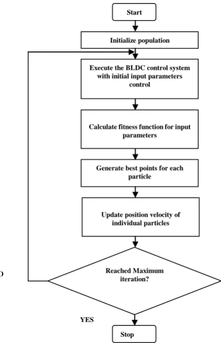
[image:4.595.319.539.388.729.2]were e(t) is systematic error, u(t) is the controllers output and are the weights of the particle. The steps in the process of PSO based PID control is shown in Fig.5 flowchart.
Fig.5 Flow chart of PSO-PID controller. Start
Initialize population
Execute the BLDC control system with initial input parameters
control
Calculate fitness function for input parameters
Generate best points for each particle
Update position velocity of individual particles
Reached Maximum iteration?
Stop NO
International Journal of Innovative Technology and Exploring Engineering (IJITEE) ISSN: 2278-3075, Volume-9 Issue-2, December 2019
IV. RESULTSANDDISCUSSIONS
[image:5.595.311.544.49.479.2]BLDC motor speed control using PSO-PID controller is simulated using MATLAB/Simulink. The speed of the BLDC motor is provided as a feedback to the PSO-PID controller. The speed and torque of BLDC motor is measured using sensorless back EMF technique. BLDC motor is powered using variable speed wind generator. The output voltage generated by wind generator is variable. The varaible input voltage to the BLDC drive affects the performance of the BLDC motor. To overcome this limitations SEPIC DC-DC converter is connected between the wind generator and BLDC motor drive. The MOSFET in the SEPIC converter is driven through PSO-PID controller. The frequency of the gate pulse varies based on the speed of the BLDC motor. P, I, and D gain values of PID controller is tuned by PSO algorithm which stabilise the BLDC motor speed in fixed RPM even applying variable input source.
[image:5.595.48.289.261.409.2]Fig. 6 wind power generator voltage output The output of the wind power generator varies based on the wind speed. Fig.6 shows the output voltage generated by the wind power generator by providing variable input wind speed. The peaks of the output voltage vary frequently based on the speed of the rotor in wind turbine. Fig.7 shows the current generated from the wind turbine. Maximum of 250 volts and 145mA current was generated from the wind power generator model.
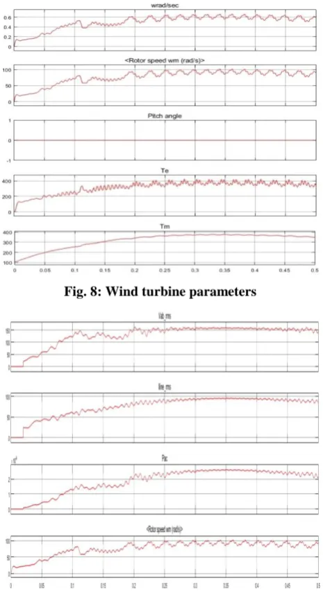
Fig. 7: Wind power generator current output The pitch angle, mechanical torque, and rotor speed was shown in Fig. 8. The mechanical torque generated by the wind turbine depends on the nominal power generated and speed. The pitch angle is made constant. The rotor speed varies based on the input wind speed variable. The generator speed was refered with the unit wrad/sec. The speed of the generator depends directly over the speed of the rotor in wind turbine.
Fig. 8: Wind turbine parameters
Fig. 9 RMS voltage and current, output power and wind turbine rotor speed.
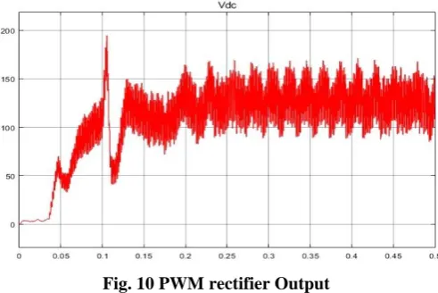
[image:5.595.48.289.519.654.2]Fig. 10 PWM rectifier Output
[image:6.595.306.541.245.389.2]The DC output of the PWM rectifier depends on the AC input provided by the wind power generator. Vienna rectifier is used instead of diode rectifier to reduce the voltage drop generated by the diodes in the rectifier circuit and Vienna rectifier also reduces the ripples compared to the diode rectifier.The generated DC voltage is then feed to the SEPIC DC-DC converter, were the inductor and capacitors filters the input DC voltage. SEPIC converter controls the amount of output voltage based on the triggering pulse applied to the gates of the MOSFET placed in SEPIC converter. Fig. 11 shows the output controlled DC voltage of SEPIC converter. The output voltage was rated about 145v to maintane1500 rpm speed in BLDC motor.
Fig. 11 SEPIC output voltage
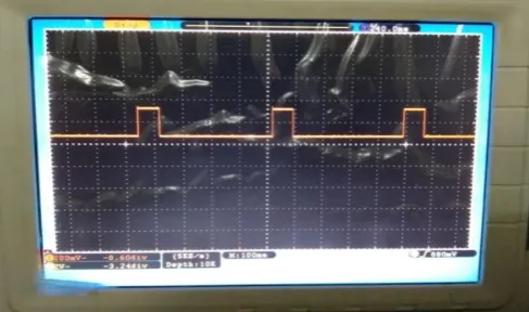
[image:6.595.48.294.378.501.2]The output voltage of SEPIC convereris boosted or bucked based on the trigger signal generated by the PSO-PID controller. The error in speed of the BLDC motor is measured with the reference speed. The error value is processed by the PSO algorithm and the gain values P, I, D values are fixed to the PID controller in order to generate a trigger pulse to maintain lesser error value generated in the BLDC motor. Fig.12 shows the PWM pulse generated by the PSO-PID controller. The frequency and duty cycle rate of the PWM pulse is controlled based on the negative or positive error condition occurred at the BLDC motor feedback.
Fig. 12 SEPIC PWM input
When the speed of the BLDC motor is lower than the reference speed it is refered as positive error and the speed is higher than the reference speed then it is negative error. The frequency of the pulse increases during the positive error thus the output voltage of SEPIC converter increases and the frequency of the pulse decreases for negative error thus the output voltage of the SEPIC converter reduces. By balancing the output voltage the speed of the BLDC motor is maintained at constant speed. The regulated DC voltage Output of SEPIC converter is feed to the three phase inverter. The inverter converts the input DC voltage into AC voltage and feed to the BLDC motor. The inverter is used to drive the BLDC motor. Fig. 13 shows the single phase output of the inverter. The output AC voltage was measured 145v AC, thus the voltage generated by SEPIC converter is directly converted into AC voltage by the inverter circuit to drive the BLDC motor.
Fig. 13 Inverter Output
[image:6.595.306.543.459.628.2]The AC voltage generated by the inverter is feed to the BLDC motor. The Fig. 14 shows the rotor speed of the BLDC motor. The speed of the motor is fixed constant at 1500 rpm. The system reached steady state at 0.15 seconds. The speed of the rotor is feed backed to the control unit.
Fig. 14 BLDC motor speed
[image:6.595.47.293.642.768.2]International Journal of Innovative Technology and Exploring Engineering (IJITEE) ISSN: 2278-3075, Volume-9 Issue-2, December 2019
Figure. 15 BLDC motor stator current
Fig. 16 Torque of BLDC motor
[image:7.595.305.547.50.193.2]The speed of the BLDC motor is calculated based on back-EMF zero crossing method. It is the simplest and reliable technique to measure the position and speed of the motor in sensor less approach. The simulation results proved the stability of the system using PSO-PID controller. The efficiency of the controller is tested in hardware environment using MSP430FR5529 launch pad. The real time environment generate additional challenges in maintaining speed and position of BLDC motor due to addition of harmonics and errors generated in the system. The SEPIC converter is designed using 680 inductor and 1000 capacitance. IRF540 power MOSFET is used to switch the SEPIC converter. Trigger pulse for SEPIC converter is generated using PSO-PID control design in MSP430 controller. Fig. 17 shows the hardware implementation of the PSO-PID based BLDC motor speed control.
Fig. 17 Hardware Setup
Fig. 18 Vienna inverter output voltage
[image:7.595.305.548.265.378.2]A variable AC input source is provided to run the BLDC motor. In order to regulate the input voltage source the AC voltage is rectified using vienna rectifier. Fig. 18 shows the output DC voltage of the Vienna rectifier.
Fig. 19 SEPIC output voltage
[image:7.595.306.550.478.622.2]The rectified DC voltage is provided to the SEPIC converter. The input voltage is variable based on the applied input variable AC source. Thus the SEPIC operate in both buck and boost converter logic to maintain the constant DC output. Fig. 19 shows the regulated DC output generated by the SEPIC controller.
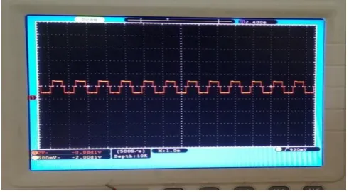
[image:7.595.49.289.512.714.2]Fig. 21 3 stage Inverter triggering pulse
The controlled DC voltage is then passed to the Inverter were the regulated DC voltage is converted to the AC voltage which used to drive the BLDC motor. Fig. 21 shows the PWM pulses generated by the PIC microcontroller to control the inverter function. Fig. 22 shows the output of the 3-stage inverter. This AC voltage source is then feed to the BLDC motor.
Fig.22 3stage inverter output
V. CONCLUSION
PSO based PID controller is introduced to control the speed of the BLDC motor. The BLDC motor with variable input source was controlled using PSO-PID controller and the SEPIC converter. The SEPIC converter regulates the input voltage of the BLDC motor, the PSO-PID controller controls the gate pulse of the SEPIC converter. Based on the generated gate pulse, SEPIC converter acts as boost or buck converter. Thus, the output voltage of the converter is regulated which proportionally maintains the speed of the BLDC motor. The performance of the BLDC motor drive with PSO-PID is tested by simulating using MATLAB/ Simulink . And the model is developed in a hardware environment to test the performance of the PSO-PID controller in the real time environment. The PSO-PID control algorithm is executed using MSP430 microcontroller and the output of the hardware model is compared with the simulated results and proved to be effective in real time environment.
REFERENCES
1. G. H. Jang, J. H. Chang, D. P. Hong, and K. S. Kim, “Finite-element analysis of an electromechanical field of a BLDC motor considering speed control and mechanical flexibility,” IEEE Trans. Magn., vol. 38, no. 2, pp. 945–948, 2002.
2. T. H. Kim and M. Ehsani, “Sensorless control of the BLDC motors from near-zero to high speeds,” IEEE Trans. Power Electron., vol. 19, no. 6,
3. I. S. Shen J X, “Sensorless Control of Ultrahigh-Speed PM Brushless Motor Using PLL and Third Harmonic Back EMF,” IEEE Trans. Ind. Electron., vol. 53, no. 2, pp. 421–428, 2006.
4. Fernando Rodriguez, “A Novel Digital Control Technique for Brushless DCMotor Drives,” IEEE Trans. Ind. Electron., vol. 54, no. 5, pp. 2365–2373, 2007.
5. C. T. Pan and E. Fang, “A phase-locked-loop-assisted internal model adjustable-speed controller for BLDC motors,” IEEE Trans. Ind. Electron., vol. 55, no. 9, pp. 3415–3425, 2008.
6. A. V. Sant, “PM synchronous motor speed control using hybrid fuzzy-PI with novel switching functions,” IEEE Trans. Magn., vol. 45, no. 10, pp. 4672–4675, 2009.
7. C. Xia, Z. Li, and T. Shi, “A control strategy for four-switch three-phase brushless DC motor using single current sensor,” IEEE Trans. Ind. Electron., vol. 56, no. 6, pp. 2058–2066, 2009.
8. V. Bist, “An Adjustable Speed PFC Bridgeless Buck-Boost Converter Fed BLDC Motor Drive,” IEEE Trans. Ind. Electron., vol. 61, no. 6, pp. 2665–2677, 2015.
9. C. Cui, G. Liu, and K. Wang, “A novel drive method for high-speed brushless dc motor operating in a wide range,” IEEE Trans. Power Electron., vol. 30, no. 9, pp. 4998–5008, 2015.
10. L. I. Iepure, I. Boldea, and F. Blaabjerg, “Hybrid I-f starting and observer-based sensorless control of single-phase BLDC-PM motor drives,” IEEE Trans. Ind. Electron., vol. 59, no. 9, pp. 3436–3444, 2012. 11. S. Chen, G. Liu, and L. Zhu, “Sensorless Control Strategy of a 315 kW High-Speed BLDC Motor Based on a Speed-Independent Flux Linkage Function,” IEEE Trans. Ind. Electron., vol. 64, no. 11, pp. 8607–8617, 2017.
12. D. Potnuru, A. M. K., and S. Ch., “Design and implementation methodology for rapid control prototyping of closed loop speed control for BLDC motor,” J. Electr. Syst. Inf. Technol., vol. 1, no. 1, pp. 1–13, 2017.
13. X. Song, B. Han, S. Zheng, and J. Fang, “High-Precision Sensorless Drive for High-Speed BLDC Motors Based on the Virtual Third Harmonic Back-EMF,” IEEE Trans. Power Electron., vol. 33, no. 2, pp. 1528–1540, 2018.
14. J. Gopinath.M, Yuvaraja.T, “Implementation of Four Quadrant Operation of BLDC Motor Using Model Predictive Controller,” Elsevier, vol. 14, no. 1, pp. 1665–1672, 2017.
15. X.Zhou, X. Chen, C. Peng, and Y. Zhou, “High Performance Non-Salient Sensorless BLDC Motor Control Strategy from Standstill to High Speed,” IEEE Trans. Ind. Informatics, vol. 3203, no. 3, pp. 1–11, 2018.
AUTHORS PROFILE
Mr.Murali Dasarireceived the B.Tech . Degree in EEE from MITS ENGG College, Madanapalle, Chittor(Dt), Andhra Pradesh, India, from JNTU University and M.Tech in Power Electronics from VNRVJIET, Bachupalli ,Hyderabad , Andhra Pradesh, India, from JNTU University. He has teaching experience of 09 years & currently working as Assistant Professor in geethanjali Institute of Science & Technology, Gangavarm, Nellore Dist, Andhra Pradesh, India in the Dept. of Electrical & Electronics Engg he is working in the area of powerelectronics & drives.
Dr. A. Srinivasula Reddy, presently working as a Principal in CMR Engineering College, Hyderabad, A.P., India. He completed his AMIE degree in 1999 and ME Degree with specialization in Power Systems in 2001 & Ph. D in 2010 from J.N.T.U.A, Anantapur, Andhra Pradesh, India. He has nearly 18 years of teaching experience and his areas of interest Power Systems and Field Computations, Power Electronics Drives and AI Applications in Power Engineering. He published about 17 papers in international Journals and about 22 papers in National and International Conference proceedings. He also published two national and one international Books. He is guiding 8 Ph.D. Scholars. He has been there as Reviewer for JESIT, and EPSR of Elsevier and other couple of journals. He is the evaluator for
[image:8.595.46.292.310.445.2]International Journal of Innovative Technology and Exploring Engineering (IJITEE) ISSN: 2278-3075, Volume-9 Issue-2, December 2019
University, and MGR University, Chennai, India.
Prof. M.Vijaya Kumar has obtained his B.Tech from S.V.University and M.Tech from NIT, Warangal and PhD from JNTU, Hyderabad. He has 24 years of teaching experience. He has published 65research papers at national and International level. His research area is power quality improvement in power systems.