NUMERICAL STUDY OF FLUID FLOW AND HEAT TRANSFER IN MIXING ELBOW
MOHD IDHAM KHALID BIN ABU HASAN
This Report Is Submitted In Partial Fulfillment Of Requirements For The Bachelor Degree of Mechanical Engineering (Thermal-Fluid)
Faculty of Mechanical Engineering University Technical Malaysia Melaka
SUPERVISOR DECLARATION
"I hereby declare that I have read this thesis and in my opinion this report is sufficient in terms of scope and quantity for the award of the degree of
Bachelor of Mechanical Engineering (Thermal-Fluids)"
Signature:
... k'
... .
Supervisor:... N.
~.~
..
~!~.iv~
.. ~r.
..
~~wr
11rt
DECLARATION
"I hereby declare that the work in this report is my own except the summaries and quotations which have been duty acknowledge."
Signature:
Author:
Date:
···~···
..
~
...
~~~
...
~./P.
..
~:
..
~.Y
...
~~
~4#1 ~ %/3 .
... u: .. , ...
.
Dedicated to my beloved Mother, Father and Brothers ...
iv
ACKNOWLEDGEMENT
All praise to Allah Most Gracious, Most Merciful, Who, Alone, brings
forgiveness and light and new life to those who call upon Him.
First of all, thanks to Allah s.w.t for all His guidance and blessing through all
the hardship encountered whilst completing this thesis. In preparing this thesis, I was
in contact with many people, researchers, academicians and practitioners where they
have contributed towards my understanding and thoughts. In particular, I wish to
acknowledge with much appreciation the crucial role of my supervisor, Miss Nur
Hazwani Mokhtar for guidance, encouragement, critics and friendship.
I would like to express my deepest appreciation to my family especially my
beloved mother, Mimunah Muhamad and all of my siblings for all of their loves and
supports. I am also indebted to FKM lecturers for their guidance to complete this
thesis, especially to my final year project panels
Mr.
Mohd Hafidzal Bin MohdHanafi and
Mr.
MD Isa Bin Ali. Without ther continued support and interest, thisthesis would not have been presented here.
Lastly I would like to recognized my fellow undergraduate colleagues for
v
ABSTRACT
Study of heat transfer and fluid flow in piping system often involves of
temperature, heat flow, velocity and dynamic viscosity from the entrance the fluid
enter until the fluid flow out of the pipe outlet. This study focus on the behaviour of
heat transfer and fluid flow in mixing elbow. Mixing elbow is a region where two
types of fluid flow with different temperature and high Reynolds number is
intensively mixed together and is among typical geometries exactly where
temperature fluctuation happens. Temperature fluctuation in liquid causes high cycle
thermal fatigue within structure materials based on temperature distributions as well
as time variations. The main objective of this study is to simulate and analyze the
flow and temperature field in the mixing elbow by simulate with several models of
different inlet diameters. The simulation process is done by using Computational
Fluid Dynamic (CFO) software. From the simulation, it is proven that the mixed flow
appeared as turbulent and caused the temperature changes which eventually generate
a cyclic stress that contributes to thermal fatigue failure on the welded joint and Flow
accelerated corrosion (F AC) also founds to be the contributor for thermal fatigue
failure at the elbow. Besides that, it is found that from the simulation test of three
models with different diameters, it would longer the service life of mixing elbow and
vi
ABSTRAK
Kajian tentang pemindahan haba dan aliran bendalir dalam sistem perpaipan
sering melibatkan suhu, aliran haba halaju, dan kelikatan dinamik dari awal
kemasukan bendalir sehingga aliran bendalir keluar dari salur keluar paip. Kajian ini
memberi tumpuan kepada tingkah laku pemindahan haba dan aliran bendalir dalam
siku pencampuran. Siku pencampurkan merupakan tempat di mana dua jenis aliran
cecair dengan suhu yang berbeza dan dengan nombor Reynolds yang tiggi
dicampurkan bersama secara intensif dan adalah antara geometri yang kebiasaannya
menjadi tempat di mana turun naik suhu berlaku. Turun naik suhu dalam cecair
menyebabkan kitaran keletihan haba yang tinggi dalam struktur bahan berdasarkan
taburan suhu serta variasi masa. Objektif utama kajian ini adalah untuk
mensimulasikan dan menganalisis aliran dan medan suhu dalam siku pencampuran
dengan menjalankan simulasi terhadap beberapa model yang mempunyai saluran
diameter masuk yang berbeza. Proses simulasi dilakukan dengan menggunakan
perisian Dinamik Bendalir Komputeran (CFD). Daripada simulasi yang telah
dijalankan, ianya terbukti bahawa aliran bercampur menghasillkan arus bergelora
dan menyebabkan perubahan suhu yang akhimya menjana tekanan kitaran yang
menyumbang kepada kegagalan lesu haba pada sendi kimpalan dan Aliran Pecutan
Hakisan (F AC) juga terbukti menjadi penyumbang untuk kegagalan lesu haba di
sesiku. Selain daripada itu, didapati bahawa daripada ujian simulasi tiga model
dengan diameter yang berbeza, hayat perkhidmatan siku campuran akan jadi lebih
lama dan keselematan siku campuran boleh ditingkatkan dengan membesarkan saiz
vii
TABLE OF CONTENTS
CHAPTER TITLE PAGE
DECLARATION ii
DEDICATION iii
ACKNOWLEDGEMENT iv
ABSTRACT v
ABSTRAK vi
TABLE OF CONTENT vii
LIST OF TABLE ix
LIST OF FIGURE x
LIST OF SYMBOL XII
LIST OF APPENDIX xiii
CHAPTER I INTRODUCTION
1.0 Introduction 1
1.1 Importance of Study 3
1.2 Objectives 3
1.3 Research Scope 3
1.4 Problem Statement 4
CHAPTER2 LITERATURE REVIEW 5
2.0 Introduction 5
2.1 Correlation Matrix 8
2.2 Simulation Method 10
2.2.1 Experiment 10
2.2.2 Computational Fluid Dynamic (CFO) 11
2.3 Turbulence Modelling 12
viii
2.5 Model Validation
15
2.5.1 Material Properties
15
2.5.2 Boundary Condition
16
2.6 Data Validation
17
CHAPTER3 METHODOLOGY
19
3.0 Introduction
19
3.1 Flow Chart
20
3.2 Methodology Determination
20
3.2.1 3-D Mixing Elbow Reconstruction
23
3.2.2 Grid Dependency
25
3.2.3 Model Validation
28
3.2.4 Simulation of Various Inlet Diameters
29
CHAPTER4 RESULT & ANALYSIS
31
4.0 Introduction
31
4.1 Validation
32
4.2 Temperature Field Inside Mixing Elbow
34
4.3 Turbulent Behaviour Inside Mixing Elbow
36
4.4 Flow Accelerated Corrosion (F AC)
38
4.5 Effect of Diameter On Flow Inside Mixing Elbow
41
4.5.1 Turbulent Flow Comparison
42
4.5.2 Temperature Field Comparison 44
4.5.3 Pressure Comparison
46
CHAPTERS CONCLUSION
47
5.1 Conclusion
47
5.2 Recommendation
49
REFERENCES
50
BIBLIOGRAPHY
52
ix
LIST OF TABLE
TABLE TITLE PAGE
Table 2.1 List of journals 8
Table 3.1 Number of nodes and element for three type of mesh 25
Table 3.2 Properties of water 28
Table 3.3 Material properties for Aluminium 28
Table 3.4 Boundary condition of mixing elbow 29
Table 3.5 List of tested diameters for mixing elbow 30
Table 4.1 Validation data for k-E, Experiment, LES and k-ro 60
Table 4.2 Comparisons of three simulation models 39
x
LIST OF FIGURE
FIGURE TITLE PAGE
Figure 2.1 Mixing elbow principle 6
Figure 2.2 Location ofthennal fatigue 6
Figure 2.3 Cracked on Civaux Reactor mixing elbow 7
Figure 2.4 Schematic of test section 10
Figure 2.5 Quadrilateral/hexaheral meshes and triangle/tetrahedal meshes 14
Figure 2.6 Cross-section of the computational mesh used with a mesh size of 14
2mm (a) In the mixing pipe. (b) In the hot leg
Figure 2.7 Graph of peak to peak temperature difference of outer skin wall 17
surface
Figure 2.8 Temperature fluctuation profile 18
Figure 3.1 Turbulent model setup 22
Figure 3.2 Mixing elbow dimensions (inches) 23
Figure 3.3 Isometric view of mixing elbow 24
Figure 3.4 Mixing elbow grid 26
Figure 3.5 Isometric view of mixing elbow grid 27
Figure 4.1 Contours of static temperature of mixing elbow 32
Figure 4.2 Temperature contour of mixing elbow 35
Figure 4.3 Location ofthennal fatigue 36
Figure 4.4 Turbulent kinetic energy contour 37
Figure 4.5 Velocity vector inside the mixing elbow 38
Figure 4.6 Velocity vector at the mid plane elbow 40
Figure 4.7 Accelarated fluid flow 40
Figure 4.8 Flow separation and vortices 41
Figure 4.9 Comparison of turbulent contours 43
xi
Figure 5.1 3-D mixing elbow reconstruction 54
Figure 5.2 Geometry meshing process 55
Figure 5.3 Simulation setups 56
Figure 5.4 Simulation result 57
Figure 5.5 Converged computation for Small diameter 58
Figure 5.6 Converged computation for Medium diameter 59
p
u
D
µ
=
=
=
=
LIST OF SYMBOL
Density {kg/m3)
Velocity (mis)
Diameter of pipe (m)
Dynamic viscosity (kg/ms)
xiii
LIST OF APPENDIX
APPENDIX TITLE PAGE
Appendix A Simulation procedures 54
Appendix B Prove of converged computations 58
Appendix C Validation data for k-E, Experiment, LES and k-ro 60 Appendix D Temperature data for three different diameter sizes of mixing 61
elbow
1
CHAPTERl
INTRODUCTION
1.0 INTRODUCTION
In mixing elbow, heat transfer through convective fluid flow occurs due to
differences in density of the fluid at the surface. In addition, there is also a flow of
changes that cause the phenomenon of laminar and turbulent flow depends on the
flow of phase change. The mixing between two types of fluid with different
temperature will caused a temperature fluctuation which will generate a cyclic stress
and contributes to thermal fatigue failure (Aulery et al,2012). Besides that, the
changes in flow direction in the mixing elbow will produce a secondary or flow
separation due to biased velocity distribution . The parameter taken into
consideration are the pipe diameter or length of pipe required, velocity of fluid flow
and fluid flow rate.
In general, heat transfer process can be seen all around us. Basically the heat
transfer mechanism can flowing through three processes of conduction, radiation and
convection (Holman, J.P., 1986). In recent times, a lot of research in the field of heat
2
which the energy transfer occurs between systems that communicate with each other
due to differences in temperature. It is also a phenomenon that occurs at the
boundary of the system is a redistribution of internal energy in the system.
Convective heat transfer process is mainly a surface phenomenon. Surface
may be a surface in, such as the wall of the pipe or channel, or the outer surface of a
particular body (Holman, J.P., l 986).
In
the process of convection, mass andmomentum transfer and heat transfer occur simultaneously.
The design and analysis of engineering systems involving fluid flow is either
by experiment or calculation. Previous method involves building models and tested
in wind tunnels or other equipment. Latest methods involving differential equations,
or computing solutions.
CFO code is used to calculate the properties related to heat transfer and fluid
flow. Practical problems in engineering mostly involving fluid flow and heat transfer.
CFO is also used to shorten the design cycle by controlling the parameters relevant.
In addition, it can reduce the amount of equipment to make the experiment thus
reduced the cost of making the experiment.
CFO focuses on fluid flow equations using a computer software. Modem
engineers have now been applied to both the experimental and CFO analysis to
obtain the details of the velocity profile of the fluid flow, pressure and temperature.
Meanwhile, experimental data are often used for validation of the CFO solution with
computing systems adapt and experiment to find the overall quantity.
Therefore, the process of simulating and analyzing the fluid flow and heat
transfer for this study can be done by using the CFO software. The simulation can be
3
1.1 IMPORTANCE OF STUDY
This research focus on the heat transfer and fluid flow inside a mixing elbow,
starting from the flow entering the inlet until it flow out through the pipe outlet. The
importance of this study are as follow:
i. To equip students with the knowledge and skills related to disentangle the
various methods in heat transfer and fluid flow.
ii. To apply the application ofCFD simulation and knowledge up on the run.
iii. To be able to analyze the results of the simulation data and make
recommendations regarding the improvement of the research.
iv. To be able to implemented ANSYS FLUENT 14.0 software in a simulation
of the fluid flow and heat transfer.
1.2 OBJECTIVES
This research is focussing on the heat transfer and the fluid flow inside a
mixing elbow, starting from the flow entering the inlet until it flow out through the
pipe outlet. The objectives are as follow:
i. To simulate and analyze the flow and temperature field in the mixing elbow.
ii. To simulate with several models of different inlet diameters.
1.3 RESEARCH SCOPE
This research is focussing on the heat transfer and the fluid flow inside a
mixing elbow, starting from the flow entering the inlet until it flow out through the
4
i. Design a 3-dimensional (3-D) model of mixing elbow by using CFD application.
ii. Simulate the 30 mixing elbow model with various inlet diameter by using CFD
iii. Visualize and analyze the results of the fluid flow and heat transfer in mixing elbow
1.4
PROBLEM STATEMENT
Mixing elbow is a region where a cold and hot flow is intensively mixed together, where the flow appears as turbulent flow. Geometry of mixing elbow is consists of two inlets and one outlet. The main inlet is where the entrance of the hot flow and the branch inlet is where the cold flow entering the piping system. The mixed flow is then will flow out through the outlet of the mixing elbow. At the mixing region, a heat transfer process takes place which caused a temperature changes. In another words, once the two types of fluid mixed together, temperature fluctuation will happens. This temperature fluctuation will generate a cyclic stresses in the mixing region. The cyclic stresses will be transmitted to the adjoining structure, which is the weakest part of the mixing elbow with fairly low attenuation.
5
CHAPTER2
LITERATURE REVIEW
2.0
INTRODUCTION
Mixing elbow is a region where two types of fluid flow with different
temperature and high Reynolds number is intensively mixed together. Autery et al,
(2012) states that, heat transfer process takes place in the mixing elbow from high
temperature substances to lower temperature substances. Mixing elbow is among
typical geometries exactly where temperature fluctuation happens. The principle of
mixing elbow is as illustrated in Figure 2.1 below.
As seen from Figure 2.1, mixing elbow is consists of two inlet and one outlet.
The two inlets can be classified as main inlet and branch inlet. A hot properties fluid
will enter the main inlet and flow through the pipe. Meanwhile, a cold fluid will enter
the pipe through the branch inlet. Until it reached a certain point, the two types of
6
During the mixing of the two fluids, there will be a temperature changes which known as temperature fluctuation. Aulery et al, (2012) explained that, this temperature fluctuation will generate a cyclic stresses in the mixing region. The cyclic stresses that been generated will be transmitted to the adjoining structure,
which is the weakest part of the mixing elbow with fairly low attenuation. As seen from Figure 2.2 below, the cyclic stress is acted on the location of the weld, where later on it will initiate a crack on the adjoining structure. This cyclic stress is a potential cause of thermal fatigue failure (Autery et al, 2012).
Hot fluid
Mixture
t
[image:20.518.141.387.224.439.2]Cold fluid
Figure 2.1: Mixing elbow principle.
Mixing region
'")
·
-
.
··
n;
·1
x
o1
~
area
')
-
.
.
_
ho1
,/
') "(' J') \' ')
:..
-- - --- _- - -__ ~._... . . _ . . J _ _ _ .. - -. . .
.
.
~..
I
/
""
1
d
1
1
L
oc
a1i
on of
lhen
n
Ma1
i
1Ue
c
o
ld
[image:20.518.138.390.498.693.2]7
On the other hand, El-Gammal et al, (20 l 0) states in the finding that the
changes in flow direction due to the geometry of the mixing elbow will produce a
secondary flow or flow separation due to biased velocity distribution. This biased
velocity is a factor that responsible for Flow Accelerated Corrosion (F AC) at the
elbow. F AC is a slow degradable process where the flow will damaging or thinning
the protective layer of the piping component and soon will initiate a crack on the pipe
surface. Meanwhile, Crawford et al, (2007) also states that the secondary flow that is
produced by the biased velocity distribution will induce a pressure drop along the
elbow. This pressure drop will cause a significant increase in wall shear stress along
the mixing elbow.
There are several incidents involving mixing elbow, for examples thermal
fatigue cracked at Superphenix Reactor, France on April 1996, Almeria solar plant,
1996, sodium leaked, Monju Reactor, Japan, December 1995 (Aulery et al, 2012)
and thermal fatigue cracked at Civaux Reactor, France on May 1998 (Passuto et al,
2007). The Figure 2.3 below shown an example of thermal fatigue cracked which
happened at Civaux Reactor.
Initial thermal
[image:21.518.170.430.458.681.2]fatigue cracked
8
2.1 CORRELATION MATRIX
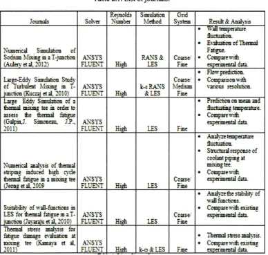
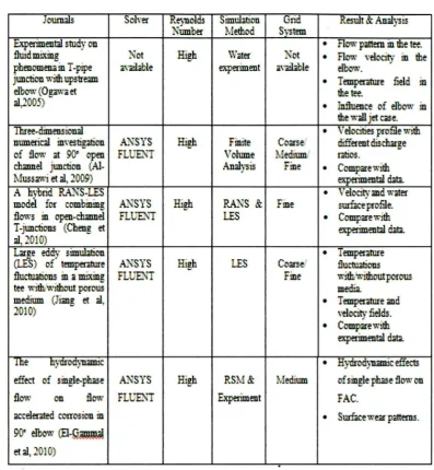
Table 2.1 below shows the lists journal that is found to be related to this
study. The journals have been extracted in terms of CFO solver, Reynolds number,
simulation method, grid system, and results and analysis. As seen from the matrix
below, most of previous researchers used ANSYS FLUENT as their solver which
ideal on solving internal flow with high Reynolds number. The common method that
have been used in their research is Large Eddy Simulation (LES). Meanwhile, the
results of their simulation were validated by compare with the experimental data or
[image:22.518.71.460.327.696.2]previous researcher's data.
Table 2.1: List of journals.
Reynolds Simullti n Grid
Jounuls Solver Number Method System Result & Aulysis
• \Vall temperature
flutnution.
•
E\·:W3tion of ThermalNumerical Simulation of Fatigue.
Sodium Mixing in a T-junction A1~SYS RA1~S& Co:arsef
•
C-omp:arewith(Aulerv et al, 2012) FLUENT Hi2.h LES Fine emerimental dm.
•
Flow prediction .Large-Eddy Simulation Study Com el
•
Comparison withof Turbulent l\futing in T- .6J-SYS k-£RA_NS Medium \nus resoluti n.
iunction (KuCZ3i et al, 2010) FLUENT Hi2.h &LES Fine
Large Eddy Simulation of a
•
Predicti non mez andthermal mixing tee in order to fluctulling temperature.
assess the thermal fatigue • Comp:arewith
(Gilpin). Simoneau, .P., .6J-SYS experimental dm.
2011) FLUENT Hil!h LES Fine
•
An.al•rze temperature flurtuati n.• Structural response of
roobnt piping 3t
Numerical an.alysis of thermal mixing tee.
striping induced high cycle • Compare with
thermal fitigue in a mixing tee A1~SYS Co:arse>' experimental data
(Jeong et al, 2009 FLUBl1 Hi2h LES Fine
•
.;\ul·rze the st3bilit.· of wall fi.mctions.Suitability of wall-fimctions in
•
Comp:arewith existingLES for thermal fatigue in a T- .6J SYS Come' experimental dm.
iunction (Jav:araiu et al, 2010) FLUENT Hi@ LES Fine
Thermal stress an.alysis for
Thermal stress an.al -s3.
fatigue ~e evaluation at
•
mi.'ting tee (K.;mya et al, .6J-SYS
•
Comp:arewith existing2011) FLUE'1T .. Hil!h k-<i> & LES Fine exnerimental data.
9 .
Table 2.1: List of journals (cont.).
Journals Soh·er Reynolds Simuhtion Grid Result & Anal "Sis
Number Meth0<d System
Experimentll study on
•
Flow pattern in the tee.flu" d mixing ~ot High Water Not
•
Flow \"el.ocity in thephene>menain I-pipe av3il.3ble experiment 3\"~le eibO\'I.'.
junction with upstream
•
Temperature fitld inelbow (Ogawa et the tee.
al,2 5)
•
J:nfluence of elbow inthe w;ill jet C3!-e. Three-dimens · onal
•
V el.ocities profile w ·thnumerical investigation Al"SYS High Finite Cane different discharge
of flow at 90< open FLUE'll"T Volume 1'.. edrum ratios. channel junction (Al- Analysis Fine
•
Compare withl'. uss.~i et al, 2009) experimentll data.
A hybrid RA.NS-LES
•
Velocity md watermodel for combining A1"SYS High RA1~S & Fine surfare profile. flows in open-channel FLUEl'i! LES
•
C-omparewithT-juncti ns (Cheng et experimentll data.
al, 2010)
Large eddy simuhtion
•
Temperature(LES) of temperature AI SYS High LES Coarse/ ilu~ons fluctu4tions in a mixing FL JEll"T Fine with,,\\•ithoutporow
tee with~without porous metfu.
medium ( mg et al,
•
Temperature and2-010) ,·elocity fields.
•
Compare with experimental <inltte hyaroayumc
•
Hydrodyunic effectseffect of single-phase A1'JSYS High RS:tv & Medium of single phase flow on
flow on flow FLUENT E.~ent FAC.
attelerated corrosi n in
•
Surfatewear patterns .90< elbow (El-~~
10
2.2 SIMULATION METHOD
The simulation method that have previously used in the study of fluid mixing is
based on these two methods:
i. Experiment
11. Computational Fluid Dynamic (CFD)
2.2.1 Experiment
Experiment on the fluid mixing phenomena have been done by Ogawa et al,
(2005). Their experiment being conducted in order to study the mixing phenomena in
the T-pipe junction with upstream elbow. The experiment have various procedures
where the method that being used for this experiment is Water Experiment. The
experiment set up is as illustrated in Figure 2.4 below.
Hot
~
[image:24.518.70.446.449.671.2]:0...----.ln . . r
...