!"
Declaration
The work described in this thesis was carried out in the Department of Chemistry, Crown Street, Liverpool from October 2006 to September 2009 under the supervision of Professor M. J. Rosseinsky. All work is my own unless stated to the contrary and has not been submitted for any other degree at this, or any other, University.
!!"
Abstract
Nanometric Oxides for Functional Materials
PhD thesis, Gary Evans, University of LiverpoolThis thesis describes the synthesis and application of complex metal oxide nanoparticles. The work is focussed on three core areas; the synthesis of CoFe2O4 nanoparticles and their application as CO oxidation catalysts, the controlled assembly of functionalised CoFe2O4 and BaTiO3 nanoparticles and the preparation and characterisation of magnetoelectric composites from chemically-bonded nanoparticle assemblies.
Chapter 1 gives an introduction to the history of nanotechnology, recent developments in the synthesis of nanoparticles and other areas key to the work described herein.
In Chapter 2 details the synthetic and analytical techniques employed.
Chapter 3 describes the synthesis and characterisation of CoFe2O4 nanoparticles, and their application as catalysts in the CO oxidation reaction. Nanoparticles were prepared with a range of controlled sizes and were found to be active CO oxidation catalysts. Analysis of their size-dependent activity and stability is performed.
Chapter 4 describes the assembly of CoFe2O4 and BaTiO3 nanoparticles by direct functionalisation of the nanoparticle surfaces using complementary organic functional molecules. Characterisation of the functionalised nanoparticles and assemblies is performed, and the extensibility of the developed functionalisation and assembly protocol is tested using particles with different sizes and morphologies.
!!!" The work contained in this thesis has been published in the following papers: -
G. Evans, I. V. Kozhevnikov, E. F. Kozhevnikova, J. B. Claridge, R. Vaidhyanathan, C. Dickinson, C. D. Wood, A. I. Cooper, M. J. Rosseinsky, “Particle-size Activity Relationship for CoFe2O4 Nanoparticle CO Oxidation Catalysts,” J. Mater. Chem. 2008, 18, 5518.
!#"
Acknowledgements
Firstly I would like to thank my primary supervisor Matt Rosseinsky for giving me the opportunity to be a part of his research group for the past 5 years and for his support, encouragement and ideas throughout the course of my PhD. Matt and my secondary supervisor John Claridge have enabled me to improve my research skills to a great extent from when I first entered the group as a final year undergraduate in late 2005 and I have thoroughly enjoyed and value my time in the MJR group.
I thank Vaidhya, Elena, Ivan and Calum for their input to the CO oxidation work, particularly Vaidhya for his help and assistance when I was a new member of the group. Mike Ingleson deserves great thanks for his ideas concerning the nanoparticle functionalisation and assembly work, as does Zhongling Xu for the incredible amount of time and hard work that he dedicated to the microscopy side of my project. I also thank Giap van Duong for his assistance with the magnetoelectric measurements, and Matthew Suchomel for his ideas and assistance concerning the ceramic processing and measurement work presented herein. I’m also appreciative of the input and ideas of Humphrey, Cristina, Upendra and Laurent. Hongjun Niu is thanked for his excellent work in maintaining the group laboratories and instrumentation, as are the technical staff at the University of Liverpool.
#"
Nanometric Oxides for Functional Materials
Thesis submitted in accordance with the requirements of the University
of Liverpool for the degree of Doctor in Philosophy by:
#!"
Table of Contents
! ! "#$%!!
Chapter 1 2
1 Introduction
1.1 Early History of Nanoparticles 2
1.2 Recent Developments 3
1.3 CoFe2O4 6
1.3.1 Structure and Properties 6
1.3.2 Synthesis 10
1.4 CO Oxidation 11
1.5 BaTiO3 14
1.5.1 Introduction to Ferroelectrics 14
1.5.2 Structure and Application of BaTiO3 15
1.5.3 Size-Property Relationship 16
1.5.4 Synthesis 17
1.6 Nanoparticle Functionalisation 18
1.7 Nanoparticle Assembly 20
1.8 Multiferroics and Magnetoelectrics 24
1.8.1 Introduction 24
1.8.2 Bulk Ceramic Magnetoelectric Composites 28
1.8.3 Nanostructured Thin Films 30
1.9 Aims of This Thesis 32
#!!" Chapter 2
2 Synthetic and Experimental Techniques 46
2.1 Introduction 46
2.2 Synthetic Techniques 46
2.2.1 Coprecipitation 46
2.2.2 Solvothermal Reactions 48
2.2.3 Sol-gel Synthesis 50
2.2.4 Solid State Sintering 51
2.3 Experimental Techniques 52
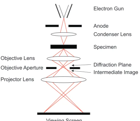
2.3.1 Transmission Electron Microscopy 52
2.3.1.1 Theory 53
2.3.1.2 Sample Preparation 56
2.3.2 Scanning Electron Microscopy 57
2.3.2.1 Theory 57
2.3.2.2 Sample Preparation 59
2.3.3 Energy-Dispersive X-ray Spectroscopy (EDX) 60
2.3.4 Scanning Transmission Electron Microscopy (STEM) 63
2.3.5 X-ray Diffraction (XRD) 63
2.3.5.1 Diffraction Theory 63
2.3.5.2 Powder X-ray Diffraction 69
2.3.5.3 PANalytical X’pert Pro Diffractometer 70
2.3.6 Thermogravimetric Analysis (TGA) 71
#!!!" 2.3.8 Inductively Coupled Plasma Atomic Emission
Spectroscopy (ICP-AES)
72
2.3.9 Piezoelectric Measurements 74
2.3.10 Infrared Spectroscopy 75
2.3.10.1 Theory 75
2.3.10.2 Fourier Transform Infrared Spectroscopy (FTIR) 77
2.3.11 Raman Spectroscopy 79
2.3.12 Gas Chromatography (GC) and CO Oxidation Catalysis Measurements
81
2.3.13 Nuclear Magnetic Resonance (NMR) 83
2.3.13.1 Theory 83
2.3.13.2 Solid State Nuclear Magnetic Resonance Spectroscopy (SSNMR)
86
2.3.14 SQUID 88
2.3.15 Measurement of the Magnetoelectric (ME) Effect 89
2.3.16 Gas Sorption 91
2.3.17 Ultraviolet and Visible Molecular Absorption Spectroscopy
97
2.3.18 Fluorescence Microscopy 97
References 98
Chapter 3
3 Synthesis and Characterisation of CoFe2O4 Nanoparticle CO Oxidation Catalysts
103
!$"
3.2 Experimental 105
3.2.1 Solvothermal Synthesis of Sample C1 105
3.2.1.1 Preparation of Cupferronate Precursors 106
3.2.1.2 Solvothermal Synthesis of CoFe2O4 106
3.2.2 Coprecipitation Synthesis of Sample C2 107
3.2.3 Synthesis of Samples C3-C8 108
3.2.4 Synthesis of Samples C9 and C10 109
3.2.5 Synthesis of NiFe2O4 Nanoparticles 109
3.2.6 Characterisation 110
3.2.6.1 Gas Sorption 110
3.2.6.2 X-ray Diffraction 110
3.2.6.3 Fourier Transform Infrared Spectroscopy 110
3.2.6.4 Thermogravimetric Analysis 111
3.2.6.5 Transmission Electron Microscopy 111
3.2.6.6 Elemental Analysis 111
3.2.6.7 Catalysis Testing 111
3.3 Results and Discussion 112
3.3.1 Synthesis and Characterisation of CoFe2O4 Nanoparticles
112
3.3.2 CO Oxidation Catalysis Testing 129
3.4 Conclusions 143
References 144
Chapter 4
$"
4.1 Introduction 148
4.2 Experimental 149
4.2.1 Preparation of 8 nm BaTiO3 (BTO) Nanoparticles 149
4.2.2 Preparation of 50 nm BTO Nanoparticles 149
4.2.3 Preparation of 200 nm BTO Nanoparticles 150
4.2.4 Preparation of BTO Nanowires 150
4.2.5 Preparation of 10 nm CoFe2O4 (CFO) Nanoparticles 151
4.2.6 Preparation of 12.5 nm CFO Nanoparticles 151
4.2.7 Functionalisation of BTO with 3-Phosphonopropionic Acid
152
4.2.8 Functionalisation of 10 nm Oleic Acid Terminated CFO Nanoparticles
152
4.2.9 Functionalisation of 12.5 nm CFO, 8 nm BTO Nanoparticles with APTMS
153
4.2.10 Electrostatic Assembly of BTO and CFO Nanoparticles (Route I)
153
4.2.11 DCCI Assembly of BTO and CFO Nanoparticles (Route II)
153
4.2.12 Preparation of BTO-CFO Control Composites (Route III)
154
4.2.13 Preparation of BTO-CFO NH2-NH2 Control Composite
154
4.2.14 Preparation of BTO-CFO NH3+-NH3+ Control Composite
$!"
4.2.15 Transfer of Assemblies from THF to H2O 154
4.2.16 Functionalisation of CFO with Thymine-1-Acetic Acid
154
4.2.17 Functionalisation BTO with 5’-Adenosine Monophosphate
155
4.2.18 Synthesis of Lucifer Yellow Tagged BTO Nanoparticles
155
4.2.19 Reaction of APTMS Modified BTO with Salicylaldehyde
155
4.2.20 Characterisation 156
4.2.20.1 X-ray Diffraction 156
4.2.20.2 TEM Imaging 156
4.2.20.3 SEM Imaging 156
4.2.20.4 FTIR Spectroscopy 157
4.2.20.5 Elemental Analysis 157
4.2.20.6 ICP-AES Analysis 157
4.2.20.7 Solid-State NMR 157
4.2.20.8 UV-Vis Molecular Absorption Spectroscopy 158
4.2.20.9 Fluorescence Microscopy 158
4.3 Results and Discussion 158
4.3.1 Synthesis and Functionalisation of 8 nm BaTiO3 Nanoparticles
158
$!!" Nanoparticles
4.3.4 Assembly of BTO (8 nm) – CFO (12.5 nm) Particles 172 4.3.5 Synthesis and Functionalisation of 10 nm CFO
Nanoparticles
174
4.3.6 Synthesis and Functionalisation of 50 nm Cube-like BTO Nanoparticles
178
4.3.7 Preparation of BTO (50 nm) – CFO (12.5 nm) “a” Assemblies
183
4.3.8 Functionalisation of 200 nm BTO Particles 190
4.3.9 Preparation of BTO (200 nm) – CFO (12.5 nm) “b” Assemblies
195
4.3.10 Further Control Reactions 197
4.3.11 Assembly using Biomolecules 199
4.3.12 Assembly of BTO Nanowires and CFO Nanoparticles 201
4.4 Conclusions 204
References 205
Chapter 5
5 Chemical Bond Assembled Multifunctional Oxide Nanocomposites
209
5.1 Introduction 209
5.2 Experimental 211
5.2.1 Preparation of BTO/CFO Ceramics 211
5.2.2 Processing of BTO/CFO Ceramics 211
$!!!"
5.2.4 Synthesis of 50 nm CFO Nanoparticles 212
5.2.5 Characterisation 212
5.2.5.1 X-ray Diffraction 212
5.2.5.2 TEM Imaging 212
5.2.5.3 SEM Imaging 213
5.2.5.4 Piezoelectric Constant Measurements 213
5.2.5.5 Measurement of the Magnetoelectric Coefficient (!E)
214
5.2.5.6 Fourier Transform Infrared Spectroscopy 214
5.2.5.7 Elemental Analysis 214
5.2.5.8 Thermogravimetric Analysis (TGA) 215
5.2.5.9 Raman Spectroscopy 215
5.2.5.10 SQUID 215
5.3 Results and Discussion 215
5.3.1 Preparation of BTO (50 nm) /CFO (10 nm) ‘A’ Ceramic Composites
215
5.3.2 The Piezoelectric Properties of 8, 50 and 200 nm BTO 220 5.3.3 Preparation and Characterisation of BTO (200 nm)
/CFO (12.5 nm) ‘B’ Ceramic Composites
226
5.3.4 Other Systems 246
5.3.5 Synthesis and Characterisation of a BTO (400 nm) /CFO (12.5 nm) ‘C’ Ceramic Composite
247
5.3.6 Hydroxylated BTO (200 nm) /CFO (12.5 nm) ‘D’ Ceramic Composites
$!#" 5.3.7 BTO (200 nm) /CFO (50 nm) ‘E’ Ceramic Composites 253
5.3.8 BTO (nanowire) /CFO (12.5 nm) ‘F’ Ceramic Composites
255
5.4 Conclusions 256
References 258
Chapter 6
Final Conclusions and Future Work 263
6.1 Final Conclusions 263
6.2 Future Work 266
References 268
#"
Chapter 1
1 Introduction
1.1
Early History of Nanoparticles
The history of nanotechnology dates back centuries. The Lycurgus cup held in the British Museum was made in the late Roman era; it is made of dichroic glass, which changes colour depending on whether light is shining onto it or through it. This property is due to the small amounts of gold and silver nanoparticles dispersed throughout the glass. The stained glass windows produced in the medieval period also made use of gold and silver nanoparticles, while the paints and glazes used by renaissance artists to colour pottery contained small amounts of copper and silver nanoparticles.1
$" This enabled the imaging and manipulation of individual atoms and the STM, like the electron microscope, has since proved crucial in advancing the field. Another major breakthrough was the discovery of fullerenes in 1985. These carbon-based materials continue to attract a huge amount of interest due to their potential to possess extraordinary strength and hardness, in addition to their electrical properties and chemical and heat resistance.2, 3
1.2 Recent Developments
The work detailed in this thesis concerns the synthesis and application of nanoparticles, small objects between 1 and 100 nm in diameter.4 They have potential technological applications stemming from their unique and often size-dependent properties, which means they can behave considerably differently to the bulk material.4, 5
%" The experimental challenge in the synthesis of nanoparticles lies in the preparation of uniform size and shape objects, which are important characteristics due to the size and shape dependence of, for example, their electrical, optical and magnetic properties.4 This is perhaps most easily illustrated by the fluorescent emission of quantum dots, which covers the entire visible spectrum as a function of their size.24 In the field of magnetic data storage, monodisperse nanoparticles are required due to the strong size-dependence of their magnetic properties.25, 26
A range of transition metal binary oxides have been prepared as nanoparticles. Sol-gel chemistry has been used to prepare 4 nm monodisperse ZrO2 nanoparticles from [Zr(OiPr)4] and ZrCl4 at 340 °C,27 while TiO2 was prepared by a similar route.28 Monodisperse MnO nanoparticles have been prepared by the thermal decomposition of manganese acetate in the presence of oleic acid at 320 °C.29 Others include Cu2O, NiO and ZnO; the latter finds use in the electronics industry, where it is used in liquid crystal displays.4
Complex oxides can also be prepared as nanoparticles.30 For example, Ni0.5Zn0.5Fe2O4 has been prepared between 9 to 90 nm by the coprecipitation of the corresponding metal nitrates with sodium hydroxide, with a subsequent calcination step. In this instance, the particle size was controlled by the calcination temperature, with sintering performed over a temperature range between 300 and 800 °C. The smaller particles were obtained by sintering at lower temperatures.31 Bi4Ti3O12 has been similarly prepared with sizes between 16 and 38 nm when sintering between 500 and 800 °C.32 The coprecipitation route used to prepare these materials is a flexible approach and a range of other complex oxides including 80 nm Sm1-xSrxFeO3-!,33 and 10 nm Ce0.8Y0.2O1.934 have also been prepared in this manner. The
&" metal oxide nanoparticles, and examples include 8 nm oleic acid functionalised CoAl2O4 prepared by Rangappa et al.35 (50 nm particles were prepared in the absence of oleic acid) and 35 nm LaCoO336 amongst others. The solvothermal approach is also attractive due to the prepared materials not requiring a post-synthesis calcination step, as is often the case with materials prepared by coprecipitation and sol-gel methods. This means the nanoparticle aggregation that can occur during these high-temperature steps is avoided, and a range of ferrites37, 38 and perovskites39 have been prepared by the solvothermal method. One issue that affects the chemical synthesis of nanoparticles, and one that must be tackled in order increase their application is the small scale at which these reactions are typically carried out. Continuous flow solvothermal reactors are one way in which this is being addressed, and these have been used to prepare a range of materials including BaTiO3, TiO2, Fe3O4 and Ce1-xZrxO2 nanoparticles.40 The theory behind the synthesis of metal oxide nanoparticles by routes such as coprecipitation and sol-gel is described in more detail in Chapter 2.
'" nanowires of BaTiO3 prepared via a mixed solvothermal and ion exchange approach.45
1.3 CoFe2O4
1.3.1 Structure and Properties
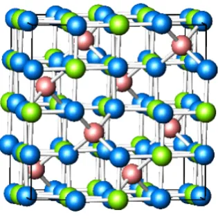
CoFe2O4 nanoparticles are one of the materials prepared in the work described in this thesis. It is a transition metal oxide that adopts the inverse spinel structure; the Co2+ cation occupies one half of the octahedral coordination sites, with the Fe3+ cations occupying the remaining octahedral coordination sites in addition to the tetrahedral coordination sites. This is different to the normal spinel structure (AB2O4) were the A2+ and B3+ cations occupy the tetrahedral and octahedral sites respectively. The crystal structure of CoFe2O4 is shown in Figure 1.
[image:20.595.231.389.470.629.2]
(" CoFe2O4 is a ferrimagnetic oxide that has a net magnetisation of approximately 1 Bohr Magneton per metal ion and a bulk magnetisation of 425 emu cm-3 (80.34 emu g-1, 18,850 emu mol-1) at 300 K. It has a lower conductivity than Fe3O4, which is also ferrimagnetic, and which has a full complement of octahedral B-site Fe2+ ions that can transfer electrons among the Fe3+ neighbours in the B sublattice. Its magnetisation is higher than that of CoFe2O4, with a net magnetisation of 4/3 Bohr Magnetons per metal ion and a magnetisation of 480 emu cm-3 (91.60 emu g-1, 21,208 emu mol-1) at 300 K. For comparison, iron has a magnetisation of 1,713 emu cm-3 (217.6 emu g-1, 95,683 emu mol-1) and Fe3C has a magnetisation of 1,082 emu cm-3 (140 emu g-1, 25,135 emu mol-1).46 In most ferrites (spinels were Fe is on the B-site) the electronic interaction in bonding is such that there is little electron orbital momentum (orbital quenching). The main contribution to the magnetic moment is from the electron spins that are not cancelled by antiparallel spins on other sublattices and are free to orient with the applied magnetic field.47, 48
The magnetisation behaviour of magnetic nanoparticles including CoFe2O4 can be markedly different to that of the bulk. In large magnetic particles there is a multidomain structure where regions of uniform magnetisation are separated by domain walls. The formation of the domain walls is a process driven by the balance between the magnetostatic energy ("EMS), which increases proportionally with the
particle size, and the domain-wall energy (Edw), which increases proportionally with the interfacial area between domains. There is a critical size below which it costs more energy to create a domain wall than it does to support the external magnetostatic energy (stray field) of the single-domain state ("EMS=Edw). This
)" in the same direction and the magnetisation will be reversed by spin rotation since there are no domain walls to move. This is the reason for the very high coercivity observed in small nanoparticles.49
The second important phenomenon that occurs in magnetic nanoparticles is superparamagnetism. The energy barrier KeffV (where Keff is the anisotropy constant and V is the particle volume) separates the two energetically equivalent easy directions of magnetisation. With decreasing particle size, the thermal energy, kBT (where kB is the Boltzmann constant and T is the temperature) exceeds the energy barrier KeffV and the magnetisation is easily flipped. In this situation the system behaves like a paramagnet, and instead of atomic magnetic moments there is now a giant (super) moment inside each particle. This system is named a superparamagnet, it has no hysteresis and the data of different temperatures superimpose onto a universal curve of M versus H/T. This is illustrated in Figure 2 below.
Figure 2. An illustration of the magnetic moments in a ferromagnet (left) and superparamagnet (right), which exists below the critical size Dc. Illustrative M vs. H magnetisation curves are shown for each, note that there is no hysteresis in the magnetisation of a superparamagnet.49
M
H
M
H D < Dc
Ferromagnet Superparamagnet
*" The critical size below which CoFe2O4 is superparamagnetic is around 10 nm.49-51 This critical size depends on a number of factors including the value of the magnetic saturation, the strength of the crystal anisotropy, surface and domain-wall energy and the shape of the nanoparticles.52
The application of an alternating external magnetic field to superparamagnetic nanoparticles leads to the generation of heat from the thermal fluctuations that occur as the spins overcome their blocking energy barrier and flip with the alternating magnetic field. Colloidal suspensions of superparamagnetic CoFe2O4 nanoparticles are consequently candidate materials for hyperthermia based cancer treatments.53 CoFe2O4 is also finding use in ferrofluids, where small nanoparticles, stabilised by hydrophobic or hydrophilic molecules, are dispersed in organic solvents or water. The colloidal stability of these nanoparticles enables their manipulation by an external magnetic field, without separation of the nanoparticles from the solvent. Ferrofluids have applications in areas ranging from the electronics industry, where they are used to form liquid seals around the spinning drive shafts in hard disks; to medicine, where they are useful as contrast agents in magnetic resonance imaging (MRI).
The magnetostrictive properties of CoFe2O4 are also of importance. Materials based on the phenomenon of magnetostriction are used for vibration control and ultrasonic generation and detection, and there is scope for their use in automotive and aerospace applications.53, 55 Magnetostriction, !, is defined as the contraction or expansion of a
!+" mechanisms mean the material can change the domain orientation and this, in turn, causes a dimensional change. It is measured as the % strain, ! = "l/l0, where l0 is the length of the material along a given direction in the un-magnetised state, and "l is the resulting strain. ! can be positive or negative, depending on whether the effect is expansive or compressive. The saturation or engineering magnetostriction constant, !s, corresponds to the maximum % strain, and usually appears at the saturation field Hs.57
CoFe2O4 has amongst the highest values for magnetostriction for magnetic oxides58 and due to this, and the properties and applications discussed earlier, much research has been directed towards the controlled synthesis of CoFe2O4 nanoparticles in order to maximise their utility.
1.3.2 Synthesis
!!"
Figure 3. TEM images of oleic acid stabilised CoFe2O4 nanoparticles prepared by Xie et al.60"a) 5 nm CoFe2O4 prepared using 20 mL benzyl ether, b) ~11 nm CoFe2O4 prepared in 20 mL octadecene, and c) ~14 nm CoFe2O4 prepared in 10 mL 1-octadecene in the presence of 2 mmol of glucose.
Coprecipitation is a commonly used method for ferrite synthesis as the reactions can be easily scaled to afford gram quantities of nanoparticles at low temperature. Ghosh et al. demonstrated the synthesis of CoFe2O4 by coprecipitation.61 This approach involved the aqueous hydrolysis of the metal chloride salts at 80 °C in the presence of the surface stabilising molecules CTAB and n-octylamine which act to prevent nanoparticle aggregation and growth. A whole range of other synthetic approaches are used for the synthesis of CoFe2O4 nanoparticles, and they enable control of the nanoparticle size, morphology, magnetic properties and surface chemistry; these include solvothermal,38 sol-gel62 and template63 based approaches.
1.4 CO Oxidation
Nanoparticles were used as CO oxidation catalysts in the work described in this thesis and they have been used as catalysts in heterogeneous systems since the 19th century.64 Today, many heterogeneous catalysts contain supported nanoparticles of
!#" the active material in order to optimise their utility, the Cu/ZnO methanol synthesis catalyst is once such example.65 Nanoparticle catalysts are utilised on a large scale to produce plastics and pharmaceuticals, as well as for environmental applications, such as the removal of NOx pollutants from vehicle exhausts by noble metal nanoparticle
catalysts.66
CO oxidation catalysts are much sought after for the removal of CO in vehicle exhaust emissions, respirators and in H2 rich gas feeds used for fuel cells, amongst
other areas.67-69 CO oxidation is a relatively straightforward reaction; it is irreversible at low temperatures and goes without parallel or secondary reactions, and consequently it is also one of the basic model reactions for heterogeneous catalysts. CO oxidation over metal oxides is thought to follow the stepwise mechanism first suggested by Mars and van Krevelen in 1954.70 It occurs in two steps; firstly, CO is oxidised by the surface lattice oxygen atoms in the metal oxide, which leads to the creation of an oxygen vacancy, and this leads to the reduction of the neighbouring metal ions to a lower oxidation state. In the second step the surface metal atoms are re-oxidised by gas phase oxygen. This is illustrated below:
CO + Ocat→ CO2,ads + * (1.1)
CO2,ads → CO2(g) (1.2)
!O2 + * → Ocat (1.3)
Where * depicts an oxygen vacancy and Ocat is surface lattice oxygen.
!$"
Transition metal oxides are, consequently, amongst the most studied and active metal oxide CO oxidation catalysts due to their ability to readily change oxidation state. One presently used CO oxidation catalyst is hopcalite, CuMn2O4, which was first
reported in 1921.71-73 Hopcalite is an active catalyst at room temperature and at elevated temperatures, though it is known to undergo deactivation under humid
conditions.74 Co3O4 is another active metal oxide CO oxidation catalyst. It has also
been shown to be active below room temperature75, 76 in both its supported and unsupported forms though, like hopcalite, it undergoes deactivation in the presence
of moisture.
Perhaps the most studied CO oxidation catalysts in recent years have been supported
Au nanoparticles. The review by Haruta77 explored the size and support dependence of the activity of Au nanoparticles in a number of reactions including CO oxidation. Supported Au nanoparticles are highly active CO oxidation catalysts, converting
100% CO to CO2 below room temperature, though above a critical size of
approximately 8 nm Au nanoparticles are inactive.78, 79 This means they can be prone
to deactivation by sintering and are usually considered unsuitable for applications above room temperature. In addition, Au nanoparticles are not active catalysts in the absence of the support, and there has been much investigation into why this is the
case, and what the precise role of the support is.80
Pirogova et al.81 demonstrated the potential of ferrites as CO oxidation catalysts.
They investigated the temperature dependent activity of materials including bulk CuFe2O4, CoFe2O4 and NiFe2O4, and these showed temperatures of 50% conversion,
T50, of 115, 165 and 215 °C respectively. While catalysts with this level of activity
!%" Au nanoparticle catalysts are not suitable due to their deactivation upon sintering.
1.5 BaTiO
31.5.1 Introduction
Much of the work detailed in this thesis involves nanometric BaTiO3, and what follows is an introduction to its synthesis and properties.
Ferroelectrics were first discovered by Valasek in 1920, though up until 1943 they were thought to be of little practical application due to their water solubility and fragility. That was changed by the discovery of BaTiO3.85 The structural simplicity of BaTiO3 encouraged theoretical work and its physical properties ultimately helped lead to the creation of the electronic ceramics industry.
Because of the high cost of single crystals, ferroelectric devices were initially limited
to bulk ceramics. They found application as piezoelectric transducers, actuators and
for pyroelectric detectors. However, there was a change of focus following the
integration of ferroelectric thin-films into semiconductor chips,86 and it was in the form of integrated ferroelectrics that the renaissance of ferroelectric materials
occurred.
Ferroelectrics are materials whose intrinsic lattice polarisation P can be reversed through the application of an external electric field E that is greater than the coercive
field Ec. They tend to possess a phase-transition, or Curie temperature Tc, above which they are paraelectric. All ferroelectrics are also pyroelectric (though the
reverse is not true), and all pyroelectrics are piezoelectric. Ferroelectrics cannot
possess a centre of symmetry and most ferroelectric families are not oxides, though
!&" There are, at present, a number of directions for ferroelectrics research. These
include studying their synthesis in nanowire and nanotube morphologies,
investigating their finite size effects and their use in magnetoelectric composites, as
well as researching their application in areas such as in ferroelectric random access
memories (FeRAMs).88
1.5.2 Structure and Application of BaTiO3
Barium titanate (BaTiO3) is a ferroelectric oxide with the perovskite structure that
undergoes a transition from a ferroelectric tetragonal phase to a paraelectric cubic phase upon heating above 130 °C. In the cubic phase, the structure of which is
displayed in Figure 4a, titanium atoms are octahedrally coordinated by six oxygen atoms.
"""""""""
Figure 4. The structure of barium titanate, BaTiO3 in a) the paraelectric cubic form,
space group Pm-3m and b) the ferroelectric tetragonal form, space group P4mm.89
Ferroelectricity arises in tetragonal BaTiO3 due to an average relative displacement
along the c-axis of titanium from its centrosymmetric position in the unit cell, and
!'"
consequently the creation of a permanent electric dipole. The tetragonal unit cell is
shown in Figure 4b. The elongation of the unit cell along the c-axis and the deviation of the c/a ratio from unity can be used as an indication of the presence of the ferroelectric phase.90-92",-."/0rroelectric properties and high dielectric constant make
BaTiO3 useful in an array of applications such as in multilayer ceramic capacitors,
gate dielectrics,"waveguide modulators,IR detectors, and holographic memory.93
1.5.3 Size-Property Relationship
The dielectric and ferroelectric properties of BaTiO3 are known to correlate with
size, and the technological trend toward decreasing dimensions means this correlation has been closely examined at the nanoscale,94, 95 with the ferroelectric
phase observed to become unstable at room temperature when particle diameter decreases below a critical size. This critical size is sensitive to a number of parameters including: composition, strain, lattice defects, and surface charge.96
Due to the differences in the cell parameters of the tetragonal and cubic phases being small compared to the broadening on the XRD peaks, which occurs as a result of the small particle size, there is likely an overestimation of the critical size from diffraction studies. Fong et al. performed work on the perovskite PbTiO3 showed
!("
BaTiO3 sphere to be 4.2 nm.96 X-ray diffraction (XRD) studies are consistent with an
increasingly cubic structure at smaller particle sizes, not distinguishing between
average and local structure,98 and Raman results have supported the existence of
tetragonal symmetry at small dimensions, even when the XRD was unable to detect
it.99
The dielectric and piezoelectric constants are also strongly size-dependent and vary with the same parameters discussed for the size-structure relationship (composition,
lattice defects, surface charge). While the piezoelectric properties tend to diminish with particle size, Wada et al.89 have recently demonstrated the preparation of BaTiO3 particles with very few lattice hydroxyl groups via a two-step thermal
decomposition method from barium titanyl oxalate. The dielectric constant of the impurity-free BaTiO3 fine particles increases with their decreasing size in the range
from 430 to 140 nm but decreases from 140 to 40 nm.
1.5.4 Synthesis
Many strategies have been deployed for the synthesis of well-defined nanometric
BaTiO3. Hou et al.100 recently demonstrated the solvothermal synthesis of cube-like
BaTiO3 nanoparticles on the order of 50 nm, while Kang et al. have demonstrated the
synthesis of well-defined nanowires from the ion-exchange reaction between
K2Ti4O9 nanostructures and barium hydroxide.45 Finally, Niederberger et al. reported
a solvothermal preparation of 5 nm particles of BaTiO3 and SrTiO3 from titanium
isopropoxide and metallic barium or strontium in benzyl alcohol,101 with TEM
!)"
[image:32.595.227.372.68.311.2]
Figure 5. TEM images of 5 nm BaTiO3 nanoparticles prepared by Niederberger et
al. a) An overview image a showing non-aggregated BaTiO3 nanoparticles; b)
selected area electron diffraction (SAED) and c), d) high resolution TEM images of
isolated BaTiO3 nanocrystals.101
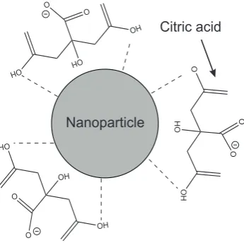
1.6 Nanoparticle Functionalisation
Chemical functionalisation of the external surfaces of nanoparticles enables
modification of properties including the charge, functionality, reactivity, stability and
dispersibility,102, 103 and this is explored in some the work described in this thesis.
Functionalisation can also be used to provide nanoparticles with magnetic, optical or
catalytic properties.104, 105 The controlled coating of nanoparticles with organised
layers is technically challenging due to the possibility of the functionalised
nanoparticles agglomerating with one another, thus limiting their utility. There has,
however, been considerable progress in recent years in the development of This Figure can be seen in
!*" nanoparticles functionalised with polymers, biomolecules and small organic and
inorganic functionalities.
Polymer coated nanoparticles have found application in the manufacture of inks and
paints,105 and in biological applications where they have been used to enhance the
biocompatibility of nanoparticles.106 This type of functionalisation is performed
either by polymerisation on the particle surface,107 or via adsorption of polymers to
the surface.108 The former has been illustrated by the preparation of poly(pyrrole)
coatings on #-Fe2O3 and CeO2. This was performed by using the oxide surface
species to drive the polymerisation of pyrrole on the particle surface, and these
functionalised nanoparticles were found to be electrically conductive.109 An example
of the adsorption of polymer layers onto the particle surface is the preparation of
polymer-stabilised Ag nanoparticles, where the encapsulation of individual Ag
nanoparticles was demonstrated with polystyrene and methacyrlate.110 The
disadvantage of this method is the potential for nanoparticle aggregation inside the
polymer matrix.
Particles that are functionalised with biomolecules can be engendered with the ability
to target specific cells, antigens or virus molecules. They can also have prolonged
circulation in the blood and be used for intercellular drug-delivery.103 The most
common method involves non-covalent binding of the biomolecules to the particle
surface, for instance through electrostatic interactions. Bovine serum albumin (BSA)
and immunoglobulin G (IgG) have been deposited on polystyrene microspheres by
the alternate deposition of the protein and oppositely charged polymer.111
Small organic and inorganic molecules can also be used to functionalise nanoparticle
surfaces. Generally, these are adhered to the surface of pre-formed nanoparticles by
#+"
precipitation of tetraethoxysilane (TEOS) on the nanoparticle surface.112 Surface reactions enable species such as silane molecules to be chemically grafted to metal
oxide nanoparticle surfaces via the formation of M-O-Si bonds, and this type of
functionalisation has been applied to Fe3O4 nanoparticles.113 De Palma et al.114 illustrated the anchoring of a whole host of functional silane molecules to the surface
of Fe3O4 via a ligand exchange reaction, where the electrostatically bound oleic acid
functionalities were replaced by chemically bound silane molecules. This enabled
modification of the nanoparticles solubility and other properties, with the goal of
enhancing the nanoparticles biocompatibility whilst taking advantage of the
monodispersity that large stabilising molecules such as oleic acid can provide.
Chemical binding of functional molecules to oxide nanoparticle surfaces is not
limited to silanes, though these are the most studied materials at present. Kim et al.102 and others115 have demonstrated the anchoring of phosphonic acid molecules using the same principle, though in this case weaker M-O-P bonds are formed
between the functional organic molecules and the nanoparticle surfaces. This has
potential application in the preparation of new dielectric materials with high
permittivity and dielectric strength, for application in capacitors amongst other
areas.102
1.7 Nanoparticle Assembly
The assembly of different phases of nanoparticles with one another is discussed in
this thesis, and leads to the generation of arrays with combinations of interacting
#!" that promotes the formation of structures with, for instance, face centred cubic (fcc)
ordering and such chemistry has been applied to the synthesis of Au–#Fe2O3 and
Au–PbSe nanoparticle arrays121 and structures including Pd, Ag and $-Fe2O3.122
TEM images of a selection of these structures can be seen in Figure 6.
Figure 6. TEM images of BNSLs assembled from different nanoparticles, and
modelled unit cells of the corresponding three-dimensional structures. The
superlattices are assembled from a) 13.4 nm $-Fe2O3 and 5 nm Au; b) 7.6 nm PbSe
and 5 nm Au; c) 6.2 nm PbSe and 3.0 nm Pd.122
The formation of BNSLs can be driven by a number of forces including purely by
entropy;123 though in some cases, where entropy alone is not thought to be sufficient, Coulomb, van der Waals, charge-dipole and dipole-dipole interactions are thought to
play a role.121
Chemical functionalisation of the external surfaces of nanoparticles also allows for
the assembly of multiple phase arrays and this approach is not particle size limited,
as is the case for the BNSLs.124, 125 Galow et al. have demonstrated the assembly of Au–SiO2 aggregates via electrostatic interactions between the functionalised,
positively charged SiO2 nanoparticles and"the functionalised, negatively charged
[image:35.595.113.525.204.359.2]##" Au.117 This is illustrated in Scheme 1 below. The authors used an aminosilane to
engender the SiO2 nanoparticles with terminal amine functionalities, while a
bi-functional thiol, 11-mercaptodecanoic acid, was used to provide carboxylic acid
functionalities on the Au nanoparticle surfaces.
Scheme 1. An illustration of carboxylic acid functionalised Au 1 reacting with amine
functionalised SiO2 2 to produce, depending on the ratio in which they are mixed,
Au-SiO2 assemblies 3 and 4.117
Bi-functional thiolates are commonly used for the assembly of noble metal
nanoparticles. Sendroiu et al. demonstrated the assembly of Ag and Au nanoparticles
using thiol functionalised nanoparticles and a Co(II) complex,124 while Mirkin et al.
assembled Au nanoparticles using complementary strands of DNA, tethered to the
nanoparticle surface though thiol linkages.126
The assembly of nanostructures is not limited to the spherical nanoparticles. In their This Scheme can be seen in reference 117
#$"
work, Rycenga et al.127 demonstrated the assembly of Ag nanocubes. This was
achieved bythe selective functionalisation of the cube faces with either hydrophobic
or hydrophilic functionalities. This approach enabled the authors to prepare a range
of different nanostructures and an extended three-dimensional microstructure,
depending on which faces of the nanocubes were functionalised.
The synthesis of metal oxide nanoparticle assemblies is challenging due to the
functionalisation chemistry being less well developed than for Au and Ag
nanoparticles, for which an array of bi-functional thiolates are commercially
available.128 In one example, a purely complex metal oxide nanoparticle assembly
was been demonstrated by Mornet et al.119 They used electrostatic assembly to
prepare BaTiO3/PZT – $Fe2O3 hybrids, a TEM image of which can be seen in Figure
7.
Figure 7. TEM image of a ‘nano-raspberry’ prepared from BaTiO3@SiO2 core
surrounded by $-Fe2O3@SiO2 nanoparticles.119
In this instance the authors used aminosilane functionalised BaTiO3@SiO2 or
PZT@SiO2 nanoparticles and assembled them with $-Fe2O3@SiO2. The partial
positive charge on the former interacted with the partial negative charge of the latter
[image:37.595.220.409.425.586.2]#%"
to produce the afore mentioned assemblies.
1.8
Multiferroics and Magnetoelectrics
1.8.1 Introduction
Magnetoelectric composites were prepared in the work described in this thesis, and
what follows is an introduction to multiferroics and magnetoelectric materials.
The original definition of a single-phase multiferroic material was one in which two
or more of the ‘ferroic’ properties: ferroelectricity, ferromagnetism and
ferroelasticity existed, though this definition has since been expanded to include the
possibility of materials possessing ferrotoroidicity. Single-phase materials in which
ferromagnetism and ferroelectricity arise independently remain rare. The reason for
this was discussed by Hill et al., who found that conditions required for the
coexistence of ferroelectricity and ferromagnetism in single phase materials are
rarely met.129 Cation off-centring in ferroelectrics (which requires formally empty
d-orbitals) and the formation of magnetic moments (which usually requires partially
filled d-orbitals)129, 130 mean that, for ferroelectricity and magnetism to coexist in a
single phase, the atoms that move off centre to form the electric dipole must be
different to those carrying the magnetic moment. This can only be achieved though a
non-d-electron mechanism for magnetism, or though an alternative mechanism for
ferroelectricity, with the latter pursued for the synthesis of a new generation of
single-phase multiferroics.
Magnetoelectric (ME) coupling describes the influence that an applied magnetic (or
#&" materials, it is possible to generate an electric polarisation via the application of an
external magnetic field, or vice versa. ME coupling may exist whatever the nature of
the magnetic and electrical order parameters, and has been observed in paramagnetic
ferroelectrics,131 though the effect does require the phase(s) to be both electrically
and magnetically polarisable. The overlap between multiferroic and magnetoelectric
materials is illustrated in Figure 8.
Figure 8. The relationship between multiferroic and magnetoelectric materials. The
red intersection represents materials that are multiferroic, while magnetoelectric
coupling is an independent phenomenon that can, but need not, arise in any of the
materials that are both magnetically and electrically polarisable. In practice, it is
likely to arise in all such materials, either directly or via strain.132
ME coupling may arise directly between the two order parameters, or in materials
where the magnetic and electrical order parameters exist in separate but intimately
#'"
ME materials have potential application in electronic devices such as transducers,
magnetic field sensors and in the information storage industry. One target regards
their deployment in the development of multiple-state memory devices, where data
could be written electrically, and, owing to the coupling of the electric and magnetic
parameters, read magnetically. It relies on the reversal of the magnetisation by the
application of a magnetic field (or vice versa), which is termed magnetoelectric
switching, and this is potentially attractive as it would enable exploitation of the best
aspects of ferroelectric random access memory (writing) and magnetic data storage
(reading), while avoiding the problems associated with reading FeRAM and
generating large local magnetic fields needed to write magnetically. However, there
is still work to be done in preparing the magnetoelectric materials that could make a
major contribution to the data storage industry, therefore, in the short term, niche
applications of magnetoelectric materials are likely to emerge, such as in sensors,
microwave devices and transducers.132
As previously stated, single-phase multiferroics and magnetoelectrics are rare,
however two-phase systems of, for example, ferroelectric and ferromagnetic
materials can also possess magnetoelectric properties via strain-coupling of the two
orders. ME composites were dealt with in detail by Nan et al. in their recent
review.133 The advantages of ME composites over their single-phase counterparts
include greater design flexibility, and the potential for larger ME coefficients, with
the best ME composites possessing ME coefficients several times larger than those
observed in single-phase materials.134
Much research has been done on ME composites over recent years due to the
technologically viable response observed for some of these materials above room
#("
and ferrites,135, 136 two-phase composites of magnetic alloys and piezoelectrics137, 138
and nanostructured thin films.139, 140
ME composites are generally described in terms of the connectivity of the phases, a
concept which was introduced by Newnham et al.141 The connectivity of three of the
most common types of bulk ME composite are shown in Figure 9 below. For
instance, the connectivity type noted as 0-3 indicates a composite of particles (0)
embedded in a matrix of another phase (3).
Figure 9. Illustration of bulk ME composites with three of the most common
connectivity schemes: 0-3 particulate composite (left), 2-2 laminate composite
(centre) and 1-3 fibre/rod composite (right).133
The magnetoelectric coupling can be measured indirectly by recording changes in
the magnetisation at or near the Curie temperature of the ferroelectric material, or
changes in the dielectric constant near a magnetic transition temperature. The
resulting effects are termed the magnetocapacitance and magnetodielectric response.
However, while more challenging, it is much more useful perform direct
measurements where, for example, the electrical response to an applied magnetic
#)" voltage is measured using the former technique, empirical coupling coefficients,
termed #E are obtained and the magnitude of #E is often used when comparing
materials with one another.133
1.8.2 Bulk Ceramic Magnetoelectric Composites
What follows is an introduction to bulk ceramic ME composites, and these materials
have been prepared with 0-3 and 2-2 type connectivities. The discussion is centred
on materials where a piezoelectric phase such as BaTiO3 or PZT is mixed with a
ferromagnetic phase, such as CoFe2O4, as it is these types of materials that are
developed and discussed in this thesis.
The original work on the in situ formation of the ME ceramic composites was
performed at Philips Laboratories,142-144 were a magnetoelectric coefficient, #E, of 50
mV cm-1 Oe-1 was measured for a composite prepared via the unidirectional
solidification of a eutectic composition of the quinary system Fe–Co–Ti–Ba–O.
Subsequent work on a eutectic composition of BaTiO3–CoFe2O4 prepared by
unidirectional solidification lead to an increase of #E to 130 mV cm-1 Oe-1.
Unidirectional solidification requires precise control over composition, and this can
be difficult, especially when one of the components is a gas (oxygen). Consequently
the majority of research was targeted at the development of ME ceramic composites
via sintering, which is both an easier and cheaper method for the fabrication of
ceramic ME composites of piezoelectrics and ferrites.
In the early 1990s much work was done on the preparation of particulate ceramic
composites (materials comprised of piezoelectric and ferromagnetic particles) of
#*"
particulate composite ceramics were considered small at around 1 mV cm-1 Oe-1
orders of magnitude.145, 146 However, by controlling the relative amounts of the
ferroelectric and ferromagnetic phases, using ferroelectric and ferromagnetic phases
with the most favourable properties (such as ferroelectrics with high piezoelectric
constants, and ferromagnetic materials with large magnetisations and
magnetostriction) and using sintering temperatures and times that optimised the
density and phase purity, coefficients of around 10–100 mV cm-1 Oe-1 were
eventually obtained.147
The magnitude of #E was found to be strongly dependent on the sample sintering
temperature. Work by Ryu et al. demonstrated this,147 with the authors showing the
properties of PZT/NiFe2O4 composites with respect to sample composition and
sintering temperature. A ME coefficient of 115 mV cm-1 Oe-1 was reported, and the
large ME coefficient was attributed to a homogeneous and well-dispersed
microstructure, and the large grain size of the matrix PZT phase.
So far, it has proven difficult to match the values of #E predicted by theoretical
calculations with the experimental results. This is thought to be partly due to
inter-diffusion between the piezoelectric and ferrite phases during the high-temperature
sintering step, which leads to the formation of unwanted phases; and to thermal
expansion mismatch between the two phases, which harms the densification process
and leads to microcracks forming within the sample during sintering. The
low-resistivity ferrite phase also tends to reduce the efficiency of the necessary electrical
polarisation of the ferroelectric phase, and leads to leakage of the piezoelectrically
stored charge. All of these factors mean it has not been possible to observe the large
ME coefficients predicted for materials with a larger than 0.5 mole fraction of
$+"
Recently, hot pressing148and spark plasma sintering149(SPS)have been employed to
address the inter-diffusion problem. The short time and low temperature required for
densification during SPS reduces the chance for unwanted phases to form, and
hot-pressed and SPS processed samples have been found to display an increased #E when
compared to the conventionally sintered samples. For example, PZT/NiFe2O4
composite ceramics with densities of 99% of the theoretical maximum have been
prepared using SPS,149and these materials have improved ME coefficients (~ 26 mV
cm-1 Oe-1) when compared analogous ceramics prepared via traditional sintering
techniques (~ 18 mV cm-1 Oe-1).
The leakage problem due to the low resistivity ferrite in the 0-3 and 1-3 type
composite ceramics can be eliminated in 2-2 laminate composite ceramics. They are
generally prepared by co-firing piezoelectric and ferrite layers at high temperature,
with a ME coefficient of 400 mV cm-1 Oe-1 measured for a PZT/NiFe2O4 layered
composite.150, 151
1.8.3 Nanostructured Thin Films
Nanostructured composite thin films of ferroelectric and magnetic oxides have
recently been prepared by pulsed laser deposition (PLD),139 spin coating and sol-gel
methods. Nanostructuring enables greater control of the interface between the FE and
FM components. It also enables the physical mechanism of the ME coupling effect to
be examined at the nanoscale, and could lead to the application of ME materials in
microelectronic devices.
Zheng et al. used PLD to synthesise composites of BaTiO3 and CoFe2O4 with the 2-2
$!"
Figure 10. In the case of the 1-3 composite, 20-30 nm rods of CoFe2O4 were
embedded into a BaTiO3 matrix. The generation of large ME coefficients is believed
to be possible in systems with this type of connectivity, and this was recently
demonstrated though switching of the magnetisation on reversal of the ferroelectric
polarisation,152 which was attributed to efficient strain coupling resulting from the large interfacial surface area. However, whilst ME coupling has been observed in
these systems via microscopy,153 ME coefficients have not been directly measured because of the leakage resulting from the low resistance ferrite rods penetrating
though the film. Consequently, much work remains to be done to exploit the large
ME coupling that these systems possess.
[image:45.595.142.492.377.608.2]
Figure 10. a) Superlattice of a spinel (top) and a perovskite (middle) on a perovskite substrate (bottom). b) Schematic illustration of a multilayer 2-2 structure on a
substrate. c) Epitaxial alignment of a spinel (top left) and a perovskite (top right) on a
perovskite substrate (bottom). d) Schematic illustration of a self assembled 1-3
nanostructured thin film formed on the substrate.139
$#"
1.9 Aims of This Thesis
The first aim of this thesis was to prepare controlled size CoFe2O4 nanoparticles and
investigate their activity as CO oxidation catalysts, in the knowledge that CoFe2O4
had been shown to be a promising catalyst by Pirogova et al.81 It was thought that a
reduction in the nanoparticle size could lead to the enhancement of the catalyst
activity, and so a synthetic protocol for the preparation of CoFe2O4 nanoparticles
with a range of controlled sizes was to be developed prior to testing their activity.
The second aim was to investigate the formation of functional hybrid nanostructures
between metal oxide nanoparticles of the ferromagnetic/superparamagnetic CoFe2O4
and the ferroelectric BaTiO3, and in doing so, to provide a general approach by
which nanoparticle oxides could be functionalised and assembled with one another to
form multifunctional nanomaterials. The small amount of literature on the assembly
of metal oxide nanoparticles, and the potential applications for mixed metal oxide
nanoparticle hybrids drove this aspect of the work. The third aim was to utilise this
nanoparticle assembly chemistry to develop magnetoelectric composites of BaTiO3
and CoFe2O4 nanoparticles. The potential for larger interfaces between the
ferroelectric and ferromagnetic phases in these materials than in those prepared via
the traditional grinding and firing approach could potentially produce larger
magnetoelectric effects, and be a step towards the making the widespread use of
magnetoelectric materials a reality.
References
$$"
2. J. P. Srivastava, Elements of Solid State Physics, PHI Learning LTD., 2006.
3. Y. Gogotai, Nanomaterials Handbook, CRC Press, 2006.
4. J. Park, J. Joo, S. G. Kwon, Y. Jang, T. Hyeon, Angew. Chem. Int. Ed. 2007,
46, 4630.
5. D. L. Huber, E. L. Venturini, J. E. Martin, P. P. Provencio, R. J. Patel, J.
Magn. Magn. Mater. 2004, 278, 311.
6. X. Wang, J. Zhuang, Q. Peng, Y. Li, Nature 2005, 437, 121.
7. F-Y. Cheng, C-H. Su, Y-S. Yang, C-S. Yeh, C-Y. Tsai, C-L. Wu, M-T. Wu,
D-B. Sheih, Biomaterials 2005, 26, 729.
8. Y. Xie, C. Yuan, Appl. Cat. B. 2003, 46, 251.
9. H. Herrig, R. Hempelmann, Mater. Lett.1996, 27, 287.
10. T. J. Daou, G. Pourroy, S. Bégin-Colin, J. M. Grenèche, C. Ulhaq-Bouillet, P.
Legaré, P. Bernhardt, C. Leuvrey, G. Rogez, Chem. Mater. 2006, 18, 4399.
11. X-M. Zhao, Y. Xia, G. M. Whitesides, J. Mater. Chem. 1997, 7, 1069.
12. H. Cao, Z. Yu, J. Wang, J. O. Tegenfeldt, R. H. Austin, E. Chen, W. Wu, S.
Y. Chou, Appl. Phys. Lett. 2002, 81, 174.
13. A. Zaluska, L. Zaluski, J. O. Ström-Olsen, J. Alloys Compd. 1999, 288, 217.
14. Y. A. Kim, T. Hayashi, Y. Fukai, M. Endo, T. Yanagisawa, M. S.
Dresselhaus, Chem. Phys. Lett. 2002, 355, 279.
$%"
16. S. H. Joo, S. J. Choi, I. Oh, J. Kwak, Z. Liu, O. Terasaki, R. Ryoo, Nature
2001, 412, 169.
17. J. L. Mohanan, I. U. Arachchige, S. L. Brock, Science2005, 307, 397.
18. N. L. Pickett, P. O’Brien, Chem. Rec. 2001, 1, 467.
19. K. L. Stamm, J. C. Garno, G. Liu, S. L. Brock, J. Am. Chem. Soc. 2003, 125,
4038.
20. J. F. Janik, Powder Tech. 2005, 152, 118.
21. P. Banerjee, B. M. Mandal, Macromolecules1995, 28, 3940.
22. M. S. Cho, S. Y. Park, J. I. Huang, H. J. Choi, Mater. Sci. Engi. 2004, 24, 15.
23. C. N. R. Rao, S. R. C. Vivekchand, K. Biswas, A. Govindaraj, Dalton Trans.
2007, 3728.
24. A. L. Rogach, D. V. Talapin, E. V. Shevchenko, A. Kornowski, M. Haase, H.
Weller, Adv. Funct. Mater. 2002, 12, 653.
25. T. Hyeon, Chem. Commun. 2003, 8, 927.
26. S. Sun, C. B. Murray, D. Weller, L. Folks and A. Moser, Science 2000, 287,
1989.
27. J. Joo, T. Yu, Y. W. Kim, H. M. Park, F. Wu, J. Z. Zhang, T. Hyeon, J. Am.
Chem. Soc.2003, 125, 6553.
28. T. J. Trentler, T. E. Denler, J. F. Bertone, A. Agrawal, V. L. Colvin, J. Am.
Chem. Soc.1999, 121, 1613.
$&"
30. Y. Mao, T-J. Park, S. S. Wong, Chem. Commun. 2005, 46, 5721.
31. A. S. Albuquerque J. D. Ardisson, W. A. Macedo, J. Appl. Phys. 2000, 87,
4352.
32. Y. Du, J. Fang, M. Zhang, J. Hong, Z. Yin Q. Zhang, Mater. Lett. 2002, 57,
802.
33. J. F. Wang, C. B. Ponton, I.R. Harris, J. Magn. Magn. Mater. 2002, 242,
1464.
34. Y. Gu, G-Z. Li, G. Meng, D. Peng, Mater. Res. Bull.2000, 35, 297.
35. D. Rangappa, T. Naka, A. Kondo, M. Ishii, T. Kobayashi, T. Adschiri, J. Am.
Ceram. Soc. 2007, 129, 11061.
36. L. Armaleo, G. Bandoli, D. Barreca, M. Bettinelli, G. Bottaro, A. Caneschi,
Surf. Interface Anal.2002, 34, 112.
37. S. Thimmaiah, M. Rajamathi, N. Singh, P. Bera, F. Meldrum, N.
Chandrasekhar, R. Seshadri, J. Mater. Chem. 2001, 11, 3215.
38. U. K. Gautam, M. Ghosh, M. Rajamathi, R. Seshadri, Pure Appl. Chem.
2002, 74, 1643.
39. J. F. Bocquet, K. Chhor, C. Pommier, Mater. Chem. Phys.1999, 57, 273.
40. B. L. Cushing, V. L. Kolesnichenko, C. J. O’Connor, Chem. Rev. 2004, 104,
3893.
$'"
42. Y. Xia, P. Yang, Y. Sun, Y. Wu, B. Mayers, B. Gates, Y. Yin, F. Kim, H.
Yan, Adv. Mater. 2003, 15, 353.
43. I. I. Naumov, L. Bellaiche, H. Fu, Nature2004, 432, 737.
44. C. Liu, B. Zou, A. J. Rondinone, Z. J. Zhang, J. Am. Chem. Soc. 2001, 123,
4344.
45. S-O. Kang, B. H. Park, Y-I Kim, Cryst. Growth Des.2008, 8, 3180.
46. L. J. E. Hofer, E. M. Cohn, J. Am. Chem. Soc. 1958, 81, 1576.
47. C. A. Harper, Electronic Materials and Processes Handbook, McGraw-Hill
Professional 2003.
48. A. Chtchelkanova, S. A. Wolf, Y. Idzerda, Magnetic Interactions and Spin
Transport, Springer 2003.
49. A-H. Lu, E. L. Salabas, F. Schüth, Angew. Chem. Int. Ed. 2007, 46, 1222.
50. C. N. R. Rao, J. Gopalakrishnan, New Directions in Solid State Chemistry,
Cambridge University Press, 1997, 296.
51. C. Liu, B. S. Zou, A. J. Rondinone, J. Zhang, J. Am. Chem. Soc. 2000, 122,
6263.
52. A. J. Baden Fuller, Ferrites at Microwave Frequencies, IET 1987.
53. J. P. Fortin, C. Wilhelm, J. Servais, C. Menager, J. C. Bacri, F. Gazeau, J.
Am. Chem. Soc.2007, 129, 2628.
54. S. D. Bhame, P. A. Joy, J. Appl. Phys. 2006, 100, 113911.
$("
56. E. du Tremolet de Lacheisserie, Magnetostriction: Theory and Applications
of Magnetoelasticity, CRC Press, Boca Raton, FL, 1994.
57. A.P. Thomas, M.R.J. Gibbs, J.H. Vincent, S.J. Ritchie, IEEE Trans. Magn.
1991, 5247.
58. S. D. Bhame, P. A. Joy, J. Appl. Phys. D2007, 40, 3263.
59. S. Sun, H. Zeng, D. B. Robinson, S. Rioux, P. M. Rice, S. X. Wang, G. Li, J.
Am. Chem. Soc.2003, 126, 273.
60. J. Xie, S. Peng, N. Brower, N. Pourmand, S. X. Wang, S. Sun, Pure Appl
Chem. 2006, 78, 1003.
61. M. Ghosh, G. Lawes, A. Gayen, G. N. Subbana, W. M. Reiff, M. A.
Subramanian, A. P. Ramirez, J-P. Zhang, R. Seshadri, Chem. Mater. 2004,
16, 118.
62. G. Ji, S. Tang, B. Xu, B. Gu, Y. Du, Chem. Phys. Lett.2003, 379, 484.
63. C. Pham-Huu, N. Keller, C. Estournès, G. Ehret, M. J. Ledoux, Chem.
Commun. 2002, 17, 1882.
64. J. D. Aitken, R. G. Finke, J. Mol. Catal. A 1999, 145, 1.
65. S. Schur, B. Bems, A. Dessenoy, I. Kassatkine, J. Urban, H. Wilmes, O.
Hinrichsen, M. Muhler, R. Schlögl, Angew. Chem. Int. Ed. 2003, 42, 3815.
66. M. Bowker, Nat. Mater.2002, 1, 205.
$)"
68. G. Avgouropoulos, T. Ioannides, Ch. Papadopoulou, J. Batista, S. Hocevar,
H. K. Matralis, Catal. Today 2002, 75, 157.
69. C-H. Tu, A-Q. Wang, M-Y Zheng, T. Zheng, Appl. Catal. A 2006, 297, 40.
70. P. Mars, D. W. van Krevelen, Chem. Eng. Sci. Spec. Suppl. 1954, 41, 3.
71. T. H. Rogers, C. S. Piggot, W. H. Bahlke and J. M. Jennings, J. Am. Chem.
Soc.1921, 43, 1973.
72. H. A. Jones and H. S. Taylor, J. Phys. Chem.1923, 27, 623.
73. G. J. Hutchings, A. A. Mirzaei, R. W. Joyner, M. R. H. Siddiqui and S. H.
Taylor, Appl. Catal. A Gen. 1998, 166, 143.
74. J. W. Saalfrank, W. F. Maier, C. R. Chemie2004, 7, 483.
75. P. Thormählen, M. Skoglundh, E. Fridell, B. Andersson, J. Catal. 1999, 188,
300.
76. D. A. H. Cunningham, T. Kobayashi, N. Kamijo, M. Haruta, Catal. Lett.
1994, 25, 257.
77. M. Haruta, Catal. Today1997, 36, 153.
78. C. T. Campbell, Science2004, 306, 234.
79. M. C. Kung, R. J. Davis and H. H. Kung, J. Phys. Chem. C. 2007, 111,
11767.
80. G. J. Hutchings, Catal. Today2005, 100, 55.
81. G. N. Pirogova, N. M. Panich, R. I. Korosteleva, Y. V. Voronin, G. E.
$*"
82. Y. Nishihata, J. Mizuki, T. Akao, H. Tanaka, M. Uenishi, M. Kimura, T.
Okamoto, N. Hamada, Nature 2002, 418, 164.
83. A. Wang, Y-P. Hsieh, Y-F. Chen, C-Y. Mou, J. Catal. 2006, 237, 197.
84. A. Manasilp, E. Gulari, Appl. Catal. B 2002, 37, 17.
85. A. von Hippel, U.S. National Defense Research Committee Report 300, NDRC, Boston, MA, 1944.
86. J. F. Scott, C. A. Araujo, Science 1989, 246, 1400.
87. D. Damjanovic, Rep. Prog. Phys. 1998, 61, 1267.
88. A. Schilling, D. Byrne, G. Catalan, K. G. Webber, Y. A. Geneko, G. S. Wu,
J. F. Scott, J. M. Gregg, Nano Lett. 2009, 9, 3359.
89. M. Yashima, T. Hoshina, D. Ishimura, S. Kobayashi, W. Nakamura, T.
Tsurumi, S. Wada, J. Appl. Phys. 2005, 98, 014313.
90. B. Jaffe, W. R. Cook, H. Jaffe, Piezoelectric Ceramics, Vol 3; Academic Press: New York, 1971.
91. M. E. Lines, A. M. Glass, Principles and Applications of Ferroelectrics and
Related Materials; Claredon Press: Oxford, 1977.
92. B. A. Strukov, A. P. Levanyuk, Ferroelectric Phenomena in Crystals; Springer-Verlag: Berlin, 1998.
93. M. B. Smith, K. Page, T. Siegrist, P. L. Redmond, E. C. Walter, R. Seshadri,