This is a repository copy of A Binary Neural Shape Matcher using Johnson Counters and
Chain Codes.
White Rose Research Online URL for this paper:
http://eprints.whiterose.ac.uk/4619/
Proceedings Paper:
Hodge, Victoria orcid.org/0000-0002-2469-0224, O'Keefe, Simon
orcid.org/0000-0001-5957-2474 and Austin, Jim orcid.org/0000-0001-5762-8614 (2006) A
Binary Neural Shape Matcher using Johnson Counters and Chain Codes. In: BICS. Brain
Inspired Cognitive Systems 2006, 10-14 Oct 2006 , GRC .
[email protected] https://eprints.whiterose.ac.uk/ Reuse
Items deposited in White Rose Research Online are protected by copyright, with all rights reserved unless indicated otherwise. They may be downloaded and/or printed for private study, or other acts as permitted by national copyright laws. The publisher or other rights holders may allow further reproduction and re-use of the full text version. This is indicated by the licence information on the White Rose Research Online record for the item.
Takedown
If you consider content in White Rose Research Online to be in breach of UK law, please notify us by
White Rose Research Online
Universities of Leeds, Sheffield and York
http://eprints.whiterose.ac.uk/
White Rose Research Online URL for this paper:
http://eprints.whiterose.ac.uk/4619/
Conference paper
Hodge, Victoria, O'Keefe, Simon and Austin, Jim (2006) A Binary Neural Shape
Matcher using Johnson Counters and Chain Codes. In: BICS. Brain Inspired
Cognitive Systems 2006, 10-14 Oct 2006, Island of Lesvos, Greece.
BICS 2006 – Brain Inspired Cognitive Systems Regular Paper
Reference ID
A Binary Neural Shape Matcher using Johnson Counters and Chain Codes
Victoria J. Hodge
Department of Computer Science University of York
Simon O’Keefe
Department of Computer Science University of York
Jim Austin
Department of Computer Science University of York
Contact Author: Dr. Victoria Hodge,
Advanced Computer Architecture Group Department of Computer Science University of York, York, YO10 5DD, UK
Fax: +44 1904 432767
Email: [email protected]
Abstract
In this paper, we introduce a neural network-based shape matching algorithm that uses Johnson Counter codes coupled with chain codes. Shape matching is a fundamental requirement in content-based image retrieval systems. Chain codes describe shapes using sequences of numbers. They are simple and flexible. We couple this power with the efficiency and flexibility of a binary associative-memory neural network. We focus on the implementation details of the algorithm when it is constructed using the neural network. We demonstrate how the binary associative-memory neural network can index and match chain codes where the chain code elements are represented by Johnson codes.
Keywords
Neural, Associative Memory, Shape Matcher, Binary Encoding.
1 Introduction
Content-based image retrieval (CBIR) systems match images primarily using object-recognition techniques. Current systems rely on relatively low-level features within an image such as texture, colour or shape. CBIR systems such as Mojsilović et al. [MGR02] posit that human vision is a
hierarchical process where vision initially detects the edges in an image and breaks the image into primitives (lines, bars, crossings or blobs). These primitives are then incrementally grouped by perceptual significance. Biederman et al. [BSBKF99] also propose that human image recognition works on various levels and that an agglomerative technique is used. Biederman’s shape primitives are geons (relatively invariant features such as lines, or curves similar to Mojsilović et al)
which are iteratively aggregated. These hierarchical approaches all produce compound objects – shapes – that need
to be represented and matched quickly, efficiently and accurately.
A shape metric for CBIR should be invariant to translation, rotation and scale and similar shapes should have similar representations. Ideally the similarity of the representation should decrease monotonically as the similarity of the shapes decreases. Matching in CBIR systems is “best matching” rather than exact matching so a degree of match score is necessitated to assess the best match.
In CBIR systems, shapes may be represented using various metrics that are either boundary-based (such as Fourier descriptors or geometric metrics) or region-based (such as invariant moments). Chain-codes are boundary-based representations. They are compact, translation invariant and flexible.
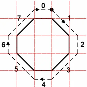
Figure 1. The directions and associated numbers for 8-directional chain codes.
Figure 2 Chain code for an octagon - starting from the dot, the chain code is 12345670
Each direction is represented by a number in the range [0-7]. The chain code traces the boundary of the shape, representing the direction across each grid cell by the appropriate direction number as shown in Figure 1. We note that the higher the definition of the image, the more grid cells, the longer the chain code and hence the more accurate the chain code. By using our Advanced Uncertain Reasoning Architecture (AURA) [A95] to match the chain codes we are able to efficiently match chain codes of long lengths.
Johnson Counter codes (also known as switch-tail ring counter codes) are binary reflected cyclic codes. They are used in the electronics industry for controlling operations in digital systems [M02]. The number of bits in the code can vary arbitrarily. Johnson Counter codes assign a code where the Hamming distance between two adjacent codes in a contiguous list is 1 and the Hamming distance increases monotonically as the distance between the number codes increases as shown in Table 1. The cyclic code effectively “wraps around” so the Hamming distance between 0 and 7 in a 4-bit code is also 1. This is particularly relevant for chain codes which are also cyclic. The 8-directional numbers of the chain code correlate to the same 8 decimal numbers of the Johnson code which in turn map to the 4-bit Johnson Counter code as shown in Table 1. For both the chain code directions and the Johnson Counter code: 7 is most similar to 0 and 6 and 0 is most similar to 7 and 1.
Decimal 4-bit Johnson codes
0 0000
1 0001
2 0011
3 0111
4 1111
5 1110
6 1100
[image:4.595.96.228.68.194.2]7 1000
Table 1 List of 4-bit Johnson codes
In this paper, we describe a binary neural shape matcher that represents shapes using a fusion of chain codes and Johnson Counter codes to allow distance-based matching. The fusion produces binary vectors which are integrated with a binary Random Access memory-based (RAM-based) neural network (AURA) to allow rapid, efficient and accurate indexing and matching of shapes in shape databases.
2 RAM-based Neural Networks
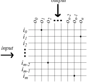
RAM-based networks were first developed by Bledsoe & Browning [BB59] and Aleksander & Albrow [AA68] for pattern recognition and led to the WISARD pattern recognition machine [ATB84]. RAMs are founded on the twin principles of matrices (usually called Correlation Matrix Memories (CMMs)) and n-tupling. Each matrix accepts m inputs as a vector or tuple addressing m rows and
n outputs as a vector addressing n columns of the matrix. During the training phase, the matrix weights Mlk are incremented if both the input row Ijl and output column Ojk
are set. Therefore, training is a single epoch process with one training step for each input-output association preserving the high speed. During recall, the presentation of vector Ij elicits the recall of vector Oj as vector Ij contains all
of the addressing information necessary to access and retrieve vector Oj. This training and recall makes RAMs
computationally simple and transparent with well-understood properties. RAMs are also able to partially match records during retrieval. Therefore, they can rapidly match records that are close to the input but do not match exactly.
2.1 AURA
The AURA provides a range of classes and methods for rapid partial matching of large data sets [A95]. AURA may be implemented using a C++ software library or using proprietary hardware coupled with a dedicated embedded C++ library [WFMA05]. AURA has been used in an information retrieval system [H01], high-speed rule matching systems [AKL95], 3-D structure matching [TA00] and trademark searching [AA98]. AURA software techniques have demonstrated superior performance with respect to speed compared to conventional data indexing approaches [HA01] such as hashing and inverted file lists which may be used for indexing. AURA software trains 20 times faster than an inverted file list and 16 times faster than a hashing algorithm. It is up to 24 times faster than the inverted file list for recall and up to 14 times faster than the hashing algorithm.
[image:4.595.92.234.269.411.2]distance-BICS 2006 – Brain Inspired Cognitive Systems Regular Paper
based binary vectors for training and recall make AURA ideal to use as the basis of an efficient implementation. A more formal definition of AURA, its components and methods now follows.
2.1.1 Training
Correlation Matrix Memories (CMMs) are the building blocks for AURA systems. AURA uses binary input I and output O
vectors to train records in to the CMM as in Equation 1 and Figure 3. Equation 1 OR logical is where all
∨
∨
×= j Ij OTj
CMM
Training is a single epoch process with one training step for each input-output association (each Ij x OTj in .
Equation 1) which equates to one step for each chain code Ij
which is associated with a unique identifier vector Oj with a
single bit set. The first bit is set for the first chain code to store; the second bit is set for the second chain code to store and so on.
Figure 3 Showing a CMM with input vector i and output vector o. Four matrix locations are set following training i0o0, i2on-2, im-1o0 and imon.
For the methodology described in this paper, we:
• Train the binary distance-based chain codes and their identifier vectors into the CMM allowing them to be matched.
• Match unseen binary chain codes using the trained CMM.
2.1.2
Input Vectors
Lu [L97] introduced procedures for normalising chain codes to ensure invariance to rotation and scaling. He proposes orienting shapes along the principal (major) axis of the shape. The minor axis lies perpendicular to this major axis. This forms a superimposed rectangle which may be subdivided into a grid of cells. To ensure scale normalisation we fix the perimeter-size of this grid so that it is equal for all shapes, for example a 4x4, 3x5, 2x6 or 1x7 grids all have equivalent perimeter length of 16. We thus superimpose the most appropriate of these onto the shape. If we fix the starting point to the top right cell then we have normalised for rotation and scale.
We further enhance Lu’s normalisation procedures to ensure that all stored and query chain codes are equivalent length. We propose counting diagonals twice. With an 8-directional chain code there are 3 routes from point (1,1) to point (2,2). They are: east then north (2 steps and thus 2 codes in a chain); north then east (2 steps and thus 2 codes in a chain); or, north-east which is 1 step and only 1 code in a chain so by ensuring that the diagonal counts twice all routes are 2 steps and 2 codes. The new chain code (with double diagonals) for Figure 2 is given in Figure 4.
In this paper, we assume that the chain codes have been normalised using Lu’s recommendations and our double diagonal augmentation.
AURA requires binary input vectors for training and storage. Thus, we convert the numeric chain code to a binary Johnson code equivalent. If we take the chain code for Figure 2 then we must convert each number in turn to a Johnson code as in Figure 4.
Figure 4 Chain code and its Johnson Counter code representation
We concatenate all Johnson codes together to form I. We then take I and logically negate all vector elements to form
Iˆ.
Figure 5 Chain code and its logically inverted Johnson Counter code representation
By concatenating I and Iˆ we produce I’ the distance-based binary chain code (the input vector for the CMM training) as in Equation 2.
Equation 2
I'
=
I
⊕
Iˆ
During recall, matching the first half (I) of I’ will count the number of matching 1s between the query and stored vectors and matching the second half (Iˆ) will count the number of matching 0s between the query and stored vectors. We note that exactly 50% of the elements in I’ will be set (active) using this approach. Each Johnson code element in I is inverted in Iˆ so each element will appear twice in I’ as both a 0 (inactive) and a 1 (active) thus 50% of the elements are active. Figure 6 shows a trained CMM where the rows are Johnson code bits and each column represents a distance-based binary chain code I’j (image shape) stored for
matching.
2.1.3
Chain Code Matching (Recall)
To retrieve the matching stored chain codes for a particular query chain code, AURA effectively calculates the dot product of the input vector Ik and the CMM, computing a
[image:5.595.43.187.327.461.2]Equation 3
O
=
I
k•
CMM
Tk
[image:6.595.68.207.93.452.2]Figure 6 Diagram showing a subsection of the CMM recall for a best match. Each column in the CMM (four rightmost columns) is a stored binary chain code representing the shapes (A, B, C & D) shown in Figure 7. The leftmost column is the input vector representing the chain code of the octagon from Figure 2 and represents a
concatenation of Q andQˆ. AURA multiplies the input vector by the values in the CMM matrix columns, using the dot product and sums each column to produce the summed output vector O.
To find the best matches for a particular chain code we initially create an input vector Q as per the training input vector so the chain code 112334556770 would be mapped to a Johnson code input vector as in Figure 4. This chain code is 12 elements long and each element comprises 4 binary bits so the a perfect match would score 48.
We then logically negate this binary input vector to produce
Qˆ and append Qˆ to the end of the query vector Q. The resultant query input vector is thus:
Equation 4 Q'=Q⊕Qˆ.
We note that 50% of the elements in Q’ will be set so 50% of the CMM rows will be activated during recall thus recall is
predictive and constant for equivalent length chain codes (ignoring extraneous factors).
We input this to the CMM to elicit a summed output vector,
Oas per Equation 3, which effectively counts the number of matching 1s AND 0s between the input and each, stored chain code. As we have input the binary chain code and negated binary chain code we have effectively counted the number of matching 1s and 0s
The proposed method then calculates the score for each stored chain code using the summed output vectors (counting matching 1s and 0s, O).
For each stored chain code (each position j in the summed vectors) we calculate the score as:
Equation 5
Score
=OjThis is essentially the negated XOR (~XOR or inverse Hamming Distance) of the input with each stored binary chain code and counts the number of matching 1s AND 0s between the query and the stored code. This score represents the degree of match and will decrease monotonically as the similarity between the input and a stored code decreases. For best matching, we store the index (position j in the summed output vectors) of the chain code(s) with the highest score.
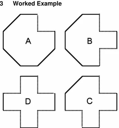
3 Worked Example
Figure 7 Showing the four shapes represented by the chain codes stored in the CMM in Figure 6. The dotted lines indicate where each of the shapes differs from the query shape in Figure 2
[image:6.595.316.512.393.604.2]BICS 2006 – Brain Inspired Cognitive Systems Regular Paper
shapes A, B, C & D respectively; the binary codes for the query Q and the four stored shapes A, B, C & D respectively and Figure 9 shows the inverted binary codes for the query Qˆ
and the four stored shapes
A
ˆ
,
B
ˆ
,
C
ˆ
&
D
ˆ
respectively.Figure 8 Showing the chain code & binary code for the query shape represented by Figure 2 (top) and the chain codes & binary codes for the four shapes in Figure 7 (A, B, C & D from top to bottom). The digits in red indicate where each of the shapes (A, B, C & D from top to bottom) differs from Figure 2.
Figure 9 Showing the inverted binary code Qˆ for the query shape represented by Figure 2 (top) and the binary
codes (
A
ˆ
,
B
ˆ
,
C
ˆ
&
D
ˆ
from top to bottom) for the four shapes in Figure 7. The digits in red indicate where each of the shapes (A, B, C & D from top to bottom) differs from Figure 2.For the standard technique the scores for the four shapes A, B, C & D in Figure 6 - Figure 8 compared to the query shape are:
Score_A = 2 Score_B = 4 Score_C = 6 Score_D = 8
For the standard technique, the lowest score indicates the best match so A is the best match (as we would expect) and differs to the query by 2 (i.e. two 1/8 directions are different between the query and shape A). The differences are in the first two elements of the chain code where the query begins “11” and A begins “20” giving a cumulative difference of 2. Shape D is least similar to the query as it scores highest and thus differs in
eight 1/8 directions. It differs from the query in elements 1, 2, 4, 5, 7, 8, 10 & 11.
For the AURA approach, the scores for the 4 stored chain codes in Figure 6 - Figure 8 compared to the query shape are:
Score_A = 46/48 Score_B = 44/48 Score_C = 42/48 Score_D = 40/48
For the AURA technique, we are counting matching 1s in Q compared to A, B, C & D and matching 1s in Qˆ compared
to
A
ˆ
,
B
ˆ
,
C
ˆ
&
D
ˆ
. In contrast to the standard approach, the shape with the highest score is the best match to the query. For the standard technique we are counting differences (hence the lowest score represents the best match). The standard score is the maximum score permissible in AURA minus the actual score, i.e. for shape A, the maximum permissible score is 48 and the actual score is 46 so the standard score is 2 (as seen above). Shape A is the most similar to the query as it scores highest. Shape D is least similar to the query as it scores lowest. Shape A differs from the query by 2 which indicates that it differs in two 1/8 directions – those shown by dotted lines in Figure 7. Shape D differs in eight 1/8 directions – those shown by dotted lines in Figure 7.If we ~XOR the query vector with the best matching vector(s), where the resultant vector is 0 is where the stored vector differs from the query. This facility is useful for pinpointing shape variations.
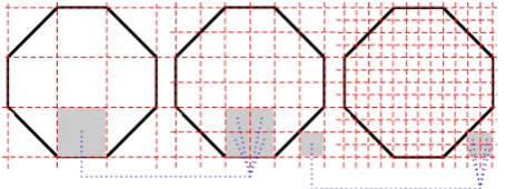
4 Multi-Resolution Chain Coding
We can introduce multi-resolution chain codes. By using a point-region quad-tree1 (PRQ) reduction, we can produce a
boundary at various levels of resolution. Each different resolution requires a separate CMM for training and matching due to the variation in length of the vectors.
The lowest resolution chain coding (grid with fewest cells) may be used for a quick and dirty match to perhaps narrow the search space in an extremely large database of shapes. As the resolution increases down the PRQ (as the number of cells in the grid increases monotonically by a factor of 4) then the size and precision of the chain code increases by a factor of 2 (the perimeter is twice as long) so the number of rows in the CMM would increase by a factor of 2 for each layer in the PRQ. The matching will obviously be slower due to the increase in size of the vectors but this will be offset by the increase in precision.
1 A point region quad-tree is a quad-tree where each node must
Figure 10 Figure showing a PRQ reduction (from left to right) of the grid in Figure 2. There are 36 cells in the centre shape compared to 9 cells in the leftmost shape. The chain code for the centre shape will be twice as long (the perimeter is now twice as long) as the leftmost shape. The rightmost shape has 144 cells and the perimeter is 4 times as long as the leftmost shape and twice as long as the centre shape.
5 Proposed Method
If the database is relatively small, train a single CMM with chain codes at high precision (the largest chain code length permissible within the storage available). This may then be used for matching query shapes.
If the database is very large then we propose training the shapes into a low precision CMM which will minimise the storage requirements. If we query this low precision CMM to retrieve a set of candidate shapes then these candidates may be trained into a subsequent higher precision CMM. Again, querying this higher precision CMM will retrieve a set of better matches. This cycle of retrieving matches, increasing the precision, training a higher precision CMM and then querying can be repeated until the database of shapes has been reduced to the requisite number of matches.
6 Conclusion
In this paper we have introduced a binary neural shape matcher. The AURA neural architecture, which underpins the classifier, has demonstrated superior training and recall speed compared to conventional indexing approaches such as hashing or inverted file lists. AURA trains 20 times faster than an inverted file list and 16 times faster than a hashing algorithm. It is up to 24 times faster than the inverted file list for recall and up to 14 times faster than the hashing algorithm. In this paper, we described the implementation details of the technique. Our next step is to evaluate the AURA decision table for speed and memory usage against a conventional chain code matcher.
We feel the technique is flexible and easily extended to other domains/systems where distance-based numeric code matching is required.
7 References
[AA68]
Aleksander, I., & Albrow, R.C. Pattern recognition with Adaptive Logic Elements. IEE Conference on Pattern Recognition, pp 68-74, 1968.
[ATB84]
Aleksander, I., Thomas, W.V., & Bowden, P.A.
Wisard: A radical step forward in image recognition. Sensor Review, pp 120-124, 1984.
[AA98]
Alwis, S., & Austin, J. A Novel Architecture for Trademark Image Retrieval Systems. In,
Electronic Workshops in Computing, 1998.
[A95]
Austin, J. Distributed Associative Memories for High Speed Symbolic Reasoning. In, IJCAI Working Notes of Workshop on Connectionist-Symbolic Integration: From Unified to Hybrid Approaches, pp 87-93, 1995.
[A98]
Austin, J. RAM-based Neural Networks, Progress in Neural Processing 9, Singapore: World Scientific Pub. Co., 1998.
[AKL95]
Austin, J., Kennedy, J., & Lees, K. A Neural Architecture for Fast Rule Matching. In, Artificial Neural Networks and Expert Systems Conference (ANNES’95), Dunedin, New Zealand, 1995.
[BB59]
[image:8.595.35.263.58.143.2]Bledsoe, W.W., & Browning, I. Pattern recognition and Reading by Machine. In, Proceedings of Eastern Joint Computer Conference, pp 225-231, 1959.
[BSBKF99] Biederman, I., Subramaniam, S., Bar, M., Kalocsai, P, &
Fiser, J. Subordinate-Level Object Classification Re-examined. Psychological Research, 62:131-153, 1999.
[H01]
Hodge, V., Integrating Information Retrieval & Neural Networks, PhD Thesis, Department of Computer Science, The University of York, 2001.
[HA01]
Hodge, V. & Austin, J. An Evaluation of Standard Retrieval Algorithms and a Binary Neural Approach. Neural Networks 14(3), pp. 287-303, Elsevier, 2001.
[L97]
Lu, G. An approach to image retrieval based on shape. Journal of Information Science, 23(2): pp. 119-127, 1997.
[M02]
Mano, M. Digital design. 3rd Edition. Prentice-Hall, NJ, 2002. ISBN: 0130621218.
[MGR02]
Mojsilovic, A., Gomes, J. and Rogowitz, B. ISee: Perceptual features for image library navigation, Proc. 2002 SPIE Human Vision and Electronic Imaging.
[TA00]
Turner, A., & Austin, J. Performance Evaluation of a fast Chemical Structure Matching Method using Distributed Neural Relaxation. In, 4th International conference on Knowledge Based Intelligent
Engineering Systems, 2000.
[WFMA05]
Weeks, M., Freeman, M., Moulds A. & Austin, J.
Developing Hardware-Based Applications Using PRESENCE-2 . Perspectives in Pervasive
Computing 2005, 25th October 2005 at the IEE, Savoy Place, London
8 CVs of authors:
Prof. Jim Austin: has the Chair of Neural Computation in the Department of Computer Science, University of York, where he is the leader of the Advanced Computer Architecture Group. He has extensive expertise in neural networks as well as computer architecture and vision. Jim Austin has published extensively in this field, including a book on RAM based neural networks.
BICS 2006 – Brain Inspired Cognitive Systems Regular Paper
content-based image retrieval, the detection of anomalous records in large data sets, data classification, feature selection and the integration of neural networks and information retrieval.