© 2016, IRJET ISO 9001:2008 Certified Journal Page 2642
Design and Development of a model to verify enhancement in heat
transfer rate using jet impingment
Subrata Mukhopadhyay
1, Mayur Waghchoure
2, Tushar Shinde
3, Prakalp Shah
4,A.S. Joglekar
51,2,3,4
Student, Dept. of Mechanical Engineering, Smt. Kashibai Navale College Of Engineering, SPPU, Pune, India
5Assistant Professor, Dept. of Mechanical Engineering, Smt. Kashibai Navale College Of Engineering, SPPU, Pune,
India
---***---Abstract -
In application like nuclear reactor and turbine blade very large amount of heat flux is generated and to carry out huge heat flux to heat sink due to inability of other mode of heat transfer, jet impingement is used in current investigation through academic perspective. We have developed design procedure for jet impingement and set specification of various component of test rig for jet impingement.We also investigate relation between velocity at nozzle exit and velocity over copper plate on the basis of experimental data to predict proportional constant relating them. We have validated enhancement of heat transfer rate by various fluids and conclude superiority of nanofluid with additional power loss due to viscosity.
We also investigate effect of flow rate and nozzle diameter over heat transfer coefficient and proportional constant with the help of various graphs and result tables.
Key Words
:
nanofluid , Heat Transfer, Ethylene Glycol, Jet Impingement, Jump Profile, Microprocessors.
1. INTRODUCTION
Jet impingement is one of method of increasing heat transfer at tremendous rate. Jet impingement can be either air-powered or use some form of liquid, typically water jet. It is a process in which a jet of fluid coming out of a nozzle at very high velocity impinges on the surface from which heat has to be removed. As these high jet velocity is normal to the plane, it will not get affected by friction of surface plate to the extent as the velocity is affected in forced convection with horizontal movement of fluid, due to less velocity, heat transfer rate is also less in forced convection. Therefore jet impingement is more preferred over forced convection
technique. Due to high relative velocity heat transfer rate will be maximum; as heat transfer coefficient is maximum By Newton law of cooling Q=hA(∆T), as A and ∆T will remain constant, heat transfer rate will increase due to increase in heat transfer coefficient only.
There are three common jet configurations: free surface jet that uses dense liquid in a medium which is less dense such as air; submerged jet which allows the fluid to impinge in the same fluid medium; and the confined submerged jet. Jet impingement technique is one of the passive methods of convective heat transfer. The convective heat transfer in this type of cooling is based on the jet impingement velocity, adjacent jet distance to jet diameter (S/d), number of jets (n), distance between two rows of jet, jet diameter (d), target distance to jet diameter (z/d), Reynolds number (Re), Prandtl number (Pr) and physical geometry of heat sink.
2. EXPERIMENTAL SETUP
© 2016, IRJET ISO 9001:2008 Certified Journal Page 2643 respectively. The ethylene glycol (water or nanofluid) jet
emerges from nozzle (1) and impinges on a circular copper plate disc(8) of 200mm diameter. The falling liquid is collected in a collecting tray (6). The circular plate is heated using an electric heater (7) of 550 watt as shown in the figure. The power of the heaters is controlled using a dimmerstat (10). The voltage across the heater, the current through the heater, and the electric power are measured by a power meter (10). The temperatures of the hot circular plate are measured using platinum thermocouples (11) which is made up of platinum material having range up to 600˚C and temperature readings are noted for further analysis using 6-point temperature indicator(9) (up to range of 1200˚C) which are mounted in radial direction over a copper plate symmetric about centre of a copper plate disc each 3.33cm apart .
Two nozzles of different diameters are used in the current investigation as 6 and 8mm. The height of the nozzle above the hot Plate is maintained at three different heights during this investigation. The circular plate used in the investigation is copper in order to have better heat transfer rate. A plaster of paris and glass wool insulation are used to enclose the circular heater plate as shown in Figure. The thickness of the copper plate is 1 mm. The electric heaters used are round plate heater as heating elements. The heater is placed inside a cylindrical sheet of metal filled with plaster of paris as shown in Figure. Mica can be used to keep the heater and copper plate separate from each other to avoid physical contact between them for avoiding electrical shocks. The thermocouples are impeded in 3 mm diameter holes in the copper plate using adhesives.
3. METHODOLOGY
3.1 For transient cooling
[1] Measure the atmospheric temperature with the help of thermometer.
[2] Measure the temperature of fluid with the help of thermometer.
[3] Switch on the temperature indicator.
[4] Switch on the heater.
[5] Measure the time for heating from 36˚C to 60˚C . [6] Measure the voltage and current from control panel. [7] Switch on the motor, Adjust the flow with the help of flow control valve by pointing the jet away from copper plate in the tank.
[8] Point the jet on the centre of copper plate for 11 seconds as soon as 60˚C temperature of copper plate is achieved. [9] Switch off the motor after 11 seconds.
[10] Note down the temperature T1,T2,T3,T4,T5 and T6 as
steady state is achieved.(approximately by 30 seconds). [11] Repeat the same experiment for following
[1] Flow rate: 400,500 and 600lph [2] Nozzle diameter: 6mm and 8mm [3] Various z/d ratios
[4] for various fluids- water, ethylene glycol, 0.1% nanofluid and 0.3% nanofluid
3.2 Relation between v
jetand v
over copper plate Q nozzle exit = Q over copper plate at (D1=12cm)D1=Diameter of circle at which height (h) is
measured=120mm H=height of fluid flow d=nozzle diameter
4. OBSERVATIONS
Table No.-1 Relation between vjet and v over copper plate
Flow
rate D
1(mm) Height of
flow over copper plate(mm)
for 6mm nozzle dia.
Height of flow over copper plate(mm) for 8mm nozzle dia.
400 120 4.5 7
500 120 3.5 5.5
© 2016, IRJET ISO 9001:2008 Certified Journal Page 2644
Table No. 2- Observation for water jet impingement
6mm nozzle diameter
z/d 6.2 4
Lph
Temp.(°C) 400 500 600 400 500 600
1 44 40 42 39 39 39
2 44 40 41 40 39 40
3 45 39 40 39 39 39
4 46 39 39 40 38 39
5 45 40 40 40 39 40
6 54 45 46 46 44 45
7 29 29 29 29 29 29
Table No. 3- Observation for water jet impingement
8mm nozzle diameter
z/d 6.2 4
Lph
Temp.(°C) 400 500 600 400 500 600
1 41 39 37 39 37 39
2 41 40 39 39 38 37
3 40 39 39 40 39 38
4 38 39 40 37 37 36
5 42 40 42 39 39 40
6 52 48 48 44 46 50
7 31 31 31 32 32 32
5. SAMPLE CALCULATIONS
Given data: d=6mm (nozzle diameter) Time of cooling, t=11 seconds
K copper=386 W/m K
ρ=8954 Kg/m3
D=200mm
Cp=383 J/KgK
Thickness of copper plate (l) =1mm Q=400 lph
Ti =60˚C
Z/d=6.2
Tavg = T1+T2 +T3 +T4+T5+T6 /6
Tavg =46.33˚C
Characteristic length(v/A)=length of copper plate=1mm
h=181.3 w/m2 k
6. RESULTS AND DISCUSSION
Table No.4- Relation between vjet and vover copper plate
For 6mm
Flow rate K Flow rate×K
400 60 24000
500 46.66 23333.5
600 40 24000
Table No.5- Relation between vjet and vover copper plate
For 8mm
Flow rate K Flow rate×K
400 56.25 22500
500 41.25 20625
600 33.75 20250
© 2016, IRJET ISO 9001:2008 Certified Journal Page 2645
Table No. 6- Heat transfer coefficient for water jet impingement
z/d ratio Flow rate hexp for 6mm
nozzle hexp nozzle for 8mm
6.2
400 181.30 342.72
500 309.16 337.28
600 287.43 337.28
5
400 323.02 302.22
500 352.73 313.77
600 337.52 353.56
4
400 304.85 376
500 332.81 388.91
[image:4.595.307.563.140.276.2]600 313.8 364
Table No. 7- htheo for all fluid
nozzle
diameter z/d flow rate hfor theo water
htheo for
ethylene glycol
htheo for
0.1% conc.
6mm 6.2 400 235.08 500 300.94 77.57 98.69 1832.94 2331.84
600 356.27 116.66 2756.44
8mm 4.625 400 183.95 500 240.06 60.08 78.76 1419.78 1860.92
600 290.89 95.25 2250.62
Table No.-8 Reynold number for all fluids
nozzle
diameter z/d flow rate Re for water ethylene Re for glycol
Re for 0.1% conc.
6mm 6.2 400 3876.73 500 6274.35 308.22 498.84 272.69 441.34
600 8789.2 697.05 616.7
8mm 4.625 400 2343.27 500 3990.6 184.93 317.7 163.61 281.08
600 5859.47 464.7 411.14
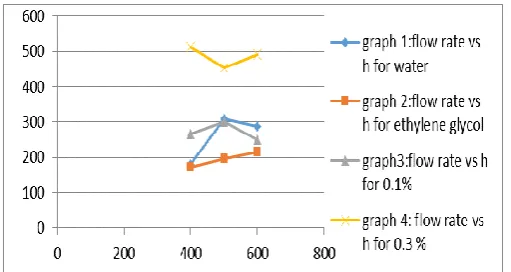
Graph No.1- Graph of flow rate vs hexp for nozzle diameter 6mm and z/d ratio 6.2
Graph No. 2- Graph of flow rate vs hexp for nozzle diameter 8mm and z/d ratio 6.2
Graph No 3- Graph of flow rate vs K for nozzle diameter 6, 8mm and z/d ratio 6.2&4.625 resp.
[image:4.595.310.563.317.474.2]© 2016, IRJET ISO 9001:2008 Certified Journal Page 2646
7. CONCLUSION
For laminar flow, it is concluded that jet impingement is superior to all modes of convective heat transfer and also heat transfer coefficient for jet impingement is maximum for nanofluid and increases with nanoparticle concentration which is followed by water and ethylene glycol. Nusselt number, reynold number and heat transfer coefficient varies directly with flow rate for same nozzle diameter, z/d ratio and varies inversely to nozzle diameter for same flow rate. Heat transfer coefficient found to be varies inversely with z/d ratio for z/d ratio less than 5and directly with z/d ratio for z/d ratio greater than 5, for same nozzle diameter. Also found to be directly proportional to z/d ratio for nozzle diameter varies keeping z constant. Product of proportional constant k and flow rate in lph is approximately constant for same nozzle diameter and varies inversely with nozzle diameter for same flow rate. Theoretical relation for turbulent flow obtained is as follows,
h = .0366*(ρ*V*Lc/µ).8 (µ*Cp/k).33(k/Lc)
From above relation, it is conclude that heat transfer rate can be increased by significant increase in density, velocity of fluid flow and decrease in characteristic length of fluid flow, boundary layer thickness, which can be achieved by jet impingement over normal forced convection and conduction and varies as per change in nozzle diameter and z/d ratio. For various fluids to give better performance for jet impingement, it should have high thermal conductivity,
specific heat capacity, thermal diffusivity and less prandtl number.
8. FUTURE SCOPE
Current study is done on plate of size 20cm, but the study can be further extended by increasing the plate size. Current study consist of temp. of 6 point, but for better results point of temperature measurement can be increased. Various concentration can be studied, rather than concentration that are used in the current investigation. The present works can be extended for the computational analysis for future study. Various Nanofluid can be used for the experimentation purpose. Ex. Al2O3 Circular plate of different diameter can be
used for experimentation.
9. ACKNOWLEDGEMENT
We would like to express our gratitude to all the people who helped us put this paper into Publication. We would like to thank Prof. A.S. Joglekar for guiding us .We also would like to thank Dr. A.P. Pandhare for constantly encouraging us during our project work.
We would also like to acknowledge the efforts of our parents for constantly supporting us.
10. REFERENCES
[1] S.U.S Choi,Enhancing thermal conductivity of fluids with nanoparticles,Developments and applications of Non Newtonian Flows,FED-vol 231/MD-vol. 66,1995,pp99-105
[2] B Sagot,G Antonini,A Christgen,F Buron, Jet impingement heat transfer on a flat plate at a constant wall temperature ,International Journal of Themal Sciences 47(2008) 1610-1619
[3] Xiang-Qi Wang , Arun S majumdar Heat transfer characteristics of nanofluids a review International Journal of thermal sciences 46(2007) 1-19
© 2016, IRJET ISO 9001:2008 Certified Journal Page 2647 Journal of heat transfer 127(2005) 760-769
[5] Brain p Whelan A j robinson Nozzle geometry effects in liquid jet array impingement applied Thermal Engineering 29(2009) 2211-2221
[6] BC pak Y cho Hydrodynamic and heat transfer study of dispersed fluids with submicron metallic oxide particle Experimental Heat transfer