University of Southern Queensland
Faculty of Engineering and Surveying
Building a Two Wheeled Balancing Robot
A dissertation submitted by
Mr Peter Miller
In fulfilment of the requirements of
Courses ENG4111 and 4112 Research Project
towards the degree of
Bachelor of Engineering (Electrical and Electronic)
Abstract
Two wheeled balancing robots are an area of research that may well provide the future locomotion for everyday robots. The unique stability control that is required to keep the robot upright differentiates it from traditional forms of robotics. The inverted pendulum principle provides the mathematical modelling of the naturally unstable system. This is then utilised to develop and implement a suitable stability control system that is responsive, timely and successful in achieving this objective.
Completing the design and development phase of the robot requires careful consideration of all aspects including operating conditions, materials, hardware, sensors and software. This process provides the ongoing opportunity of implementing continued improvements to its perceived operation whilst also ensuring that obvious problems and potential faults are removed before construction.
The construction phase entails the manufacture and assembly of the robots circuits, hardware and chassis with the software and programming aspects then implemented. The later concludes the robots production where the final maintenance considerations can be determined. These are essential for ensuring the robots continued serviceability.
Certification
I certify that the ideas, designs and experimental work, results, analyses and conclusions set out in this dissertation are entirely my own effort, except where otherwise indicated and acknowledged.
I further certify that the work is original and has not been previously submitted for assessment in any other course or institution, except where specifically stated.
Peter Miller
Student Number: 0050031502
Signature
Acknowledgements
I would like to extend my appreciation and love to my family for all their continuing support, care and consideration. For my loving wife who has given me every opportunity to succeed, for my fantastic son who has always shared the interest, and my beautiful daughter who always knew I could do it, thank you for sharing the journey with me. And, thank you to my mum and dad, Audrey and Phil, for all the support and guidance over the years.
Table of Contents
Abstract i Acknowledgements iv
List of Figures viii
List of Tables x
List of Appendices xi
List of References xii
Chapter 1 – Introduction
1.1 Two Wheeled Balancing Robots 1
1.2 Inverted Pendulum Theory 2
1.3 Autonomous Stability 6
1.4 Project Objectives and Timeline 7
1.5 Methodology 8
1.6 Risk Assessment 9
1.7 Conclusion 11
Chapter 2 – Literature Review
2.1 Introduction 12
2.2 Existing Two Wheeled Balancing Robots 13 2.3 Purpose and Benefits of Two Wheeled Robots 16 2.4 Modes of Operation and Control 18 2.5 Implications and Ethics of Technology 18
2.6 Conclusion 19
Chapter 3 – Design and Development
3.1 Introduction 20
3.2 Control System 20
3.3 Software and Programming Concept 26
3.4 Design Considerations 31
3.4.1 Operating Environments 31
3.4.2 Materials, Size and Weight 32
3.4.3 Wheels 33
3.4.4 Motors 34
3.4.6 Microcontroller 41
3.4.7 Components / Circuits 43
3.4.8 Stability Control Requirements 44
3.4.9 Power Source 46
3.4.10 Locomotion Control 49
3.4.11 Communications 50
3.4.12 System Integration 50
3.4.13 Safety Features 52
3.4.14 EMR / EMI 53
3.5 Design Concept “Oshy” 54
3.6 Resources 56
3.7 Conclusion 57
Chapter 4 – Manufacture and Assembly
4.1 Introduction 58
4.2 Printed Circuit Boards 58
4.3 Wheel Base 61
4.4 Power Source 62
4.5 Interaction System and Upper Layer 62
4.6 Software and Programming 63
4.6.1 Simulation 63
4.6.2 Microchip Program 64
4.7 System Integration and Overview 64 4.8 Future Maintenance Considerations 65
4.9 Conclusion 66
Chapter 5 – Data Analysis
5.1 Introduction 67
5.2 Calibration and Tuning 67
5.3 Stability Analysis 68
5.4 Locomotion Analysis 68
5.5 System Performance Overall 69
Chapter 6 – Conclusion and Recommendations
6.1 Introduction 70
6.2 Discussion 70
6.2.1 Difficulties Experienced 70
6.2.2 Design Advantages and Disadvantages 71 6.2.3 System Performance and Results 71 6.2.4 Results versus Expectations 72
6.3 Conclusion 72
6.4 Recommendations 72
6.4.1 Improvements and Alterations 72 6.4.2 Additional Features and Capabilities 72 6.4.3 Future Areas of Investigation 73
List of Figures
1.1 Views of the two wheeled balancing robot 2 1.2 Displacement, velocity and acceleration parameters 4
1.3 Inverted pendulum parameters 4
1.4 Wheel parameters 5
1.5 Dissertation completion timeline 8
2.1 Segway HTi series two wheeled transport 14
2.2 Emiew 2 by Hitachi 15
2.3 nBot by David Anderson 15
3.1 Input 1 - Angle membership function 22 3.2 Input 2 - Angular velocity membership function 23 3.3 Input 3 - Displacement membership function 23 3.4 Input 4 - Velocity membership function 23 3.5 Output – Motor output membership function 24 3.6 Angle and angular velocity rule set surface plot 26 3.7 Displacement and velocity rule set surface plot 26
3.8 Microcontroller structure chart 27
3.9 Microcontroller main program flowchart 28 3.10 Sensors and locomotion desired sub-routine flowcharts 29 3.11 Fuzzy control and locomotion response sub-routine flowcharts 30
3.12 Control system functionality 30
3.13 Differential drive motion 35
3.14 L298 motor driver PCB 37
3.15 Sharp GP2D12 sensor (Sharp) 40
3.16 Microcontroller circuit 43
3.17 Maximum tilt angle variables 45
3.18 Voltage monitoring circuit 47
3.19 12V distribution circuit 49
3.20 Low voltage distribution circuit 49
4.1 Microcontroller circuit PCB 59
4.2 12V distribution PCB 60
4.3 5V and 3.3V distribution PCB 60
4.4 Gyroscope and accelerometer PCBs respectively 61
4.5 Wheel base layers 61
List of Tables
1.1 Risk Assessment of Research Project 10
List of Appendices
A Project Specification 77
B Matlab Programming 78
List of References
Anderson, DP, 2007, nBot Balancing Robot, viewed 20th March 2008, <http://www.geology.smu.edu/~dpa-www/robo/nbot/>
Bush, L 2001, Fuzzy Logic Controller for the Inverted Pendulum Problem.
Deepa, S, Sivanandam S & Sumathi, S 2007, Introduction to Fuzzy Logic using MATLAB, Springer, New York.
Florian, RV, 2007, Correct equations for the dynamics of the cart-pole system, Center for Cognitive and Neural Studies, viewed 15th May 2008,
<http://www.coneural.org/florian/papers/05_cart_pole.pdf>
Larson, T, 2008, Balancing Robot Project - Bender, viewed 20th March 2008, <http://www.tedlarson.com/robots/balancingbot.htm>
McComb, G & Predko, M 2006, Robot Builders Bonanza, McGraw-Hill, Sydney. Segway Inc, 2008, Simply moving, viewed 20th March 2008,
<http://www.segway.com/>
Chapter 1
Introduction
Robotics has always been played an integral part of the human psyche. The dream of creating a machine that replicates human thought and physical characteristics extends throughout the existence of mankind. Developments in technology over the past fifty years have established the foundations of making these dreams come true. Robotics is now achievable through the miniaturisation of the microprocessors which performs the processing and computations. New forms of sensor devices are being developed all the time further providing machines with the ability to identify the world around them in so many different ways.
Effective and efficient control system designs provide the robot with the ability to control itself and operate autonomously. Artificial intelligence (AI) is becoming a definite possibility with advancements in non-linear control systems such as neural networks and fuzzy controllers. Improved synthetics and materials allow for robust and cosmetically aesthetic designs to be implemented for the construction and visual aspects of the robot.
Two wheeled robots are one variation of robot that has become a standard topic of research and exploration for young engineers and robotic enthusiasts. They offer the opportunity to develop control systems that are capable of maintaining stability of an otherwise unstable system. This type of system is also known as an inverted pendulum. This research project aims to bring this, and many of the previously mention aspects of a robot together into the building of a two wheeled balancing robot with a non-linear, fuzzy controller.
This field of research is essential as robots offer an opportunity of improving the quality of life for every member of the human race. This will be achieved through the reduction of human exposure to hazardous conditions, dangerous environments and harmful chemicals and the provision of continual 24 Hr assistance and monitoring for people with medical conditions, etc. Robots will be employed in many applications within society including carers, assistants and security.
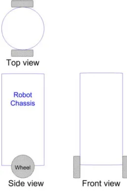
1.1 Two Wheeled Balancing Robots
This type of robot provides a challenging problem and has resulted in many useful and interesting designs being developed. One such two wheeled robot that has become a commercial success is the Segway by Segway Inc. The immediate impact has been within the personal transportation area where an alternative to cumbersome wheelchairs is now available. Segway proves a comfortable mobility opportunity for the elderly or people with disability thus improving there individual sense of independence at the same time. The theory used to maintain stability of these robots is based on the inverted pendulum theory which is covered in the following section 1.2.
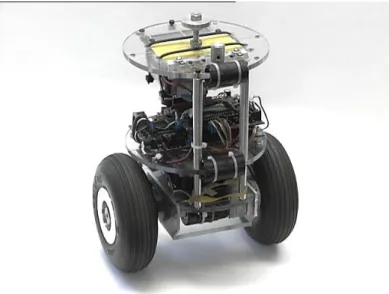
Figure 1.1 Views of the two wheeled balancing robot
1.2 Inverted Pendulum Theory
To develop a reliable and capable control system for a two wheeled balancing robot, an understanding of the parameters within the system is essential. Representation of these can be achieved through a mathematical model. Inverted pendulum theory is more traditionally known as Pole and Cart theory and although the two wheeled balancing robot does not directly compare to the Pole and Cart, the same principles are in effect. Within the system model, the cart equates to the wheels whilst the pole equates to the robot’s chassis.
Friction coefficients have been neglected in this project as the robot will be expected to transverse across numerous types of terrains and surfaces. If the coefficients were to be considered during the control systems design and implementation, then additional sensors, circuitry and power consumption would be required to derive these new values whilst in operation. The time, effort and resources required to create this capability far exceed any benefits that could be expected with there inclusion.
It is necessary to generalise the effects of the left and right wheels and incorporate them together under the combined term “wheels”. This simplifies the calculations as both wheels will work in unison to maintain stability. For determining specific torque (forces) requirements for each individual wheel, the wheels value can be halved for an approximate single wheel value. This approach is considered acceptable as the terrain and surface will vary between the wheels on certain terrains.
The aim of the inverted pendulum principle is to keep the wheels beneath the centre of the robot chassis’s mass. If the robot begins to tilt forward, then to maintain stability, the wheel will need to move forward to return beneath the chassis mass. If this is not maintained, the robot will simply fall over. The following system dynamics are associated with the mathematical problem.
System Dynamics
The following system dynamics are utilised within the mathematical problem of the two wheeled balancing robots stability control (inverted pendulum approach).
x Displacement (Horizontal) (m)
x Velocity (Horizontal) (ms-1)
x Acceleration (Horizontal) (ms-2)
Angular displacement (Vertical) (rad s) Angular velocity (Vertical) (rad s-1) Angular acceleration (Vertical) (rad s-2)
Mwh Mass of the wheels and drive shafts (Kg) Mrc Mass of the robot chassis (Kg)
Figure 1.2 Displacement, velocity and acceleration parameters
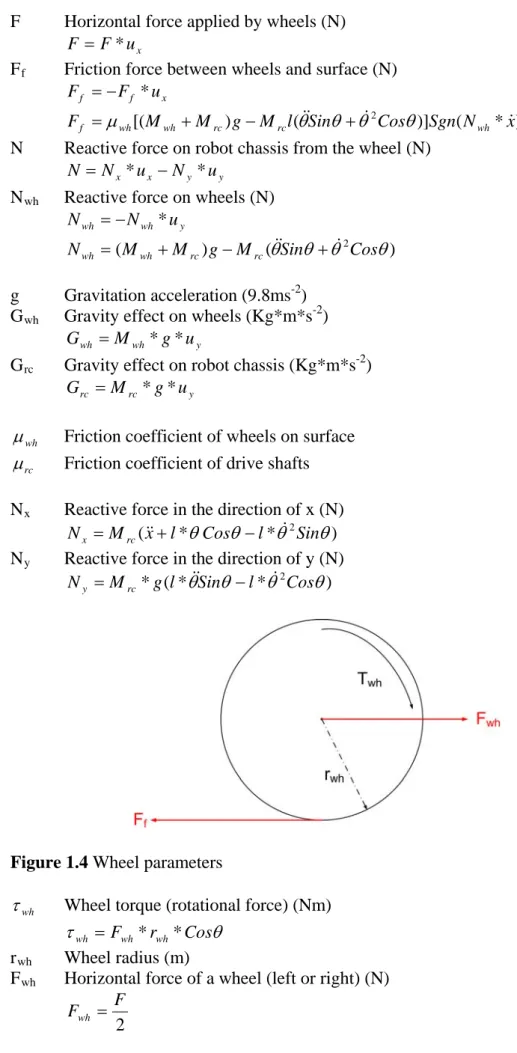
F Horizontal force applied by wheels (N)
x
u F F *
Ff Friction force between wheels and surface (N)
x f
f F u
F *
) * ( )] ( )
[(M M g M l Sin 2Cos Sgn N x Ff wh wh rc rc wh
N Reactive force on robot chassis from the wheel (N)
y y x
x u N u
N
N * *
Nwh Reactive force on wheels (N)
y wh
wh N u
N *
) (
)
( 2
Cos Sin M g M M
Nwh wh rc rc
g Gravitation acceleration (9.8ms-2) Gwh Gravity effect on wheels (Kg*m*s-2)
y wh
wh M g u
G * *
Grc Gravity effect on robot chassis (Kg*m*s-2)
y rc
rc M g u
G * *
wh
Friction coefficient of wheels on surface
rc
Friction coefficient of drive shafts
Nx Reactive force in the direction of x (N) ) *
*
(x l Cos l 2Sin M
Nx rc
Ny Reactive force in the direction of y (N) ) *
* (
*g l Sin l 2Cos M
Ny rc
Figure 1.4 Wheel parameters
wh
Wheel torque (rotational force) (Nm)
wh Fwh*rwh*Cos rwh Wheel radius (m)
Fwh Horizontal force of a wheel (left or right) (N)
The desired motor torque is estimated during the motor considerations within hapter 3. Motor torque is the force applied to the wheel before frictional and
echanical losses are subtracted. The resultant torque, also known as applied torque,
fer he importance of selecting the
displayed in the wheel torque quation. This indicates that a larger radius for the wheel would require a larger torque to be applied by the motor.
e view as 94% or 87% of the torque available is now required compared to the previous 100%.
C m
r
is e red to as wheel torque in these equations. T correct radius of wheel is evident from the effects e
The cosine function within the wheel torque equation details the advantage of tilting the robot chassis in the direction desired locomotion. If the robot was to begin moving forward and the tilt angle in that direction is increased, then the torque required to move the robot in that direction will be reduced. For example, when the angle of tilt is 0o, the cosine multiplier will be 1 equating to 100% of the torque. When the angle of tilt increases to 20o or even 30o, then the multiplier will equal 0.94 and 0.87 respectively. This could b
The following equations will provide a reliable and accurate model for developing and implementing a suitable non linear control system for the two wheeled balancing robot.
Angular acceleration
wh rc
rc M M l 3
wh rc
Cos M * 2 4 orizontal acceleration rc M M Sin l M F Cos Sin
g
2 * * *
rc wh rc M M Cos Sin l M F x 2 * Htability
Stability for the two wheeled balancing robot lies in its ability to maintain the robot chassis in an upright, equilibrium, position. Balancing a robot automatically without uman interaction is known as autonomous stability because it does this by self governance. The inverted pendulum theory provides the equations required to nd reactions that occur in the process. It is then necessary to e and efficient control system that is capable of responding to the eframe so that stability can be attained, and then
1.3 Autonomous S
h
ascertain motion, force a apply an effectiv
sensory inputs within a minimal tim maintained.
1.4 Pr
l system capable of maintaining tability of the robot. The resultant physical circuitry requirements were then
rt of the third goal.
project. These key oals/objectives are defined as follows:
. A non-linear control system will be designed and then simulated to ascertain
d including the necessary circuitry, sensors and circuit boards. Additional, the unit will be configured with an interface
ource requirements sourced. Manufacture and assembly will begin with the final outcome of this
provements to the robustness of the stability and locomotion before completion of the project
simulation, manufacture and testing processes used to derive the robot will be submitted
oject Objectives and Timeline
The project objectives were broken into several key goals. The first was to review and evaluate literature encompassing inverted pendulum theory and two wheeled balancing robots. This provided the basis for an informed design approach based on previous experiences and procedures by others. The second goal was associated with the development of a microcontroller based contro
s
finalised in a microcontroller unit design as pa
Goal four required a finalised robot design including integration all of its necessary components, sensors and PCB’s before the manufacturing and assembly of the robot was completed. The following goal was to attain an analysis and evaluation of the measured performance data to establish its limitations, capabilities and potential shortfalls. Information obtained during each of these steps including the resultant outcomes were then compiled, concluding this research
g
1. Research will be conducted into the theory of an inverted pendulum and the various considerations that may be necessary during the construction of a two wheeled balancing robot. This will present an indication of the potential problems, resources required and timeframes expected. This will provide overall direction of the project.
2
if it is capable of stabilising the initial design concepts. Once a design is established, progression to the next objective may occur.
3. Design of a microcontroller unit capable of achieving the control system derived above will be complete
for future incorporation of locomotion (trajectory) control. 4. The robot design will be finalised with the resultant res
step being the construction of the two wheeled balancing robot.
5. An analysis and evaluation will be performed on the robot to assess the overall system performance. This will provide continual im
dissertation.
6. A completed final dissertation consisting of the design,
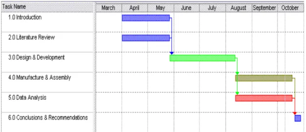
The timeline in the following figure contains the chapters that were completed during the course of this project. Initially the research and literature review chapters were completed together in late May. The design and development
omponent was then completed in August where the manufacturing and assembly compon
c
ents of the following chapter then begun. Data analysis was completed concurrently with the assembly stage in an attempt to identify any potential shortfalls inherent in the design as well as improving overall effectiveness and efficiency of the robot. Conclusions and recommendations were completed in late October with the final submission.
Figure 1.5 Dissertation completion timeline
1.5 Methodology
he research project was divided into chapters, each a sequential step in the process d balancing robot. This approach was tilised in an attempt to progress the project from one task to the next as it was efined so that it builds on the previous task thus evolving the
roject is critical in determining plans for conducting research nd performing the design work. Chapter 2 provides the second step in which a thoroug
T
of developing and building the two wheele u
undertaken. Each is d
robot within the goals and requirements generated. This ultimately led to the completion of the two wheeled balancing robot that met the objectives within the timeframe available.
The first chapter formed the first step where key points and objectives were established including the idea of what a two wheeled balancing robot actually is. Understanding your p
a
The third step in the methodology was to apply the acquired knowledge in key areas so that the control system was achieved with the resources available. Once this was determined, simulation of the stability control system and additional parameters was attempted before settling on the next step of constructing the robot. The simulation task tested the derived sub-routines of the software based controller which was undertaken within the ‘MPLAB’ program. This form of testing provides valuable data on the likely stability capability of the control system. This provides the opportunity to design out faults or shortfalls before resources; time and money are inadvertently wasted. This ensured a complete, well planned, and capable machine was developed.
The next step entailed the manufacture of PCB’s, chassis, drive shafts, etc followed by the process necessary to make the robot a realisation. This was the rewarding section where the hard work finally began evolving into an actual machine. The following step was to analyse the actual performance of the robot and ascertain its ability in achieving the objectives of stability and balance. This also provided the opportunity to calibrate and perform additional fine tuning of the design allowing the machine to become more effective and efficient in its performance.
The final component comprises of a complete assessment of each process undertaken, the choices made and achievements obtained during the project as well as evaluation of the final robots effectiveness. This expanded to include recommendations for future work that could be undertaken in an effort to improve areas of the process or design, addition of capabilities, or how to overcome problems that may have been encountered.
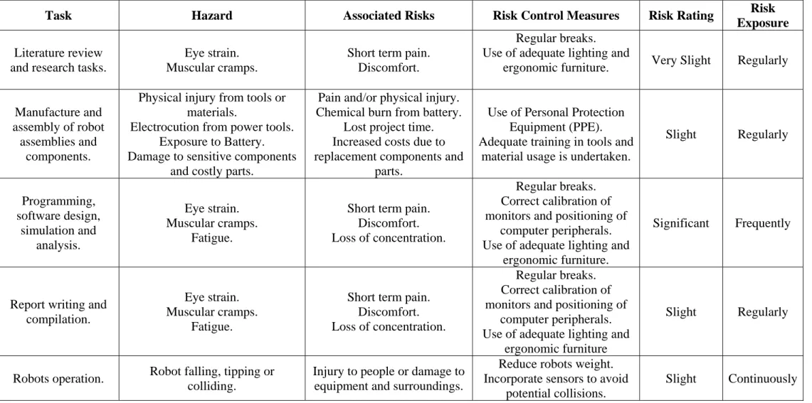
1.6 Risk Assessment
The risk assessment contained within the following table is an assessment of the perceived risks associated with the work to be undertaken in the research project. The table is broken into several components consisting of the task to be performed, the hazard, the associated risks, possible risk control measures, the rating of the risk and potential exposure expected. No substantial risks or hazards are expected during the course of this project. Risk Ratings are defined as follows:
Extremely slight risks are practically impossible to occur.
Very slight risks are unlikely to occur.
Slight risks are possible but unlikely to occur.
Significant risks are possible and likely to occur.
Substantial risks are very likely to occur.
How often the persons involved will be exposed to defined risks is known as risk exposure. These have been defined as follows:
Rarely occurs only few times during the course of the project.
Occasionally occurs once or twice in a month.
Regularly occurs weekly.
Frequently occurs each day.
Task Hazard Associated Risks Risk Control Measures Risk Rating Risk Exposure
Literature review and research tasks.
Eye strain. Muscular cramps.
Short term pain. Discomfort.
Regular breaks. Use of adequate lighting and
ergonomic furniture. Very Slight Regularly
Manufacture and assembly of robot
assemblies and components.
Physical injury from tools or materials.
Electrocution from power tools. Exposure to Battery. Damage to sensitive components
and costly parts.
Pain and/or physical injury. Chemical burn from battery.
Lost project time. Increased costs due to replacement components and
parts.
Use of Personal Protection Equipment (PPE). Adequate training in tools and
material usage is undertaken.
Slight Regularly Programming, software design, simulation and analysis. Eye strain. Muscular cramps. Fatigue.
Short term pain. Discomfort. Loss of concentration.
Regular breaks. Correct calibration of monitors and positioning of
computer peripherals. Use of adequate lighting and
ergonomic furniture.
Significant Frequently
Report writing and compilation.
Eye strain. Muscular cramps.
Fatigue.
Short term pain. Discomfort. Loss of concentration.
Regular breaks. Correct calibration of monitors and positioning of
computer peripherals. Use of adequate lighting and
ergonomic furniture
Slight Regularly
Robots operation. Robot falling, tipping or
colliding.
Injury to people or damage to equipment and surroundings.
Reduce robots weight. Incorporate sensors to avoid
potential collisions.
Slight Continuously
1.7 Conclusion
The dissertation aims to evaluate the process from gathering knowledge in the field of control system and robotics, through to apply them in the design, simulation, manufacture and subsequent analysis of the completed two wheeled balancing robot. A review of the literature available on this type of robot suggests that a non-linear control system has not been readily achieved. This research project achieved a non-linear stability control system based on the fuzzy controller thus proving that this type of system can actually be achieved.
Chapter 2
Literature Review
A two wheeled balancing robot consists of a robot chassis and two wheels. As its name suggests, it has the ability of maintaining an upright “balanced” position which is referred to as its stability. It is unique compared to multi-wheeled or track robots because of this ability. It also has the capacity to turn on the spot making it far easier to manoeuvrer. This makes the two wheeled balancing robot an ideal candidate for working in confined areas or in transportation applications.
This area of research is typically undertaken by engineers and enthusiasts as an approach towards developing their research, design and analysis techniques. This robot is chosen as the inverted pendulum system is naturally unstable and provides a classical control problem. Developing and implementing a suitable stability control system that is responsive, timely and successful can be achieved via linear or non-linear approaches. This chapter reviews the literature that is available in an attempt to gain an understanding and appreciation of two wheeled balancing robots.
2.1 Introduction
A two wheeled robot is basically a robot chassis comprising of a symmetrical shape. This shape can be sectored into several layers where the various components are installed and integrated. Components of the robot may include a core processing unit, sensors, wheels, power source and associated printed circuit board circuitry. If the robot is complex, then additional remote control, autonomous navigations systems, visual or audio recognition systems, etc may be incorporated. The two wheels at the base of the robot chassis provide the locomotion which is typically DC motor driven with gearboxes and shaft encoders affixed.
This type of robot is typically undertaken as a self development process allowing young engineers and robot enthusiasts to learn and develop control systems to satisfy their needs. It also provides a tool for comparing the success of various types of control systems for the typical stability control problem. Segway has led the world with its commercial success of its two wheeled transportation device. As more and more people realise the applications of this type of robot within transportation and beyond, the demand will continue to grow steadily in the future. This includes the field of human mobility.
Two wheeled balancing robots comprise of sensors that provide the ability to see and feel the environment around them. Accelerometers, inclinometers, motor encoders and gyroscopes form the stability and motion sensor families available to provide inputs or feedback to control systems. These include information corresponding to the robots current vertical or horizontal positioning and direction. These inputs can be combined in a process known as sensor fusion. Kalman filter is one type that provides a best approximation from the multiple sensor inputs, allowing the devices inherent inaccuracies to be overcome.
A microcontroller provides the computational power to allow the robot to balance itself, based on the sensor input information. However, the effectiveness is related to the control system that has been implemented. Two different approaches can be undertaken for implementing a control system, they can be either software or hardware based. For this project, a software based control system will be derived. Control systems are further classed as either Linear or Non-Linear control systems. Due to the difficulty and complexity in applying non-linear systems, linear is generally preferred.
Linear systems include State Space control, Proportional Integral and Derivative (PID) controller, Linear Quadratic Regulator (LQR) and pole placement controllers. More recently, developments in non-linear control systems have evolved approaches such as neural networks and fuzzy control. The later will be attempted within this project as non-linear control systems provide a far more effective and efficient controller. The motor driver signals will be enhanced by incorporation of in-line PID controllers.
2.2 Existing Two Wheeled Balancing Robots
Previous two wheeled balancing robot projects include the Segway, nBot, Bender, Emiew and Emiew 2. The Emiew 2 robot is the enhanced (evolved) version of the original Emiew. They were both designed and created by Hitachi whilst the Segway was designed and developed by Dean Kamen who later formed the company Segway Inc. The remaining robots that were reviewed were created by robot enthusiasts who have continued to improve the robustness of their designs over time.
The design concepts between these robots are very similar. Each typically utilise a gyroscope to measure tilt, shaft encoders to measure distance and a microcontroller for performing the computations. These components combine to provide the basis of maintaining stability. Inclinometers or accelerometers are sometimes added to reduce the effects of gyroscope drift thus enabling a more accurate input signal for the control system.
Segway (Segway 2008) is the commercially available two wheeled robot that is currently in its 2nd generation of released models. It is marketed to the world as a transport alternative with the image contained within the following figure. Its advertising suggests the robot is ideal for adventure, commuting, law enforcement and transportation in general. Its trajectory control is based on the tilting direction of the handlebars which is provided by the rider. This robot is capable of achieving a speed of 20 Km/h and is available in Australia for a cost between $9385 and $10795 depending on the model.
Figure 2.1 Segway HTi series two wheeled transport (McComb & Predko 2006) EMIEW (Kageyama 2007) stands for “Excellent Mobility and Interactive Existence as Workmate”. It was the first two wheeled robot produced by Hitachi and was released in March of 2005. It stood at a height of 1.3 m and weighed over 70 Kg. Emiew 2 followed in November 2007 and is approximately half the size of Emiew at 0.8 m and 13 Kg. Its design concept hoped to reduce the safety risks that were associated with Emiew larger size, incorporating reductions in height and weight.
Figure 2.2 Emiew 2 by Hitachi (Kageyama 2007)
David Anderson, an enthusiast, has developed the robot named nBot (Anderson 2007). This robot utilises a gyroscope and accelerometer whose outputs are fused together by a Kalman filter, thus providing an accurate input to control the stability. At present, the robot is in its fourth revision and has the ability of navigating a 7.3 metre distance before returning and repeating the lap once again. One of the strong capabilities of this robot is the ability to transverse rough terrain and even travel down sets of stairs.
Bender (Larson 2008) is a robot made from aluminium and PVC plastics. Its weight is mounted higher in the chassis as it was suggested by Ted Larson that this makes the robot easier to balance. Whilst experimenting with the gyroscope and accelerometer positioning within the robot, he also discovered that the system was much more stable when they were positioned lower in the chassis. These ideas for improving the stability of the robot could be very beneficial during the design phase and initial development.
Other projects on the internet that have not been specified here have presented interesting ideas in the application of the robots construction, control approaches and the resources used. Some robots have been made from Lego blocks whilst others from old materials found around the home. Different approaches to measuring the tilt were also employed with one such robot achieving its tilt measurement through use of paired Infra-Red (IR) sensors. One is place at the front of the undercarriage whilst the other at the back. The distance to the ground is measured by both and then compared for the actual difference. This difference provides the magnitude value whilst the shorter measured distance indicates a tilt in that particular direction.
The majority of these projects have employed linear based control systems in the designs and projects. Many stated that their system did provide a stable system but oscillations about the vertical position were very common. It was also noted that frequent over or under corrections lead to incidences where total loss of stability was experienced. This evidence suggests that robust stability can be achieved if a non-linear approach was undertaken; this project aims to fill this void by providing an insight into the non-linear fuzzy controller, its capabilities and limitations through this application.
2.3 Purpose and Benefits of Two Wheeled Robots
The purpose of two wheeled robots is difficult to limit to a specific role as they can complete numerous tasks with the necessary attachments installed. One purpose could be to access a hazardous or confined environment which would be difficult to manoeuvrer around for a track or multi-wheeled vehicle. This is easily achieved by a two wheel robot as it can turn on the spot by rotating the right wheel forward whilst the left rotates backward and vice versa.
They could be controlled remotely or autonomously, depending on the terrain and frequency of obstacles around them. In cities and communal areas of society, it is very common for recreational, social and vocational areas to be reasonably flat, therefore traction would be the main concern. Waterways and very rough terrain would be the only problem with this current level of design. Society could benefit substantially from sharing their environment with two wheeled robot assistants. The following roles are only a small sample of the greater potential of possibility.
A robot could fulfil the role of a home health assistant as it doe not require rest. It could provide 24 Hr comfort for families with sick or elderly members. They could easily manoeuvre about the home and provide wireless connectivity to the internet or private networks. This could be used to raise alarms if an incident occurs or if other additional sensors such as a heart monitor enter an alarm state. A built in camera, speaker and microphone could provide a means of communication for medical personnel online, direct to the patient.
It could be utilised as a warehouse tracking robot where item statuses can be easily tracked as part of a schedule, or manually when requested by clients. It could automatically update the companies system and databases through a wireless connection. Other available features would be the ability to perform audits, stock checks as well as conduct security tasks whilst on duty within the warehouse environment.
In a fire warden role, the robot could access a smoke filled area and evaluate the risks before any human lives would be placed in danger. A camera would provide visual images to the fire commander whilst temperature sensors would measure hot spots on bulkheads, deck heads and flooring. IR sensors could search for trapped people or living creatures and provide mapping of obstacles within the room. All indications, measurements and information could be relayed directly to fire commanders allowing a swift and effective effort to prevent life loss and reduce potential damage.
Another purpose could be a general communication robot. They would perform the tasks of a travelling telephone, videophone, fax, Voice Over IP (VOIP), MSN messenger or interface for any other messaging means that may become available in the future. When it receives a call request, it could utilise it sensors to locate the person by itself. Room sensors could be wirelessly integrated with the robot so it can easily identify people within a larger area. This could also be extended to include the detection of intruders where the robot would investigate detections before raising the alarm with authorities.
2.4 Modes of Operation and Control
Autonomous operation is the goal of most robot developers. Being autonomous suggests the robot is capable of making the decisions itself and performing the necessary actions. It is self-directed and self reliant. This type of control system is self contained with no outside control interaction from humans. Autonomous systems are typically difficult to implement due to the complexity of inputs and outputs, and the variables available. Common problems are associated with the sensitivity, responsiveness and other reactive factors of the components used within the final system.
Non-autonomous operation is much easier to implement as a human still makes the decisions on what actions to undertake. This is typically achieved via remote control facilities for the human. Within the two wheeled balancing robot projects encountered during the literature review, it can be seen that stability control is normally autonomous controlled whilst the trajectory is predominantly non-autonomous based. Sensory such as cameras and radar devices could provide terrain identification and object detection to assist an autonomous trajectory design but this is outside the scope of this project due to time constraints.
2.5 Implications and Ethics of Technology
Implications of technologies, especially associated with robotics, bring a fear that people will no longer be competitive for employment opportunities, particularly, in the future. This idea is encouraged with the offer of cheap labour robots that are slowly becoming available in the marketplace. Although this appears to be true on face value, the majority of jobs that robots are undertaking include those that people consider to be hard labour, repetitive and hazardous.
Reducing the exposure of people to harmful chemicals, environments and conditions as well as the risk of physical injury should be embraced by society. A robot can easily have parts replaced if an incident occurs but replacing an arm for a human is not quite as simple. This idea also applies with repetitive tasks were human workers may become fatigued or bored which ultimately leads to mistakes or potentially fatal errors. These mistakes can cause significant resource and time loss for a company or organisation. This is easily avoided by using robots as they don’t become bored and with adequate maintenance schedules in place, they will remain accurate and precise in performing their roles with minimal downtime.
Other implications suggest that robots could fulfil roles of personal assistants, carers and helpers thus reducing the stress and workloads of families living with disability or medical conditions. This would reduce medical and household costs further decreasing burdens on families and people in general. This could also extend to the public health system where each person receiving treatment can be monitored and attended to for 100% of the time. Quality of life could also be improved for those who lack the ability of motion. People around the world will have the ability to retain their independence, even into the later years of their lives.
Negative implications may occur if corporations or governments begin eliminating a large volume of human job positions without creating positions in other fields/areas. Unfortunately, this relies on all members of society accepting their moral and ethical responsibilities and obligations as people of the community. This can be achieved by implementing law to protect this from occurring. There is some potential for negative impacts due to negligent use of the technology but the positive gains within all levels of society far exceed any perceived risks.
2.6 Conclusion
Two wheeled balancing robots consist of a robot chassis, two wheels and a stability control system. Additional components and attachments may be fitted depending on the task required to be performed. There strengths lie in the ability to turn on the spot and easily manoeuvre in confined areas. Stability is achieved by keeping the wheels beneath the mass of the robot chassis. Utilising a non-linear control system for stability will allow a more effective and robust control to be implemented.
Chapter 3
Design and Development
The design phase of a project is fundamental in evolving the ideas, requirements and objectives of the components that together, will form the completed robot. Development and careful design considerations provide the engineer with the ability of ensuring that the concept remains viable as it progresses. It also provides the opportunity to make continued improvements in its operation, ensuring that obvious problems and potential faults are removed early in the project. This ultimately saves valuable time and resources over the duration of the project.
3.1 Introduction
The literature review conducted in the previous chapter provided a wealth of information on past robotic projects that had been completed by enthusiast and engineers alike. This indicated that linear control systems with remote controlled locomotion were very common which inspired this project to undertake a completely different approach. This revolved around a design based on a non-linear fuzzy controller for stability. The review provided ideas and consideration which will be explored in the following sections of this chapter. These include how it will move, how it will sense the environment around it, how it will be powered and what it will be made from.
The two wheeled balancing robot will be broken into two distinctive components of operation. The first is the balancing component “Microcontroller system” which will fulfil the fundamental goals of the project. This encompasses the sensors, chassis, locomotion and microcontroller with its associated control system. The second involves the interaction of the robot with the controller as well as with people it may encounter. This component is called the “Interaction system” and encompasses the wireless network connectivity, interaction computer, audio components and web cameras.
3.2 Control System
Advancements in non-linear control systems such as neural networks and fuzzy controllers present the opportunity for developing far superior, responsive control systems. Non-linear is the preferred control system for this robot as a reliable, robust and stable platform can be achieved. There are several types of fuzzy controllers derived to date including the direct fuzzy (non-adaptive), adaptive, fixed and supervisory fuzzy controllers.
The fuzzy controller operates differently to these classical linear controllers as it refers to a set of rules to provide a range of responses, rather then a single predetermined output variation to the input. The input of the fuzzy controller undergoes fuzzification upon entry. Fuzzification is the process of modifying the input into the required rule base format. The inference mechanism then determines which set of rules are referred to for deciding on the necessary output response. Once this resultant action is determined, it then undergoes defuzzification before being outputted to the system under control.
Ideally, adaptive fuzzy control would have been chosen as it is capable of learning how to improve its performance but it had to be overlooked due to time constraints. This is achieved by comparing the output response and the corresponding feedback values returned to the controller. By monitoring and reducing system errors, the controller will learn to control more effective and efficiently then it would by utilising its default rule set. The idea of combining several fuzzy controllers was also contemplated but the risk of increased complexity and difficulty controlling changes was too large. These cascaded systems could have comprised of speed, stability and locomotion controllers.
The goal of the fuzzy controller being implemented is to be capable of recovering from deliberately induced tilt above the rate of 15o per second. These results are not easily realized under linear control systems thus a fuzzy controller approach is preferred. Choosing a sampling rate that will be capable of performing successfully was taken on the principle of Nyquist sampling theorem. This suggests that the sampling rate is twice that of the highest operating frequency of the system.
Size Value Input 1 (rad)
Input 2 (rad/s)
Input 3 (m)
Input 4 (m/s)
Output (%) Negative Large (NL) 1 -pi/5 -5 -0.1 -0.45 -100 Negative Medium (NM) 2 -pi/9 -2 -0.07 -0.3 -70
Negative Small (NS) 3 -pi/28 -1 -0.04 -0.15 -30
Centre (CE) 4 0 0 0 0 0
Positive Small (PS) 5 pi/28 1 0.04 0.15 30 Positive Medium (PM) 6 pi/9 2 0.07 0.3 70 Positive Large (PL) 7 pi/5 5 0.1 0.45 100 Table 3.1 Fuzzy controller membership functions
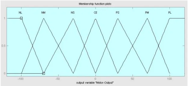
For the system to be balanced at equilibrium, all four inputs are ideally at zero. The fuzzy process encompasses seven memberships for rating the strength of the inputs within this system and is contained in the previous table. These memberships are then incorporated with each of the inputs and output to form functions known as membership functions. The name of these types of membership functions comes from its shape, such as triangular which was chosen for this project.
Triangular, trapezoid, gaussian and bell membership functions are a few that may be produced. They represent linguistic values such as positive large through to negative large with a minium, maximum and centre value. The shape they undertake reflects how the values a portrayed. This is particularly important as centroid of area was used in the defuzzification of the triangular output membership function. This allowed an actual value to be selected based on the fuzzy rule set.
Figure 3.2 Input 2 - Angular velocity membership function
Figure 3.3 Input 3 - Displacement membership function
Figure 3.5 Output – Motor output membership function
The previous figures contain the visual representations of the respective membership functions. As seven membership functions were decided on for each of the four inputs, 2401 conjunctive rules (7*7*7*7=2401) would be required. This was reduced to approximately 427 rules by giving the vertical inputs a higher priority, as maintaining a small vertical angle is crucial for preserving stability. The horizontal inputs are only enacted upon when the vertical is in a centred state. It is essential to reduce the rule set as much as possible as its size directly impacts on the processing time necessary to search it.
Angle Angular
Velocity NL NM NS CE PS PM PL
NL PL PL PM PM PS PS CE
NM PL PM PM PS PS CE NS
NS PM PM PS PS CE NS NS
CE PM PS PS CE NS NS NM
PS PS PS CE NS NS NM NM
PM PS CE NS NS NM NM NL
PL CE NS NS NM NM NL NL
Displacement
Velocity NL NM NS CE PS PM PL
NL PM PM PM PS PS PS CE
NM PM PM PS PS PS CE NS
NS PM PS PS PS CE NS NS
CE PS PS PS CE NS NS NS
PS PS PS CE NS NS NS NM
PM PS CE NS NS NS NM NM
PL CE NS NS NS NM NM NM
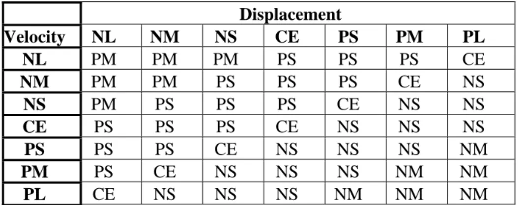
Table 3.3 Displacement and velocity rule relationship
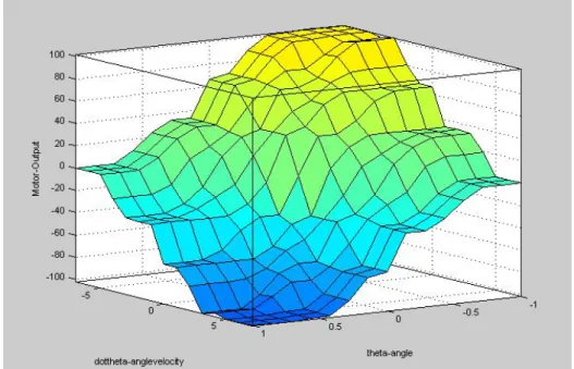
The previous tables contain the rule relationships of the vertical and horizontal input sets respectively. This provides the fundamental component of the rule base. For example, if the angle and angular velocity were both negative medium, then a response of positive medium is required at the motors. If the output required was nil (centre), then the horizontal relationship would provide the output response. The defuzzification method known a Centroid of Area (COA) was the preferred method for the output as it allows an accurate translation to real output values. With the output already scaled between 0 and 100, this could be translated directly to the percentage of PWM required.
Figure 3.6 Angle and angular velocity rule set surface plot
Figure 3.7 Displacement and velocity rule set surface plot
3.3 Software and Programming Concept
When a software program appears to be performing numerous tasks seamlessly, it usually contains several programs working in conjunction. To achieve this, programs are again broken into routines and sub-routines which reduce the overall size of the main program. This improves efficiency and responsiveness by only calling blocks of programming that are necessary for the specific task at hand. This has the effect of reducing the microcontrollers processing time.
The programming necessary for the two wheeled robot encompasses the microcontroller and interaction systems. The microcontroller is required to read in an assortment of sensors, provide computation on these inputs, make a judgement on the necessary actions to undertake and then respond by providing drive signals to the motors. This is purely to enact stability and locomotion control programming. The programming was completed in C programming language and then compiled for the microcontroller by the software tool, MPLAB.
The programming goal of the interaction system was to incorporate a wireless (WiFi) connection thus allowing remote locomotion control, access to onboard sound and visual devices, and to provide a means of reprogramming the microcontroller. The Microsoft Robotics development Studio package would have provided the programming tool using visual basic programming techniques. This component was not completed due to the timeframe but it will be endeavoured in the future.
Figure 3.8 Microcontroller structure chart
Figure 3.9 Microcontroller main program flowchart
The main program begins with an ‘Initialise’ block which sets up the stored values and lookup tables. This block is only executed upon start-up or reset. The remainder of the looped program contains four main sub-routines and a decision block. The sub-routines are discussed in the subsequent paragraphs below. The decision block has been incorporated to determine if the bumper collision switches have been activated.
Upon activation the program will end causing the robot to stop driving the motors, thus releasing any driving force that may have been applied. The program may be reinitialised at this point by resetting the microcontroller. If the switches are not activated, then the program will continue through the looped ‘while’ sequence.
Sub-routine ‘Locomotion Desired’ reads the user provided forward, backward, left and right direction control signals. The following two blocks then determine a resultant left and right motor response respectively, which is stored for use within the next locomotion sub-routine. These values are also used within the subsequent block to derive an offset value for the vertical angle measurement. This will allow the robot chassis to be tilted into the direction of desired travel thus allowing more torque to be achieved.
Figure 3.10 Sensors and locomotion desired sub-routine flowcharts
The ‘Fuzzy Control’ sub-routine forms the core of the control system. The initial block converts the stability values to there respective equivalent linguistic membership values. The next block then compares these values with the rule set to determine the desired output response for the motors. The remaining block then performs a defuzzification to arrive at a motor output signal response.
Figure 3.11 Fuzzy control and locomotion response sub-routine flowcharts
3.4 Design Considerations
Design considerations are an important factor when compiling a design because they facilitate an informed decision on the limitations, operating conditions and capabilities of the final product. This process may also highlight areas for further investigation that could improve, simplify or make a product more cost effective. This includes commercial aspects that may be undertaken if the product was to become mass produced or if an alternate material or component usage was to be implemented to reduce the potential manufacturing costs.
Design considerations for the two wheeled robot encompassed operating environments, motors, wheels, sensors, microcontroller, communications, power source, safety features, electromagnetic factors and various forms of control. All these considerations were then sub-investigated to determine dimensions, configuration, temperature parameters, maintenance requirements, availability, efficiency, etc. Consideration of these factors combine together to guarantee the necessary capability is achieved successfully within the timeframe and resources available.
3.4.1 Operating Environments
The operating environment of the machine refers the conditions under which it will be performing its tasks. Primarily, this can be broken down into two main environments, indoors and outdoors. The outdoor environment would be much more hash with exposure to numerous varieties of weather including rain and hail. Temperature variation could be as much as 50oC and when combined with continuous direct sunlight, could pose serious performance degrading if a robust design was not incorporated.
An indoor design proves to be a simpler process as the environment is normally regulated by air-conditioners. This also reduces the expose to dust and dirt particles, direct wetting and even direct sunlight (UV). The terrain is also smoother when compared to the rough outdoors through paving, carpeting and tiling. Neglecting to adequately prepare a machine for its operating environment may lead to premature breakdown, potential safety implication and loss of productivity in a commercial situation.
The maximum temperature expected is approximately 60oC. This remains below the rated maximum temperatures of IC’s, components, cable and part ratings. Direct sun could raise the temperature beyond this posing a potential problem unless cooling is implemented within the robot chassis but this will not be pursued. Vibration would remain manageable for the final size and weight of the robot. Extra care was taken in reducing the vibration risk by securely fastening all components and circuitry in place as well as the inclusion of rubber matting between the motors and chassis.
3.4.2 Materials, Size and Weight
The materials used in a design limit the durability, strength, maintainability, energy efficiency and operating capability of the product. They also impact on the size and contribute to the total weight of the final design. A heavier material such a metal is typically stronger then lighter materials such as plastics but it requires more energy to move. The size of the design impacts on its ability to navigate around, through or over obstacles as well as its transportability.
Materials that could have been used in the robots construction include metals, alloys, wood, plastics and other synthetics. Heavier metals were excluded early due to the increased weight that would impair the stability control of the robot. Although wood was an option, it is a potential ignition source in higher temperatures and is also very difficult to mould. Rubber strips could also be utilised in the shock resistant precautions that may be experienced from falls, bumps or rough terrain but this was only incorporated to support the battery and motors within their mounts.
As the robot will be utilised in a people environment, a maximum height of 0.8 m was chosen as it approximates to a child’s height. The robot chassis has a multi-platform layout where each platform (layer) contains a unique component of the robot systems. An average height of 120 mm will separate each layer with the exception of the power level due to the limited battery sizes available. This is 150 mm. Additional layers could be added to the top of the chassis, permitting easy expansion of the robots capabilities thus allowing greater flexibility for adaptability and enhancements.
Several options are available for joining the chassis pieces together such as bolts, screws and welding but rivets were the preferred method in this case. Epoxy adhesives were utilised in joining the plastic pieces together. Additional plastic brackets were manufactured to attach sensors and PCB’s which were also affixed into place with epoxy. The completed chassis weight goal was initially 5 Kg but this was exceeded by 1 Kg by the final manufactured product. The weight values were calculated for each respective layer as follows:
Upper layer, 0.5 Kg,
Interactive system layer, 0.5 Kg,
Power layer, 7 Kg,
Spare layer 0 Kg,
Microcontroller layer 1 Kg,
Motor & wheels level, 2.5 Kg,
Chassis structure, 6 Kg,
TOTAL combined weight, 17.5 Kg.
An outer skin layer such as a thin plastic sheeting (1-2 mm) could be applied to the robot allowing a sleek appearance. The sensors would require that the outer skin is cut to allow proximity detection, etc. Removable panels would be required to allow the maintainer or operator to access certain areas of the robot for maintenance and connection of peripherals. This option has not been pursued.
To improve the ability to balance, the aim was to place the larger weights higher in the chassis layers. This principle can be equated to balancing a broom in the palm of your hand. When the broom head is within your palm and the handle upwards, it is difficult to maintain the length in a vertical position. Reattempting this task with the handle in your palm and the broom head high proves far easier to balance. Another goal was to centre the weight over the wheel axles, for each layer, to contribute to the stability of the robot.
The battery acts as a destabilising influence on the system due to its large weight of 7 Kg in the upper half of the robot chassis. This allows the robot to maintain stability easier as more torque can now be generated. Total weight of the robot was initially set at a maximum value of 15 Kg but this was overshoot by a total of 2.5 Kg.
3.4.3 Wheels
To overcome poor traction, higher levels of torque are required which is ultimately supplied by the motor. Ideally the tyre traction would have maximum contact with the ground and minimal resistance through the drive system. A width between 30-45 mm of a rubber tread was deemed acceptable as it would provide reasonable grip for most terrains and weather conditions. It would also prove ideal for turning on the spot which is a major feature of a two wheeled balancing robot.
Each of the two wheels will be independently controlled in either direction by a dedicated motor. The wheel could potentially have a large diameter such as a bicycle wheel but this would prove impractical for manoeuvring in confined areas or indoors. The diameter required for the wheels was approximated between 150-190 mm so that proportionality could be maintained with the anticipated robot height of 800 mm and weight of 17.5 Kg. The diameter played an important factor in the torque calculations that are further discussed within the motor section that follows.
Two plastic wheels with solid rubber tyres were chosen due to there reduced cost and lower associated weight compared to its metal counterparts. The wheel diameter was 187 mm with a tyre width of 40 mm. As the tyre is solid, it is not susceptible to being punctured although this tyre will likely increase the vibration experienced by the onboard circuitry if rough terrain was encountered.
3.4.4 Motors
Motors are an essential component for providing mobility. Without motors to move the machine, it would prove to be an expensive paperweight. Several types of motor are available including Alternating Current (AC) or Direct Current (DC) types. Variances of these motors include the brushless, brush, servo and permanent magnet motors. Another consideration for the motor is its Revolutions Per Minute (RPM). As most motors are rated between 2000-7000 RPM, some form of gearing is required to reduce the rate experienced at the wheel.
Figure 3.13 Differential drive motion
As the right motor moves forward and the left motor moves backwards, the robot chassis will be turned to the left. If equal torque is applied to each of the motors, the robot will turn on the spot. The same principle applies if both of the motor directions are reversed. If the left motor turns forward whilst the right motor turns backwards, then the robot will turn to the right. If both motors are moving forward, then the robot will move forward and vice versa. Other considerations for the turning of the robot should include the angle of the robot chassis. With this in mind, the main goal would be to tilt the chassis in the direction the robot is about to travel.
A supply voltage of 12V was chosen for the motors although 6V and 24V are also fairly common voltages. The motors would be better mounted under the robot chassis to allow a higher clearance from the ground. Otherwise the lower chassis layer may drag into the ground at a very lower angle of tilt. Stepper motors are too slow to react due to the actually stepping action and will not be capable of balancing the robot efficiently. A motor with a high volume of torque was a necessity with the final choice being two HG37D670WE12-052 DC Brush motors with a 1:52 gear head and shaft encoders fitted.
The required torque for the robot can be reduced by leaning forward into the direction of anticipated travel. This will be attempted within the control system design component. The RPM estimation of the motor is 160 RPM. With the chosen wheel diameter of 187mm, the expected approximated maximum speed is 5.64 km/h. For a rated motor torque of 7.1Kg/cm, the anticipated acceleration at the rated input voltage is 0.086 m/s2.
Velocity, 1.57 1
60 160 * * 187 . 0 60 * *
d RPM ms
v WH
1 64 . 5 1000 3600 * 57 .
1
kmh
v
Motor force, 1
759 . 0 2 7 . 18 1 .
7
Acceleration, 0.086 2 75 . 8 759 . 0 2 cms mass F a
Power, P V*I T*rps 7.1*2.6719W
The motors have shaft encoders incorporated into their case, rated as 12 pulses per motor revolution or 624 pulses per shaft revolution. Shaft encoders are necessary to obtain linear position measurements before the velocity calculations may be performed. They are covered further under the sensor section within this chapter. Although the retailer recommended a 7.2 V input, the manufacturer “Hennkwell” rated the motors input between 6 and 24V. It was concluded that 12V may be safely applied in its operation. The additional voltage is expected to provide much needed torque to move the total weight of 17.5 Kg.
Motor Control
Motor controllers control the motors rate of turn and its direction by varying the output voltage signal and setting its polarity respectively. There a several forms of motor control with the application dependant on the role and the motor in use. Direct, Relay, transistor or H-bridge (motor bridge) controllers are all common types available. The later provides the facility for a pulse width modulation (PWM) signal output for varying the motor speed.
PWM provides an output voltage that is varied by a duty cycle. This duty cycle is a percentage of voltage time high compared to voltage output and specifies the ‘pulse width’. The speed of the motor is altered by altering this duty cycle percentage. A benefit of this approach is that there is no digital to analogue conversion necessary so there is no potential for induced noise or interference on the signal. It is recommended (McComb & Predko 2006) that PWM is run at frequencies over 18 KHz, higher than the maximum human hearing frequency, to avoid hum noise generation within the motors.
For controlling the robots motors, PWM will provide the best option as using direct voltage level inputs may cause the robot to ‘hunt’ about its position. This occurs as the equilibrium point is exceeded consistently in either direction thus causing an oscillating effect. The microcontroller cannot drive the motors directly at the necessary current so a H-bridge, called this due to its transistor configuration, will boost the PWM signal to the motor. Smaller motor control changes such as those in PWM, reduce the robots power requirements hence it is an added improvement to the robots design.
Figure 3.14 L298 motor driver PCB (Solarbotics)
The H-bridge circuit also offers LED indication of the direction each motor is driven as well as an additional regulated 5V power supply output. This proved beneficial for isolating the gyroscope circuitry from the main 5V distribution and reducing the gyroscopes EMI impact on the system. The control inputs to the driver allow forward or reverse rotation as well as braking of the motors. Another benefit of the motor driver is the thermal shutdown protection incorporated into the PCB. 3.4.5 Sensors
Sensors provide the robot with the ability to interpret the environment around them. Without sensors, the robot would blindly execute a series of instructions without the capacity to re-evaluate its progress and make adjustments. Sensors are available in two forms, analogue and digital. Analogue sensors provide a range of values in response to its sensitivity which have the benefits of measuring rates or volumes. Digital sensors only provide an on or off value and are ideal for an absolute indication. Sensors may be connected by parallel or serial connections to the microcontroller or Analogue to Digital Converters (ADC) depending on the actual sensor used.
Accelerometers, gyroscopes and inclinometers are the most common types of sensors utilised in robots and machines that require stability control. They provide a means of measuring acceleration, velocity and direction. If multiple axes were to be measured with certain type of sensor then a sensor would be required for each particular axis. By combining different sensors through a process known as sensor fusion, certain sensor problems such as gyroscope drift and noise can be overcome and kept within the required accuracy. Commonly, a gyroscope and inclinometer are combined.
Other forms of sensors include contact sensors to detect a bump with an object, light sensors to detect lighting changes or conditions, thermal sensors to detect temperature variation and sound sensors that can detect the presence of sound waves. Contact sensors will be incorporated into the robots design to stop the robot moving in any direction. This is aimed at preventing damage to obstacles or injury to people. The five most common sensors used in robotic design are IR, accelerometers, gyroscopes, inclinometers and shaft encoders.
The sensor requirements for the project include inertial sensors for stability sensing, proximity detection for object detection and bumper sensors for contact detection. An accelerometer, gyroscope and shaft encoders form the inertial sensors. IR sensors form the proximity detection whilst standard bumper switches provide the contact detection. They are discussed further in the following paragraphs.
Accelerometers
Accelerometers provide a means of measuring acceleration along an axis, also known as force. They are susceptible to position noise which can be avoided by incorporating filtering on their digital or PWM output lines. Accelerometers are commonly found in airbag and braking control systems of vehicles. Their main purpose is to measure changes in speed. It is classed as an analogue device as the voltage varies with respect to the rate of change.
This device will be used to determine the change in speed with relation to the robots tilt, its change in acceleration. The model chosen was the ADXL311JE accelerometer provided by Excelpoint, NSW. It is specified as a high shock resistant, low power, dual axis accelerometer. This model provides a bandwidth capabili