This is a repository copy of
Spectrum splitting-based cognitive interference management
in two-tier LTE networks
.
White Rose Research Online URL for this paper:
http://eprints.whiterose.ac.uk/84539/
Version: Accepted Version
Proceedings Paper:
Siswanto, D, Zhang, L and Navaie, K (2014) Spectrum splitting-based cognitive
interference management in two-tier LTE networks. In: 2014 11th International Symposium
on Wireless Communications Systems, ISWCS 2014 - Proceedings. 11th International
Symposium on Wireless Communications Systems, 26-29 Aug 2014, Barcelona, Spain.
Institute of Electrical and Electronics Engineers , 613 - 617. ISBN 978-1-4799-5863-4
https://doi.org/10.1109/ISWCS.2014.6933427
[email protected] https://eprints.whiterose.ac.uk/
Reuse
Unless indicated otherwise, fulltext items are protected by copyright with all rights reserved. The copyright exception in section 29 of the Copyright, Designs and Patents Act 1988 allows the making of a single copy solely for the purpose of non-commercial research or private study within the limits of fair dealing. The publisher or other rights-holder may allow further reproduction and re-use of this version - refer to the White Rose Research Online record for this item. Where records identify the publisher as the copyright holder, users can verify any specific terms of use on the publisher’s website.
Takedown
If you consider content in White Rose Research Online to be in breach of UK law, please notify us by
Spectrum Splitting-Based Cognitive Interference
Management in Two-Tier LTE Networks
Diky Siswanto, Li Zhang, Keivan Navaie
School of Electronic and Electrical Engineering, University of Leeds, Leeds, LS2 9JT, UK Email:{elds, l.x.zhang, k.navaie}@leeds.ac.uk
Abstract—In this paper, we propose a spectrum splitting-based cognitive interference management method for LTE downlink two-tier networks (that provide closed-access mode). In the pro-posed method, the resource-blocks in the macrocell (in frequency and time domain) are allocated to the users with the received signal-to-interference-plus-noise-ratio greater than a threshold. The rest of resource-blocks are then allocated to the femtocells. To evaluate the effectiveness of this method, we develop a system level simulation and compare the proposed method with no interference management and also interfering resource blocking-based cognitive interference management method (IRB-CIM). It is shown that the proposed method significantly increases average throughput of femtocells’ cell-edges. Furthermore, the simulation results indicate that by adjusting parameters, the proposed method results in higher average throughput for femtocells and for overall system compared to other methods. The proposed method senses control-channel of the macrocell to detect spectrum availability which is simpler and faster than IRB-CIM.
I. INTRODUCTION
Femtocells allow the service providers to extend their ser-vice coverage area to indoor as well as in the cell edges. With the presence of femtocells, cellular network providers expect to have benefit of extending the coverage area, increasing the capacity and improving the service performance as well as enhancing the spectrum efficiency. In such development, in-terference is a critical issue since the femtocells reuse the same spectrum which is already allocated to the macrocells. There-fore, the femtocells have potential of introducing interference into the main macrocell network as network users can install femtocell access points in any place without coordinating with the wireless network provider.
Two-tier networks are wireless systems comprising of a(some) macro-cellular network(s) being underlain by smaller coverage femtocells. Interference in two-tier networks includes cross-layer interference, which occurs between a femtocell and a macrocell, and co-layer interference, which occurs among network elements that belong to the same network layer.
To mitigate the interference impact in two-tier networks, in-terference management can be performed either in the macro-cell or the femtomacro-cell layer. Generally, interference management techniques can be classified into: (a) Interference cancellation: demodulating desired information and then using it along with channel estimates to cancel interference out from the received signal being defined, e.g. SIC, PIC, and MUD [1], [2].
978-1-4799-5863-4/14/$31.00 c2014 IEEE
Most of these methods require information of the characteris-tics of the interfering signal and antenna arrays at the receiver system. Therefore, these methods are less suitable for user-equipments (UEs); but more suitable for base stations (BSs) so they are generally used for uplink interference management [1]. (b) Interference randomization: mitigating interference by dynamically and periodically allocating different times or frequency to users, e.g. time [1] and frequency hopping [3].
These approaches need high synchronisation between a BS and a UE as well as not considering channel gain. They will be more complicated when femtocells are deployed densely. (c) Interference avoidance: managing radio resources in such a manner to avoid the impact of interference, e.g. frequency reuse/ spectrum splitting [1], power control [4], and spectrum arrangement [5]. However, these schemes are based on central-istic controlled process, less efficient in spectrum utilization, femto-BSs (FBSs) load will increase when the number of macro-UEs (MUEs) is high and spectrum occupation fluc-tuates, and also the macro-BS (MBS) needs information of its underlying FBSs.(d) Distributed interference management [6]: each BS has ability to control its radio resources. This approach needs information exchange and coordination be-tween two network tiers. Therefore, this method will increase systems’ overhead as the number of femtocells rises up.
Nevertheless, each method above has its own advantages for specific interference problem. Since a femtocell is surrounded by varied and complicated environment as well as dynamic wireless channels, implementing one method above does not guarantee resulting in optimum performance in a wireless system. To combine a number of advantages in different methods, recently researchers have integrated a cognitive radio concept into interference management methods [7]. In this way, the methods will be aware of its environment and adaptive to statistical variations in the input stimuli, with two primary objectives of highly reliable communication and efficient utilization of the radio spectrum [8].
Along with the increasing number of BSs and UEs, the system’s complexity and overhead will also increase. This is mainly due to the information exchange process among interfering and interfered BSs. In addition, to determine which RBs will be blocked, the method did not consider the quality of each RB. Therefore, each BS will possibly block good RBs and utilise the bad ones.
To simplify and speed up information exchange among base-stations as well as to address the above problem, we propose a spectrum splitting-based cognitive interference man-agement method (SS-CIM) for LTE downlink-channel. The proposed method handles RB allocation by considering its radio environment and splitting the spectrum for different tiers in the networks. In the proposed technique, an MBS analyses the channel state information from each user then identifies the RBs in which the SINR is below the threshold and blocks them accordingly. FBSs then sense the control-channel from the MBS and allocate RBs which are blocked by macrocells. Base on RB allocation map, both two-tier networks allocate RBs and schedule access to their served users. It is assumed that each BS provides closed-access to its served user devices. We use Monte Carlo simulation to evaluate the performance of the proposed method; then compare the results with non-interference management (NIM) and IRB-CIM [9]. In our simulation, cumulative distribution functions (CDF) for SINR and for throughput are utilized to indicate the effectiveness of interference management as well as system performance improvement. Furthermore, the average throughput of cell-edges (5thpercentile) and the total throughput are calculated
to show how much improvement can be achieved.
II. SYSTEMMODEL
The system model consists of two-layer cellular networks, comprising a macro and a number of femto-cells that uni-formly are distributed on the same coverage area. The MBS serves MUEs which are uniformly distributed in its coverage area. Likewise, each FBS serves a number of femto-UEs (FUEs) in each coverage area. Furthermore, each BS provides closed-access type, which only gives access to users in its access list. The users’ position is assumed being fitted.
To determine which users occupy limited bandwidth at dif-ferent times, proportional fair scheduler is used in both macro and femto networks. It is assumed that perfect synchronization is available among all cells for both frequency and time aspect. FBSs sense the control-channel information of the macrocell to determine RBs being allocated for their users. Flat energy distribution over the entire bandwidth is implemented for all cells in the system. Omni-directional antennas are used in BSs and UEs for both macro and femto-cells.
III. SPECTRUMSPLITTING-BASEDCOGNITIVE
INTERFERENCEMANAGEMENT
[image:3.595.304.553.56.206.2]We propose SS-CIM via dynamic RB allocation for both macro and femto-cell tiers. In this method, the macrocell allocates RBs based on the SINR level of the reference-signal-received-power (RSRP) of its served UEs. By blocking some
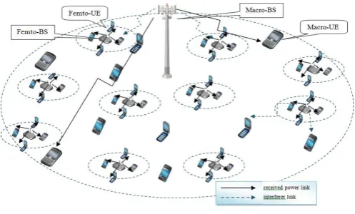
Fig. 1. Network Layout
RBs with SINR lower than a threshold, the MBS allocates good RBs for MUEs. Then scheduler distributes the RBs to each user in different times. Whilst, based on the control-channel information from the MBS, FBSs allocate RBs that are not occupied by the macrocell to serve its users.
A. SINR Level Identification and Spectrum Splitting
In this step, the MBS identifies each RSRP being received from all MUEs and marks RBs with SINR lower than thresh-old as ‘1’, as shown in Table I. Based on Table I, the MBS counts the number of users with low SINR (weak users) in each RB. After that, it orders the number of weak users of each RB. Then it chooses a threshold ϕ, a parameter which can be set by the algorithm. When the RB has a number of weak users aboveϕ, it will be blocked. Subsequently, the MBS determines RBs to be blocked by prioritizing RBs with high number of weak users.
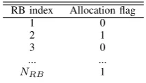
All processes above will result a RB allocation map as shown in Table II. Flag ‘1’ represents a RB being allocated to the macrocell. Algorithm 1 summarizes all process above.
B. Control-Channel Information Sensing
In this step, all femtocells simultaneously sense the control-channel information (PDCCH) from the MBS. PDCCH from the MBS holds information of RB allocation for all MUEs in one sub-frame. FBSs use this information to observe RBs being occupied by the MBS, and find out unoccupied ones to allocate to their served users. Based on this, each FBS generates its RB allocation map (Table II ).
C. Frame-based Transmission and Scheduling
Based on Table II, the scheduler in each BS (both macro and femto-cells) will allocate RBs to its served UEs for downlink transmission. By using a multicarrier proportional fair (PF) scheduler [10], the distribution of RBs among users in frequency and time domain can be maintained proportionally.
TABLE I
WEAKRESOURCEBLOCKMATRIX
RB1 RB2 RB3 ... RBk
U E1 1 0 1 ... 0
U E2 0 1 1 ... 0
TABLE II
RESOURCEBLOCK ALLOCATION MAP
RB index Allocation flag
1 0
2 1
3 0
... ...
NRB 1
D. Algorithm Summary
In general, the RB allocation procedure in the macrocell can be summarized as follows.
Algorithm 1RB allocation in the macrocell Step 0:ρ= ones(NRB,1);
Step 1:f ind(γik< γth);
Step 2:if γik< γththenψik= 1, elseψik= 0;
Step 3:Ψ=P
k ψik;
Step 4:θ={Ψi}i∈{1,...,n},Ψi∈ {Ψ},Ψi6= 0,
Ψi6= Ψjfor i6=j;
Step 5:θsorted=sort(θ,‘descend’);
Step 6:ϕ= n
Nwu
, n={a < Nwu:a∈N};
Step 7:λ=⌊ϕ×n(θ)⌋; Step 8:f or k= 1to λ
f ind(m|Ψm=θsorted,k), m∈ {∅,1, ..., NRB}; ρm= 0;
Step 9:end
whereρis a RB allocation map as presented in Table II;NRB
is total number of RBs;Nwu is a maximum number of weak
users in each RB;γikis the SINR received by user-kon RB-i; γthis an SINR threshold;ψis a weak RB matrix as presented
in Table I;Ψ is a vector, representing the sum of weak RBs of all MUEs;n(·)is the number of elements of the set.
IV. SIMULATIONSETUP
In this paper, we simulate two-tier OFDM-based cellular networks consisting of a macrocell and 30 femtocells. The macrocell network with a radius of 500 m serves 30 MUEs, which are uniformly distributed in the coverage area. In the second tier network, 30 femtocells are distributed in the same area. The system operates in 2 GHz band with a system bandwidth of 10 MHz and using FDD for duplex mode.
Three sectors are served by the MBS with transmit power of 48 dBm using omni-directional antenna with the gain of 10 dBi and the height of 25 m. There are 10 MUEs uniformly distributed in each sector area. Each MUE has a minimum distance to the MBS of 30 m and the antenna height is 1.5 m. There are 10 femtocells that uniformly distributed in each sector. FUEs are uniformly distributed in a circular area around each femtocell with a radius of 40 m. For serving at most 2 users, each femtocell operates at equal power level of 30 dBm and uses omni-directional antenna with the gain of 0 dBi. The antenna height is 1.5 m. The minimum distance between an FBS and a unit of FUE is 10 m. It is assumed that femtocells have a closed-access policy, where the only authorized UEs can be associated with. Total number of users in each femtocell is random between 1 to 2 users.
TABLE III
SYSTEM SIMULATION PARAMETERS
Symbol Parameter (Unit) Value
NF FFT size 512
∆f sub-carrier spacing (kHz) 15
Nslot number of slots per sub-frame 2
NRB number of resource blocks per sub-frame 50
NscRB number of sub-carriers per RB 12
Channel Model - The model represents the combination of all channel characteristics and functions as a filter of transmitted signal. Hence, the channel gain of userion RB-k
can be expressed as
Gi,k= 10−(P Li,k+ψσ)/10|Hi,k|2, (1)
where P L is the path-loss [11], [12]; ψσ is log-normal
shadowing with zero mean and standard deviation in σ dB [11]; |Hi,k|2 is frequency selective fading with Rayleigh
distribution. A wall penetration loss is 13 dB [12]. Thermal noise density is -120 dBm/RB.
Monte Carlo simulation is performed for each OFDM-symbol and iterated over a total 1000 sub-frames, i.e., Nf
= 100 frames. The simulation assumes all users in the system are active. Ideal channel estimation is assumed. The simulation parameters are presented in Table III. The achieved throughput is obtained by calculating received SINR at each RB then being evaluated using Shannon capacity formula.
V. RESULTS ANDDISCUSSION
To evaluate the performance of the proposed method, we investigateϕandγthvalues that optimize the performance of
SS-CIM method. Then we simulate the proposed method using the optimum variables. We compare and analyse the CDF of SINR and throughput of the proposed methods with NIM and IRB-CIM.
From investigation, we obtained that SS-CIM reach the peak average throughput atγss,th= 15 dB andϕ= 84%. Generally,
by using these parameters, SS-CIM allocates a fraction of total frequency spectrum exclusively for a macrocell and the rest of it is for femtocells. Likewise, IRB-CIM blocks some interferer RBs to reduce interference sources. However, NIM method shares overall frequency spectrum for all BSs.
[image:4.595.45.267.182.361.2]Fig. 2. Average throughput of SS-CIM with varied SINR threshold
Fig. 3. SINR CDF for macro-UEs
Figure 4 shows SINR CDF for femto-users. As presented in Table IV, the proposed method provides SINR improvement for all allocated spectrum if compared to the other methods. The method has an average improvement of around 9 dB over the other methods for all allocated spectrum. For cell-edge area, this method results in an SINR improvement of around 19 dB over the other methods, which is higher than the improvement in all allocated spectrum. This is caused by exclusive RB allocation for femtocells that reduces strong interference from the macrocell, especially at cell-edge area.
Figure 5 provides the SINR CDF for all UEs for overall systems. As the number of femtocells far exceeds the macro-cell, the plot is dominantly influenced by femtocells’ perfor-mance. Thus, the plot shows significant SINR improvement at cell edges (around 19 dB) and less improvement for overall
Fig. 4. SINR CDF for femto-UEs
Fig. 5. SINR CDF for overall networks
Fig. 6. Throughput CDF for macro-UEs
spectrum (around 8.5 dB).
Figure 6 reveals throughput CDF for macrocell-user-equipment. The figure shows that SS-CIM method has higher throughput than the other methods. Table V shows that this method has significant throughput improvement at cell-edges. The method results in around quadruple throughput at cell-edge area and double throughput for all allocated spectrum compared to other methods. Since the method allocates only a fraction of total frequency spectrum to the macrocell, then the throughput does not represent the highest result in real time.
Figure 7 displays throughput CDF for femtocell-UEs. There is also significant improvement at cell-edge area. As displayed in Table V, the offered method has around 9-fold of the throughput increase in this area if compared to the others. In addition, there is also less throughput increase for overall spectrum as much as 25%.
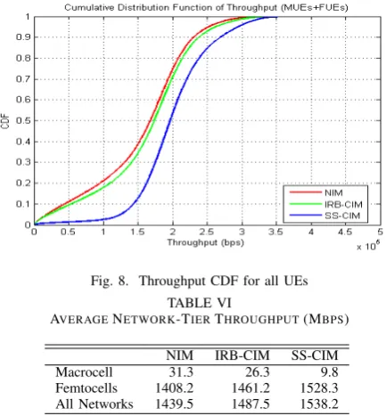
Figure 8 illustrates throughput CDF for macro and femto users. Overall, there is throughput increase for all area when using the proposed method with cell-edges having higher
TABLE IV
AVERAGESUB-CARRIERSINR (DB)
NIM IRB-CIM SS-CIM
Cell-edge (5th-percentile)
Macro UE 0.7 1.7 16.1
Femto UE -4.9 -4.4 14.6
All Users -4.8 -4.3 14.6
All allocated spectrum
Macro UE 20.7 21.6 43.8
Femto UE 31.0 32.5 40.4
TABLE V
AVERAGESUB-CARRIERTHROUGHPUT(KBPS)
NIM IRB-CIM SS-CIM
Cell-edge (5th-percentile)
Macro UE 18.3 21.3 81.1
Femto UE 8.1 9.1 81.0
All Users 8.3 9.3 81.0
All allocated spectrum
Macro UE 104.1 108.6 218.2
Femto UE 156.5 164.0 200.0
All Users 154.8 162.5 200.1
Fig. 7. Throughput CDF for femto-UEs
increase than other region. Table VI shows average throughput of network-tier for three methods in 100-frame transmission. The macrocell throughput for SS-CIM is 68.7% lower than NIM and 62.7% lower than IRB-CIM. However, low average throughput of the macrocell is paid off by higher average throughput in femtocells as much as 8.5% increase over NIM and 4.6% increase over IRB-CIM. For overall systems (a macrocell and femtocells), this method results in average throughput of 6.9% higher than NIM and 3.4% higher than IRB-CIM.
The results expose that there is trade-off between increas-ing overall system performance and decreasincreas-ing macrocell’s throughput. By adjustingγth andϕ, spectrum splitting-based
cognitive interference management can improve femtocells’ and overall system’s performance at the cost of penalizing the macrocell with less spectrum allocation and lower throughput.
VI. CONCLUSION
[image:6.595.317.534.52.286.2]We have proposed a spectrum splitting-based cognitive interference management method which orthogonal spectrums are allocated for different network-tiers. We observed that cross-layer and co-layer interference scenarios have differ-ent characteristic. Orthogonal spectrum allocation-based in-terference management affords to solve these two different interference problems. Based on system level simulation, we showed that the proposed method significantly increased the performance of femtocells and overall system at the cost of penalizing the macrocell’s performance. For femtocells, this method results in average throughput of 8.5% and 4.6% higher than NIM and IRB-CIM, respectively. Whereas, for overall system, the method results in average throughput of 6.9% and 3.4% higher than NIM and IRB-CIM, respectively. However, for the macrocell, this method results in average throughput of
Fig. 8. Throughput CDF for all UEs
TABLE VI
AVERAGENETWORK-TIERTHROUGHPUT(MBPS)
NIM IRB-CIM SS-CIM
Macrocell 31.3 26.3 9.8
Femtocells 1408.2 1461.2 1528.3 All Networks 1439.5 1487.5 1538.2
68.7% and 62.7% lower than NIM and IRB-CIM, respectively. Moreover, the proposed method, which detects control-channel to understand the channel availability, is simpler and faster than IRB-CIM that exchanges information among BSs for the same purpose.
REFERENCES
[1] T. Zahir, K. Arshad, A. Nakata, and K. Moessner, “Interference man-agement in femtocells,” IEEE Communications Surveys & Tutorials, vol.15, no.1, pp. 293-311, First Quarter 2013.
[2] J. G. Andrews, “Interference cancellation for cellular systems: a con-temporary overview,”IEEE Wireless Communications, vol. 12, no. 2, pp. 19–29, April 2005.
[3] K. Stamatiou and J. Proakis, “A performance analysis of coded frequency-hopped OFDMA,” in Proc. of IEEE WCNC, vol. 2, pp. 1132–1137, March 2005.
[4] T. Zahir, K. Arshad, Y. Ko, and K. Moessner, “A downlink power control scheme for interference avoidance in femtocells,” in Proc. of 7th International Wireless Communications and Mobile Computing Conference (IWCMC), pp. 1222–1226, July 2011.
[5] Y. Wu, D. Zhang, H. Jiang, and Y. Wu, “A novel spectrum arrangement scheme for femto cell deployment in LTE macro cells,”in Proc. of IEEE 20th International Symposium on PIMRC, pp. 6–11, Sept 2009. [6] V. Chandrasekhar, J.G. Andrews, Z. Shen, T. Muharemovict, and A.
Gatherer, “Distributed power control in femtocell-underlay cellular net-works,”in Proc. of IEEE GLOBECOM, pp. 1–6, Nov 2009.
[7] M.G. Khoshkholgh, K. Navaie, and H. Yanikomeroglu, “Access strate-gies for spectrum sharing in fading environment: overlay, underlay, and mixed”,IEEE Trans. Mobile Computing, vol. 9, no. 12, pp. 1780–1793, Dec 2010.
[8] S. Haykin, “Cognitive radio: brain-empowered wireless communica-tions,”IEEE JSAC, vol. 23, no. 2, pp. 201–220, Feb 2005.
[9] S. Kaimaletu, R. Krishnan, S. Kalyani, N. Akhtar, and B. Ramamurthi, “Cognitive interference management in heterogeneous femto-macro cell networks,”in Proc. of IEEE ICC, pp. 1–6, 2011.
[10] Z. Kong, Y.-K. Kwok, and J. Wang, “A low-complexity QoS-aware proportional fair multicarrier scheduling algorithm for OFDM systems,”
IEEE Trans. Vehicular Technology, vol. 58, no. 5, pp. 2225 –2235, 2009. [11] 3GPP, “Further advancements for E-UTRA physical layer aspects (Re-lease 9),” Technical Report 3GPP TR 36.814 V9.0.0 (2010-03), 3rd Generation Partnership Project (3GPP), 2010.