“I hereby declare that I have read through this report entitle “Optimal Placement and Sizing of Distributed Generation Considering Costs of Operation Planning” and found that it has comply the partial fulfilment for awarding the degree of Bachelor of Electrical Engineering (Industrial Power).”
Signature :
Supervisor‟s Name : Dr. Aida Fazliana Bt. Abdul Kadir
OPTIMAL PLACEMENT AND SIZING OF DISTRIBUTED GENERATION CONSIDERING COSTS OF OPERATION PLANNING
LOO SOON LII
A report submitted in partial fulfilment of the requirements for the Bachelor of Electrical Engineering (Industrial Power)
Faculty of Electrical Engineering
UNIVERSITI TEKNIKAL MALAYSIA MELAKA
iii
I declare that this report entitles “Optimal Placement and Sizing of Distributed Generation Considering Costs of Operation Planning” is the result of my own research except as cited in the references. The report has not been accepted for any degree and is not concurrently submitted in candidature of any other degree.
Signature :
Name : Loo Soon Lii
iv
Dedicated to my beloved Parents, my siblings
Lecturers and all my friends
v
ACKNOWLEDGEMENT
In the name of God, the most gracious, the most merciful, with the highest praise to God that I manage to complete this final year project successfully without difficulty.
My respected supervisor, Dr. Aida Fazliana Binti Abdul Kadir for the great mentoring that was given to me throughout the project. She has provided guidance, motivation, encouragement, patience and advice during this period.
Last but not least, I would like to thank for my fellow seniors and friends who taught and guide me about the final year project. They have taught me a lot knowledge and have also tried their best to teach me as much as possible to enable me to accomplish this degree project. Their cooperation is greatly appreciated.
vi
ABSTRACT
vii
ABSTRAK
viii
TABLE OF CONTENTS
CHAPTER TITLE PAGE
ACKNOWLEDGEMENT v
ABSTRACT vi
ABSTRAK vii
TABLE OF CONTENTS viii
LIST OF TABLES xi
LIST OF FIGURES xiii
LIST OF ABBREVIATIONS xv
LIST OF APPENDICES xvi
1 INTRODUCTION 1
1.1 Research Background 1
1.2 Problem Statement 2
1.3 Objectives 3
1.4 Scope 3
1.5 Report Organisation 4
2 LITERATURE REVIEW 5
2.1 Introduction 5
ix
2.2.1 Diesel Generators 7
2.2.2 Solar Photovoltaic 8
2.2.3 Wind Power 9
2.2.4 Hydroelectricity 9
2.2.5 Fuel Cells 10
2.3 Benefits of DG 11
2.4 Types of Solar PV Panel 12
2.5 System Cost of Distributed Generation 15
2.6 Review on Optimal Placement and Sizing of DG 16
2.7 Chapter Summary 19
3 METHODOLOGY 20
3.1 Introduction 20
3.2 Problem Formulation 20
3.3 Heuristic Methods 22
3.3.1 Particle Swarm Optimisation (PSO) 22
3.3.2 Gravitational Search Algorithm (GSA) 26
3.3.3 Improved Gravitational Search Algorithm (IGSA) 30 3.4 Application of Heuristic Methods in Costs of Operation
Planning 33
3.5 Test Systems 34
3.6 Costing for Photovoltaic (PV) System 36
3.7 Chapter Summary 37
4 RESULTS AND DISCUSSION 38
x
4.2 IEEE 34-Bus System 38
4.2.1 Optimisation Results 39
4.2.2 Costs of Operation Planning 41
4.3 IEEE 69-Bus System 51
4.3.1 Optimisation Results 51
4.3.2 Costs of Operation Planning 53
4.4 Results Comparison of Test Systems 63
4.5 Chapter Summary 66
5 CONCLUSION AND RECOMMENDATION 67
5.1 Conclusion 67
5.2 Recommendation 68
REFERENCES 69
xi
LIST OF TABLES
TABLE TITLE PAGE
2.1 Characteristics of Monocrystalline, Polycrystalline and Thin-film [14] 13 2.2 Advantages and Disadvantages of Monocrystalline, Polycrystalline
and Thin-film [13] 14
4.1 Optimisation Results from PSO, GSA and IGSA in 34-Bus System 40
4.2 Costs of Power Loss (CL) in 34-Bus System from PSO 41
4.3 Costs of Power Loss (CL) in 34-Bus System from GSA 42
4.4 Costs of Power Loss (CL) in 34-Bus System from IGSA 43
4.5 Costs of Generation (CDG) for MONO PV System in 34-Bus System
from PSO 44
4.6 Costs of Generation (CDG) for MONO PV System in 34-Bus System
from GSA 45
4.7 Costs of Generation (CDG) for MONO PV System in 34-Bus System
from IGSA 46
4.8 Costs of Generation (CDG) for TF PV System in 34-Bus System
from PSO 47
4.9 Costs of Generation (CDG) for TF PV System in 34-Bus System
from GSA 48
4.10 Costs of Generation (CDG) for TF PV System in 34-Bus System
from IGSA 49
4.11 Summary for Costs of Operation Planning (CP) in 34-Bus System 50
4.12 Optimisation Results from PSO, GSA and IGSA in 69-Bus System 52
4.13 Costs of Power Loss (CL) in 69-Bus System from PSO 53
4.14 Costs of Power Loss (CL) in 69-Bus System from GSA 54
xii
4.16 Costs of Generation (CDG) for MONO PV System in 69-Bus System
from PSO 56
4.17 Costs of Generation (CDG) for MONO PV System in 69-Bus System
from GSA 57
4.18 Costs of Generation (CDG) for MONO PV System in 69-Bus System
from IGSA 58
4.19 Costs of Generation (CDG) for TF PV System in 69-Bus System
from PSO 59
4.20 Costs of Generation (CDG) for TF PV System in 69-Bus System
from GSA 60
4.21 Costs of Generation (CDG) for TF PV System in 69-Bus System
from IGSA 61
4.22 Summary for Costs of Operation Planning (CP) in 69-Bus System 62
xiii
LIST OF FIGURES
FIGURE TITLE PAGE
2.1 Integration of Wind DG and PV DG in Distribution System 5
2.2 Criteria for Classification of DG [10] 6
2.3 Standalone Diesel Generator 7
2.4 Grid Connected Solar Farm in Melaka, Malaysia 8
2.5 Wind Power Plant in Xinjiang, China 9
2.6 Itaipu Dam in Brazil 10
2.7 The Operation of Fuel Cell 10
2.8 Average Prices and Sizes of PV Plants by Country in 2010 [17] 15
3.1 Concept of PSO in Search Space [12] 23
3.2 Particle Swarm Optimisation (PSO) Flowchart [11] 25
3.3 Concept of GSA in Search Space 26
3.4 Gravitational Search Algorithm (GSA) Flowchart [28] 29
3.5 Improved Gravitational Search Algorithm (IGSA) Flowchart [6] 32
3.6 Overall Process of the Project 34
3.7 Single Line Diagram of IEEE 34-Bus System [33] 35
3.8 Single Line Diagram of IEEE 69-Bus System [32] 35
3.9 FiT Rates for Solar PV [36] 36
4.1 Convergence Characteristics of PSO, GSA and IGSA for One DG
in 34-Bus System 39
4.2 Convergence Characteristics of the PSO, GSA and IGSA for One DG
in 69-Bus System 51
4.3 Power Losses Before and After Installation of DG in 34-Bus System
xiv
4.4 Correlation between Costs of Operation Planning (CP) and DG Size
in 34-Bus System 65
4.5 Correlation between Costs of Operation Planning (CP) and DG Size
xv
LIST OF ABBREVIATIONS
DG - Distributed Generation
PV - Photovoltaic
Mono - Monocrystalline
Poly - Polycrystalline
TF - Thin-film
PSO - Particle Swarm Optimisation
GSA - Gravitational Search Algorithm
IGSA - Improved Gravitational Search Algorithm
CP - Costs of Operation Planning
CI - Investment Cost
CM - Maintenance Cost
CL - Power Loss Cost
CDG - Generation Cost
IEEE - Institute of Electrical and Electronics Engineers SEDA - Sustainable Energy Department Authority
FiT - Feed-in Tariff
xvi
LIST OF APPENDICES
APPENDIX TITLE PAGE
A Gantt Chart 73
B Bus Data for IEEE 34-Bus System 74
C Branch Data for IEEE 34-Bus System 76
D Bus Data for IEEE 69-Bus System 78
E Branch Data for IEEE 69-Bus System 81
1
CHAPTER 1
INTRODUCTION
1.1 Research Background
In this modern era, electricity demand is increasing due to the economic growth. Increasing in energy consumption can be overcome by promoting the technology of distributed generators in distribution systems using renewable resources. Currently in Malaysia, the main energy resources are from oil and natural gas. By introducing the distributed generation technology, it helps to generate energy more efficient and also reduce environment pollution such as air pollution from the burning of fossil fuels [1].
Typical distribution systems are operating without any generation on the systems. By adding generation at the distribution system, it provides benefits to the power system. DG is a technology that could help to enable efficient, renewable energy production both in developed and developing world. Despite their small size, DG technologies are having a stronger impact in electricity markets [2].
2
By using renewable resources as DG units can be very effective in improving technical, economical and especially environmental characteristics of distribution systems [1]. In Asia, the most suitable renewable resource is solar where photovoltaic (PV) DG is used to generating power from the solar energy such as monocrystalline, polycrystalline and thin-film [3]. To have realistic solutions for DG placement and sizing, the costs of operation planning of the renewable energy-based generating units must be considered so that it can minimise DG’s investment and operating costs and compensating for system losses along the planning period [2].
1.2 Problem Statement
3
1.3 Objectives
The objectives of this study are:
• To determine the optimal placement and sizing of photovoltaic distributed generation.
• To compare the performance of proposed method IGSA with PSO and GSA in terms of fitness value and convergence rate.
• To compare the type of PV DG (Monocrystalline or Thin-film) based on the Costs of Operation Planning (CP).
1.4 Scope
4
1.5 Report Organisation
5
CHAPTER 2
LITERATURE REVIEW
2.1 Introduction
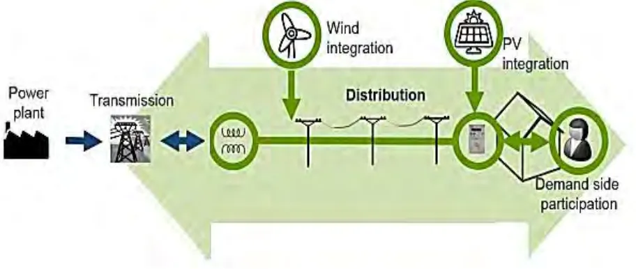
[image:21.612.87.543.444.637.2]Distributed power generation has been developing rapidly in power systems seeing that it is an innovation that could help to produce energy more efficient compare to traditional large generators. DG is a small power generating unit installed at the distribution network or consumer site as a better way for centralized generation. Figure 2.1 shows the integration of renewable DG is at the distribution system, where the generation now is nearer to the load compared to conventional generation.
6
[image:22.612.86.543.216.570.2]DG can produces from less than a kilowatt (kW) to hundreds of megawatts (MW) [2] and it may be grid-connected or work standalone. It is categorized into four sizes based on its capacity. Micro DGs rated between 1 to 5 kW, small DGs rated between 5 kW to 5 MW, medium DGs rated between 5 MW to 50 MW and large DGs rated between 50 MW to 500 MW. Figure 2.2 below shows the criteria for classification of DG [10].
Figure 2.2: Criteria for Classification of DG [10]
Criteria of DG Definition
Point of DG
interconnection Capacity interconnection Purpose of Ownership DG
technology
Transmission network
Distribution
network Renewable renewable
Non-Supply of Active Power
Ancillary services
Micro Small Medium Large Independent power producer Customer owned Utility owned Frequency regulation Voltage regulation Power quality System security Reactive power Reserve requirement
7
2.2 Type of DGs
According to Wichit Krueasuk [11], DGs are classified into 3 types; Type 1 DGs, generate only real power; Type 2 DGs, supplying only reactive power; and Type 3 DGs, supplying real power but absorb reactive power. DGs can based on renewable energy sources such as diesel generators and microturbines; or non-renewable energy sources such as solar photovoltaic, wind power, hydroelectricity and fuel cells [1].
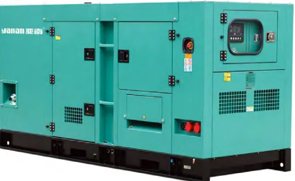
2.2.1 Diesel Generators
[image:23.612.169.458.440.617.2]For standalone operation, diesel generators are most commonly used as it can be started and turn off easily. Microturbines are rapid and mechanically straight forward devices. Currently, its productivity is constantly expanding and its cost is consistently diminishing [1]. But the commonly fuels it used are natural gas and biogas where the emissions from the fuels are not environmental friendly. Figure 2.3 shows the diesel generator that commonly used for standalone operation.
8
2.2.2 Solar Photovoltaic
[image:24.612.135.491.365.605.2]Solar photovoltaic (solar PV) converts sunlight into energy supply. Solar PV uses the inverter technology to connect with the grid. In Thailand, a tropical country like Malaysia has enough of sunshine to generate electricity using the solar PV [12]. Incorporation of solar PV with grid network would help with supplementing the persistently expanding of power requires [12]. For example, Figure 2.4 shows the grid connected solar farm in Melaka, Malaysia. More prominent utilization of PV technology can likewise build unwavering quality of the power network. Solar PV is widely used because it is clean, free and sustainable. However, it is a very expensive technology in the early stage but the cost decrease rapidly due to the highly efficient of this solar energy [1]. The primary disadvantage of solar PV is that their yield power is an element of solar irradiation and temperature which fluctuate always, in this manner, their output power is not fixed at various times [1].
![Figure 2.2: Criteria for Classification of DG [10]](https://thumb-us.123doks.com/thumbv2/123dok_us/133445.12889/22.612.86.543.216.570/figure-criteria-classification-dg.webp)