White Rose Research Online URL for this paper:
http://eprints.whiterose.ac.uk/124712/
Version: Accepted Version
Article:
Hu, Y., Zhu, Z.Q. orcid.org/0000-0001-7175-3307 and Odavic, M. (2017) Torque capability
enhancement of dual three-phase PMSM drive with fifth and seventh current harmonics
injection. IEEE Transactions on Industry Applications, 53 (5). pp. 4526-4535. ISSN
0093-9994
https://doi.org/10.1109/TIA.2017.2707330
© 2017. Personal use of this material is permitted. Permission from IEEE must be obtained
for all other users, including reprinting/ republishing this material for advertising or
promotional purposes, creating new collective works for resale or redistribution to servers
or lists, or reuse of any copyrighted components of this work in other works. Reproduced
in accordance with the publisher's self-archiving policy.
[email protected] https://eprints.whiterose.ac.uk/
Reuse
Items deposited in White Rose Research Online are protected by copyright, with all rights reserved unless indicated otherwise. They may be downloaded and/or printed for private study, or other acts as permitted by national copyright laws. The publisher or other rights holders may allow further reproduction and re-use of the full text version. This is indicated by the licence information on the White Rose Research Online record for the item.
Takedown
If you consider content in White Rose Research Online to be in breach of UK law, please notify us by
Abstract -- A method for enhancing torque capability of a
dual 3-phase permanent magnet synchronous machine (PMSM) based on conventional dual 3-phase drive system by injecting the fifth and seventh current harmonics without any hardware re-configuration is proposed in this paper. Compared with the third current harmonic injection which is commonly used to enhance torque capability of dual three-phase machine, the two isolated neutral points of each set of single 3-phase windings do not need to be re-connected to the middle point of dc-link capacitors or an additional power switching bridge to provide flowing path for zero-sequence current. Further, no additional current sensors are required to obtain the feedback of zero-sequence current to regulate it effectively. For a prototype dual 3-phase PMSM, the average torque increases approximately by 9% at the cost of 0.56% increase in the 12th harmonic torque ripple. The effectiveness of the torque capability enhancement is confirmed by experiments.
Index Terms-- Current harmonics injection, double star
machine, dual three-phase machine, six-phase machine, torque capability, torque enhancement.
I. INTRODUCTION
N some high power industrial applications such as aircraft drives, locomotive traction, electric ship propulsion, etc., both machine and inverter requires high power ratings [1]. However, because of the current rating limitation of power switching devices [2, 3], the inverter rating is limited to a certain range. To solve this issue, a widely acceptable solution is the dual 3-phase machine drive system, which has been a viable approach to obtain high system power rating [4-7] due to its outstanding advantage of the double power capability of the single 3-phase drive system. The typical power topology of the dual 3-phase system is shown in Fig. 1. The dual phase machine is fed by two sets of single 3-phase voltage source inverters(VSIs) [8], where one set is designated as ABC, the other set is designated as XYZ, which is shifted from ABC by 30° electrical degrees.
In previous literature, various methods have been proposed to increase the torque capability of the machine. As proposed in [9-11], one typical approach to increase the torque of PMSMs is to employ the optimal third-harmonic magnet shaping to obtain maximum fundamental flux within the flux limitation. In the same way, the current harmonics
can also be injected to current to obtain the maximum fundamental current within allowed current limit.
A B
C
X Y
Z
6 s
Fig. 1 Dual 3-phase machine drive system [8].
Compared to the single phase counterparts, the dual 3-phase system has the advantage of additional freedom of current harmonics injection, which results in the power and torque capability enhancement [3, 12-14]. For example, the third current harmonics are injected into the stator phase currents to enhance the average torque of a 5-phase induction machine (IM) [13, 15, 16] and PMSM [17]. The third, fifth, and seventh current harmonics are injected into the stator phase currents to enhance the average torque of a 9-phase synchronous reluctance machine [18]. In [19], the third, fifth, seventh, and ninth harmonics injection to the stator currents of an 11-phase IM is proposed to increase the torque capability.
The improvement of torque capability of the dual 3-phase machine by zero-sequence current components (the third current harmonics) injection is introduced in [20, 21]. In order to provide the flowing path for the third current harmonics, the two neutral points of each set of single 3-phase windings in the dual 3-3-phase machine, Fig. 1, have to be re-connected to the middle point of the DC link capacitors or to an additional inverter leg [20, 22]. The proposal of additional inverter leg is particularly essential when the injection of third current harmonic in the midpoint of the DC link capacitors results in undesirable large ripple voltage when operating at low frequency [20]. The undesirable ripple voltage may result in the over-voltage damage of power switching device, the third current harmonics in the DC link capacitors, additional loss, and reduced lifetime.
Normally, to regulate the phase currents (without zero-sequence currents) effectively, two current sensors in each set of single 3-phase windings in dual 3-phase machine are enough when the neutral points are not accessible. However, to regulate the third harmonic current in the zero-sequence currents effectively, each phase winding requires a current sensor to obtain the feedback of zero-sequence currents. Therefore, two additional current sensors and two additional
I
Torque Capability Enhancement of Dual Three-Phase PMSM Drive with Fifth
and Seventh Current Harmonics Injection
Yashan Hu
University of Sheffield Mappin Street, SheffieldS1 3JD, UK [email protected]
Z. Q. Zhu
Fellow, IEEE University of Sheffield Mappin Street, SheffieldS1 3JD, UK [email protected]
Milijana Odavic
Member, IEEE University of Sheffield Mappin Street, Sheffield [image:2.595.312.545.232.310.2]current regulators for third current harmonics injection are required. Although the torque capability of dual 3-phase machine can be increased by the third current harmonic injection, this strategy is not suitable for the dual 3-phase machine without the access to the two isolated neutral points, Fig. 1.
Generally, the fifth and seventh current harmonics in the dual 3-phase machine are suppressed for low current total harmonics distortion (THD). For example, the fifth and seventh current harmonics in the dual 3-phase IM resulting from the inverter non-linearity are suppressed in [23]. The fifth and seventh current harmonics in the dual 3-phase PMSM resulting from the inverter linearity and non-sinusoidal back electromotive force (EMF) are suppressed in [24].
In this paper, the fifth and seventh current harmonics injection in the stator currents are employed to extend the torque capability of the dual 3-phase PMSM. Compared to the strategy of the third current harmonic injection, the prominent advantage of the proposed method is that it can increase the torque capability based on the conventional dual 3-phase drive system without any hardware modification and extra current sensors.
This paper is organized as follows. Firstly, the coefficients of the fifth and seventh current harmonics injection within the same allowed current peak will be determined to obtain the maximum fundamental component. In Section II, the average torque and torque ripple due to the fifth and seventh current harmonics in currents and back EMFs are analyzed in detail. The current control scheme with the fifth and seventh current harmonics injection will be introduced in Section III. Experiments will be conducted on a prototype dual 3-phase PMSM to validate the torque capability improvement in Section IV.
II. FIFTH AND SEVENTH CURRENT HARMONICS INJECTION AND
TORQUE CAPABILITY ENHANCEMENT ANALYSIS
A. Coefficients of Fifth and Seventh Current Harmonics To maximize the magnitude of fundamental current for a given allowed current peak value, the optimal magnitude of
the thirdharmonic is 1/6 of the fundamental component
[9-11], then the magnitude of fundamental can be increased up to 1.15 times. In the same way, the amplitudes and phase angles of the fifth and seventh harmonics can be optimized aiming for the maximum fundamental component for the defined stator current peak value.
The stator current with the fundamental, fifth and seventh harmonics only can be generally expressed as
1 5 5 7 7
( )x i cos( )x i cos(5 x i ) cos(7 x i )
y k k k (1)
where x is the phase angle of the fundamental, i5 and i7 are the displacement angles of the fifth and seventh current harmonics respectively, ki1 is the gain of the fundamental component, ki5 and ki7 are relative gains of the fifth and seventh harmonics to fundamental components respectively. The optimized coefficients are listed in TABLE I, which can be obtained by Matlab Optimization Toolbox or by genetic algorithm [1].
The profile of the optimized current is shown in Fig. 2. It is evident that current peak is within the limit of 1pu, while
the fundamental current peak value is 1.077pu, TABLE I, which means that the fundamental current increases by 7.7% with respect to the stator current without fifth and seventh current harmonics.
TABLE ICOEFFICIENTS OF OPTIMIZATION RESULTS Coefficients Value
ki1 1.077
ki5 -0.126
i5 0
ki7 0.053
i7 0
0 60 120 180 240 300 360
-1.0 -0.5 0.0 0.5
1.0 Combination 5th
fundamental 7th
x ()
Fig. 2 Optimized current with the fifth and seventh harmonics injection.
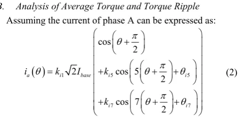
B. Analysis of Average Torque and Torque Ripple Assuming the current of phase A can be expressed as:
1 5 57 7
cos 2
2 cos 5
2
cos 7 2
a i base i i
i i
i k I k
k
(2)
where is the position of permanent magnet (PM) rotor, i5
and i7 are the offset angles of the fifth and seventh current harmonics respectively, ki1 is the gain of the fundamental, ki5 and ki7 are the relative gains of fifth and seventh current harmonics with respect to the fundamental current respectively.
Accounting the fifth and seventh current harmonics in the back EMF, the back EMF of phase A can be expressed as:
1 5 57 7
cos 2
2 5 cos 5
2
7 cos 7
2
a e base e e
e e
e k E k
k
(3)
where e5 and e7 are the offset angles of the fifth and seventh harmonics in back EMF, ke1 is the gain of the fundamental, 5ke5 and 7ke7 are the relative gains of the fifth and seventh harmonics with respect to the fundamental component in back EMF.
Based on (2) and (3), the other phase currents and back EMFs can be expressed as:
4
b Fa s
F (4)
8
c Fa s
F (5)
x Fa s
[image:3.595.310.556.309.429.2] [image:3.595.323.555.526.614.2]
5
y Fa s
F (7)
9
z Fa s
F (8)
where s= /6 and F can be current or back EMF. Neglecting the reluctance torque, the power generated by the first set of single 3-phase windings in dual 3-phase machine (i.e. phases ABC) can be expressed as
1
, ,
phs phs phs a b c
P e i
(9)Substituting (2)-(5) into (9), the torque generated by the phases ABC at rated speed can be expressed as:
1
1 1 1
5 5 7 7
5 5 7 7
5 5 5 5 7 7 7 7
5 7 5 7 7 5 7 5
3
1
5 cos(6 ) 7 cos(6 )
cos(6 ) cos(6 )
5 cos( ) 7 cos( )
5 cos(12 ) 7 cos(12 )
base base e i
rate rate
e e e e
i i i i
e i e i e i e i
e i e i e i e i
P E I
T k k
k k
k k
k k k k
k k k k
(10)
where rate is the rated mechanical speed. The first line in (10) presents the torque generated by the fundamental back EMF and fundamental current. The second line in (10) defines the torque generated by the fifth and seventh back EMF harmonics and fundamental current. The third line in (10) is related to the torque generated by the fundamental back EMF and the fifth and seventh current harmonics. The remaining lines present the torque generated by the interactions of the fifth and seventh harmonics in the current and back EMF.
In the same way, the power generated by the second set of 3-phase windings (i.e. phases XYZ) can be expressed as
2 , , 1 , , phs phs phs x y zphs s phs s s
phs a b c
P e i
e i P
(11)Therefore, the torque generated by the second set of 3-phase windings (i.e. 3-phases XYZ) can be expressed as
2
1
2 1 1
5 5 7 7
5 5 7 7
5 5 5 5 7 7 7 7
5 7 5 7 7 5 7 5
3
1
5 cos(6 ) 7 cos(6 )
cos(6 ) cos(6 )
5 cos( ) 7 cos( )
5 cos(12 ) 7 cos(12 )
s base base e i
rate rate rate
e e e e
i i i i
e i e i e i e i
e i e i e i e i
P P E I
T k k
k k
k k
k k k k
k k k k
(12)
Combining (10) and (12), the total power and torque generated by both sets (phase ABC and XYZ) will be (13) and (14) respectively.
1
2
, , , , ,
phs phs phs a b c x y z
P e i P P
(13)
1 15 5 5 5 7 7 7 7
5 7 5 7 7 5 7 5
6
1
5 cos( ) 7 cos( )
5 cos(12 ) 7 cos(12 )
base base e i
rate rate
e i e i e i e i
e i e i e i e i
P E I
T k k
k k k k
k k k k
(14)
From (10) and (12), it can be concluded that the sixth harmonic in the torque generated by each set has the same amplitude, but they are anti-phase. Therefore, there is no sixth harmonic in the total torque, as shown in (14), even when there are fifth and seventh harmonics in the current or back EMF. If there are no fifth and seventh harmonics in the back EMF, it can be deduced from (14) that the average torque increases by 7.7% without any 6th harmonic torque ripple.
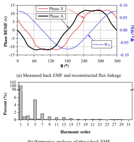
For the prototype dual 3-phase PMSM defined in TABLE
IV, the measured back EMF and the reconstructed flux linkage with respect to the rotor position are shown in Fig. 3(a). Assuming the measured back EMF of phase A with respect to can be expressed in a Fourier series as
0 1
cos
2
a n en
n
e A A n
(15)where A0 is the DC component, An and en is the amplitude
and offset angle of the nth harmonic respectively. The
harmonic analyses of the measured back EMF is listed in TABLE II. From the harmonic analyses shown in Fig. 3(b)
and TABLE II, it is obvious that the third, fifth and seventh harmonics are dominant in the back EMF.
0 60 120 180 240 300 360
-15 -10 -5 0 5 10 15 Phase A Phase X Ph a se B E M F ( v ) () -0.10 -0.05 0.00 0.05 0.10 A A (Wb)
(a) Measured back EMF and reconstructed flux linkage
1 3 5 7 9 11 13 15 17 19 21 23 25 27 29 31 0 2 4 6 98 100 102 Pe rc en t (% ) Harmonic order
[image:4.595.46.291.68.304.2](b) Harmonics analyses of phase back EMF Fig. 3 Measured back EMF and harmonic analyses.
[image:4.595.318.545.415.656.2]EMF in (3) can be obtained from TABLE II and listed in
TABLE III.
According to (14), the torque of the prototype dual-three phase PMSM can be rewritten as (16) when the optimized current in Fig. 2 are injected into the stator currents.
/
6 / 1.086 0.00563 cos(12 3.18)
rate
base base rate
T P
E I
(16)
TABLE IIFOURIER ANALYSIS OF PHASE BACK EMF Harmonic order (n) An (V) An(pu) en(rad)
0 0.009838 0.000765 3.141985
1 12.864000 1.000000 0
2 0.137000 0.011000 5.708
3 0.636000 0.049000 3.118
4 0.039000 0.003060 2.913815
5 0.816000 0.063000 3.217815
6 0.020000 0.001578 2.924815
7 0.189000 0.015000 6.261815
8 0.007011 0.000545 5.949815
9 0.132000 0.010000 2.774629
10 0.013000 0.000997 2.395629
11 0.093000 0.007244 3.332629
TABLE IIICOEFFICIENTS OF PHASE BACK-EMF Coefficient Value
ke1 1
ke5 0.063/5
e5 3.218
ke7 0.015/7
e7 6.262
From (16), it can be concluded that the average torque capability can be enhanced by 8.6% for the prototype dual 3-phase PMSM with the fifth and seventh current harmonics injection, while the 12th harmonic torque ripple is only 0.56% , which is negligible.
[image:5.595.42.288.169.390.2]For a new prototype machine, the torque enhancement can be evaluated by (14) if the back-EMF is known by measurement. The evaluation procedure can be summarized in Fig. 4.
Fig. 4 Procedure of torque enhancement evaluation.
It is worth noting that although the average torque is improved by 8.6% by the fifth and seventh current harmonics
injection, the root mean square (RMS) current is also increased approximately by 8.6%, which leads to the increased copper losses of the machine. However, the ratio of torque to RMS current is almost the same to that without fifth and seventh current harmonics injection. Therefore, under the same torque condition, the copper loss with and without fifth and seventh current harmonics are the same. However, due to the different fundamental current and fifth and seventh current harmonics in these two cases, their iron losses are slightly different which needs to be verified by experiments.
III.CONTROL SCHEME OF CURRENT HARMONICS INJECTION
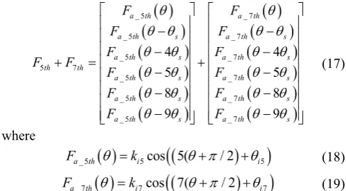
Based on the vector space decomposition (VSD) control for the dual 3-phase machine [25], which is briefly introduced in APPENDIX A, By the matrix transformation in (25), all the fifth and seventh current harmonics are mapped to z1z2 sub-plane. Therefore, the fifth and seventh current harmonics injection to the stator currents can be implemented by injecting the fifth and seventh current harmonics in the z1z2 sub-plane.
Assuming the fifth and seventh current harmonics in the phase currents can be expressed as:
_ 5 _ 7
_ 5 _ 7
_ 5 _ 7
5 7
_ 5 _ 7
_ 5 _ 7
_ 5 _ 7
4 4
5 5
8 8
9 9
a th a th
a th s a th s
a th s a th s
th th
a th s a th s
a th s a th s
a th s a th s
F F
F F
F F
F F
F F
F F
F F
(17)
where
_ 5 5cos 5( / 2 5
a th i i
F k (18)
_ 7 7cos 7( / 2 7
a th i i
F k (19)
By applying the Clark transformation to the fifth and seventh current harmonics in each set of 3-phase windings and then followed by Park transformation, the fifth and seventh current harmonics is converted to sixth harmonics in d-axis and q-axis for each set in dq-frame.
2 _ 6 1_ 6 5 5 7 7
2 _ 6 1_ 6 5 5 7 7
sin(6 ) sin(6 )
cos(6 ) cos(6 )
d th d th i i i i
q th q th i i i i
F F k k
F F k k
(20)
where Fd1_6thand Fq1_6th denote the sixth harmonics in d-axis
and q-axis components for phases ABC. The Fd2_6thand
Fq2_6th denote the sixth harmonics in d-axis and q-axis components for phases XYZ. From (20) it can be observed that the fifth and seventh current harmonics in the real frame for phases ABC and XYZ are represented in the dq frame by the sixth-harmonic components that have the same amplitude but are out of phase.
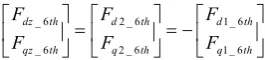
By applying matrix (26) to (17), the fifth and seventh harmonics are projected to the z1z2 sub-plane [25], and then by applying (27) to the components in z1z2 sub-plane, the fifth and seventh harmonics are converted to the sixth
harmonics in dqz-frame, which have the following
[image:5.595.305.555.332.470.2] [image:5.595.119.222.515.692.2]_ 6 2 _ 6 1 _ 6
_ 6 2 _ 6 1 _ 6
dz th d th d th
qz th q th q th
F F F
F F F
(21)
(21) indicates that the sixth current harmonics in each set of single 3-phase windings can be regulated simultaneously by regulating the sixth current harmonics in the dqz-frame. Consequently, the fifth and seventh current harmonics in each phase can be regulated effectively.
The current control scheme is shown in Fig. 5. The phase currents ia, ib, ic, ix, iy, and iz in the real frame are mapped to
sub-plane and z1z2 sub-plane by applying conversion
matrix [T6] in Appendix A. Through the Park conversion, the components in sub-plane are converted to id and iq in dq -frame. The components in z1z2 sub-plane are converted to idz and iqz in dqz-frame by applying [Tdqz]. The currents are controlled in dq-frameand in dqz-frameseparately.
* d
i
* q
i
, , a b c
i i i
, , x y z
i i i
6 [ ]T 1 z
i
2 z
i
q
i
* d
U
* q
U
i i
d i
*
U
*
U
* 2 z U
* 1 z
U
* 1 0
o
U
* 2 0
o
U
i i
qz
idz
i
1 z
i
2 z
i
dqz T
1 dqz
T
abc
v
xyz
v
1 6
[ ]T
1
Z
2
Z
2 2
6
i K s s
2 2
6
i K s s
dz
i
qz
i
dz
F
qz
F
5 7
, i , i
5 i
k
7 i
k
* q
i
1 o
i
2 o
[image:6.595.96.229.57.87.2]i
Fig. 5 Current control based on VSD with fifth and seventh harmonics injection.
In this control scheme, a conventional proportional and integral (PI) controllers and a resonant controllers [26-28] are employed to regulate the DC components and sixth
harmonics in idz and iqz in dqz-frame. The reference
commands for dqz-frame can be obtained by (20) and (21). It is worth noting that the resonance control is usually implemented by replacing the ideal integrator with an approximated low-pass filter transfer function in practice [27]. The cut-off frequency of the low-pass filter and the integral gain of resonant controller are very important considering the stability [27]. In this paper, the cut-off frequency is chosen as 1/200 times of the resonance frequency (6 ), the integral gain of the resonant controller is chosen to be the same as the integral gain in the PI controller
in dqz-frame. Usually, the resonant controllers may have
stability issue when the fundamental frequency increases. However, if the sixth harmonic frequency is far less than the execution rate of the current loop, then the control capability of the resonant controller can be guaranteed. Another limitation of the proposed method is that the injected fifth
and seventh current harmonics may increase fifth and seventh voltage harmonics, which may result in the output voltage hitting the output voltage limit and consequently reduced DC bus utilization especially in flux-weakening region.
IV.EXPERIMENTS
To evaluate the effectiveness of the proposed method, the hardware platform is constructed based on DSPACE DS1005. The experimental setup is illustrated in Fig. 6. The power inverter topology is the same as Fig. 1. Two independent single 3-phase SVPWM modulators are employed to generate PWM duties for each set. The execution rate of the current loop is configured to be 10 kHz, which is the same as the PWM frequency. The design parameters of the prototype dual 3-phase PMSM are shown in TABLE IV.
In these experiments, the machine is coupled to a PM DC machine, which is connected with an adjustable power resistor used as adjustable load. Neglecting the friction, the power generated by the prototype machine and consumed by the load machine has the following relationship
2 2
L e
L L
E T
p R R
(22)
[image:6.595.50.283.248.483.2]where Te is the torque generated by the prototype machine, is the electrical speed, p is the pole pair number of prototype machine, RL is the sum of the adjustable power resistor and the stator resistor of the load machine, EL is the back EMF generated by the PM DC load machine.
Fig. 6 Experimental setup for dual 3-phase PMSM drive test rig
Since EL is proportional to for the PM DC load machine, it can be deduced from (22) that Te is proportional to the electrical speed.
e
T (23)
Consequently, the electrical speed can be used to indicate the torque generated by the prototype dual 3-phase PMSM machine.
TABLE IV
DESIGN PARAMETERS OF PROTOTYPE DUAL THREE-PHASE PMSM
Parameters Value Resistance ( ) 1.096 Leakage inductance (mH) 0.875
d-axis self-inductance (mH) 2.141
q-axis self-inductance (mH) 2.141 No load permanent magnet flux linkage (Wb) 0.075
Pole pairs 5
Rated power (W) 240
DC link voltage(V) 40
[image:6.595.307.552.413.496.2]and seventh current harmonics injection in this section. The first is the comparison of current control with the same fundamental. The second is the comparison of at same speed. The third is the comparison of current control with same peak current. Afterwards, the torque enhancement with third harmonic injection will be introduced.
A. Same Fundamental Current with and without Fifth and Seventh Harmonic Injection
In this experiment, the drive works in constant current control mode, the iq and id current references are 1.5A and 0A respectively.
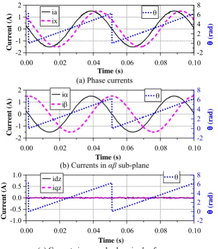
The phase currents without fifth and seventh current
harmonics are shown in Fig. 7(a). The currents in
sub-plane are shown in Fig. 7(b) and the currents in z1z2 sub-plane in dqz-frame are shown in Fig. 7(c), which shows that the fifth and seventh current harmonics are regulated to zero fairly well.
0.00 0.02 0.04 0.06 0.08 0.10 -2 -1 0 1 2 ia ix Cu rr en t ( A ) -2 0 2 4 6 8 Time (s) (r a d )
(a) Phase currents
0.00 0.02 0.04 0.06 0.08 0.10 -2 -1 0 1 2 Time (s) i i Cur rent (A) -2 0 2 4 6 8 (rad)
(b) Currents in sub-plane
0.00 0.02 0.04 0.06 0.08 0.10 -1.0 -0.5 0.0 0.5 1.0 Time (s) idz iqz Cu rre n t ( A ) -2 0 2 4 6 8 (r a d )
[image:7.595.325.548.78.334.2](c) Currents in z1z2 sub-plane in dqz-frame
Fig. 7 Measured currents without fifth and seventh current harmonics injection
The phase currents with fifth and seventh current harmonics are shown in Fig. 8(a), where the phase currents have the same shape to that shown in Fig. 2. The currents in sub-plane are shown in Fig. 8(b) and the currents in z1z2 sub-plane in dqz-frame are shown in Fig. 8(c), which shows that the fifth and seventh current harmonics are converted to 6th harmonics in dqz-frame.
The currents of phase A and X and their corresponding harmonics analyses with and without the fifth and seventh current harmonics are shown in Fig. 9(a) and Fig. 9(b) respectively. As shown in Fig. 9(b), it is evident that there are no fifth and seventh current harmonics in the spectrum without current harmonics injection, while there are specific fifth and seventh current harmonics in the spectrum with current harmonics injection. The fundamental currents with and without current harmonics injection are the same. However, the current peak value with current harmonics
injection is obviously reduced compared with that without current harmonics injection [see Fig. 9(a)].
0.00 0.02 0.04 0.06 0.08 0.10 -2 -1 0 1 2 ia ix Cu rr en t ( A ) -2 0 2 4 6 8 Time (s) e e ( rad)
(a) Phase currents
0.00 0.02 0.04 0.06 0.08 0.10 -2 -1 0 1 2 Time (s) i i Cur rent (A) -2 0 2 4 6 8 e e (r ad )
(b) Currents in sub-plane
0.00 0.02 0.04 0.06 0.08 0.10 -1.0 -0.5 0.0 0.5 1.0 Time (s) idz iqz Cu rre n t ( A ) -2 0 2 4 6 8 e e ( rad)
[image:7.595.65.286.260.513.2](c) Currents in z1z2 sub-plane in dqz-frame
Fig. 8 Measured currents with fifth and seventh current harmonics injection
0 30 60 90 120 150 180 210 240 270 300 330 360 -2
-1 0 1 2
ia @ w/o injection ix @ w/o injection ia @ w/ injection ix @ w/ injection
Cu rre n t ( A) ()
(a) Phase currents
1 3 5 7 9 11 13 15 17
0.0 0.5 1.0 1.5 2.0 C u rr en t (A) Harmonic order
ia @ w/o injection ia @ w/ injection
3 5 7 9 11 13 15 17 0.0 0.1 0.2 Curr ent (A) Harmonic order
(b) Harmonics analyses of phase current
0.0 0.1 0.2 0.3 0.4
100 150 200 250 300 Average:246
speed @ w/o injection speed @ w/ injection
Spe
ed (rpm)
Time (s)
Average:242
(c) Speed
[image:7.595.319.543.361.729.2]The average speeds with and without current harmonics injection are shown in Fig. 9(c). It shows that the average speeds are slightly different in these two cases since there is additional torque generated by the fifth and seventh harmonics in the current and back EMF, i.e. the second part of (14). The additional average torque with the fifth and seventh current harmonics injection will be approximately 0.87% of the torque generated by fundamental current and back EMF.
B. Same Speed with and without Fifth and Seventh Harmonic Injection
In this experiment, the drive works in constant speed mode, the speed reference is 250 rpm. The phase currents versus time with and without fifth and seventh current harmonics are similar to that in Fig. 7 and Fig. 8; therefore, they are not repeated here for simplicity. The phase current profiles versus rotor position and corresponding harmonic analyses with and without fifth and seventh current harmonics injection are shown in Fig. 10(a) and (b) respectively. The speed feedback with and without injection are shown in Fig. 10(c). It shows that the feedback speed are the same in these two cases, which indicates the average torque with and without injection are the same.
0 30 60 90 120 150 180 210 240 270 300 330 360 -2
-1 0 1 2
ia @ w/o injection ix @ w/o injection ia @ w/ injection ix @ w/ injection
Cu
rre
n
t (
A)
()
(a) Phase currents
1 3 5 7 9 11 13 15 17
0.0 0.5 1.0 1.5 2.0
C
u
rr
en
t (A)
Harmonic order
ia @ w/o injection ia @ w/ injection
3 5 7 9 11 13 15 17 0.0
0.1 0.2 0.3
Curr
ent
(A)
Harmonic order
(b) Harmonics analyses of phase current
0.0 0.1 0.2 0.3 0.4
150 200 250 300 350
speed @ w/o injection speed @ w/ injection
Spe
ed (rpm)
Time (s)
(c) Speed
Fig. 10 Comparison at same speed with/without fifth and seventh harmonic injection
It is worth noting that the fundamental current with current harmonic injection is slightly lower than that without current harmonic injection in Fig. 10(b), which is due to the additional torque generated by the fifth and seventh harmonics in current and back EMF. As shown in Fig. 10(a), it is obvious that the current peak value without current harmonics injection is higher than that with current harmonics injection. It can be concluded that the peak current with fifth and seventh current harmonics injection is reduced significantly while keeping the same torque capability.
C. Same Current Peak with and Without Fifth and Seventh Harmonic Injection
In this experiment, the drive works in constant current mode, the iq current reference is 1.5A for the current control without current harmonics injection. To maintain the same current peak for the current control with current harmonics
injection, the iq current reference is 1.5A*1.077=1.615A
according to TABLE I.
0 30 60 90 120 150 180 210 240 270 300 330 360 -2
-1 0 1 2
ia @ w/o injection ix @ w/o injection ia @ w/ injection ix @ w/ injection
Cu
rre
n
t (
A)
()
(a) Phase currents
1 3 5 7 9 11 13 15 17
0.0 0.5 1.0 1.5 2.0
C
u
rr
en
t (A)
Harmonic order
ia @ w/o injection ia @ w/ injection
3 5 7 9 11 13 15 17 0.0
0.1 0.2 0.3
Curr
ent
(A)
Harmonic order
(b) Harmonics analyses of phase current
0.0 0.1 0.2 0.3 0.4
100 150 200 250 300
Average:264
speed @ w/o injection speed @ w/ injection
Spe
ed (rpm)
Time (s)
Average:242
[image:8.595.321.546.281.652.2](c) Speed
Fig. 11 Comparison of same peak current with/without fifth and seventh harmonics.
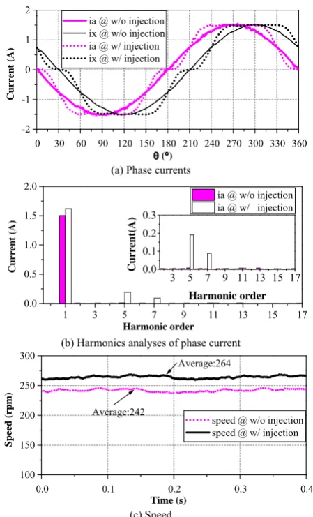
[image:8.595.59.281.346.714.2]harmonic analyses in Fig. 11(b), the fundamental current with current harmonics injection is obviously higher than that without current harmonics injection. Meanwhile, the average speed with harmonics injection is significantly higher than that without harmonics injection, as can be seen from Fig. 11(c).
As indicated in (23), the ratio of the torque with current harmonic injection divided by the torque without current harmonic injection can be reflected by the speed ratio.
_ _
264 1.09 242
e with with
e without without
T rpm
T rpm (24)
(24) shows that the torque capability is increased by 9% within the same current limit by the fifth and seventh current harmonics injection, which is in accordance with (16).
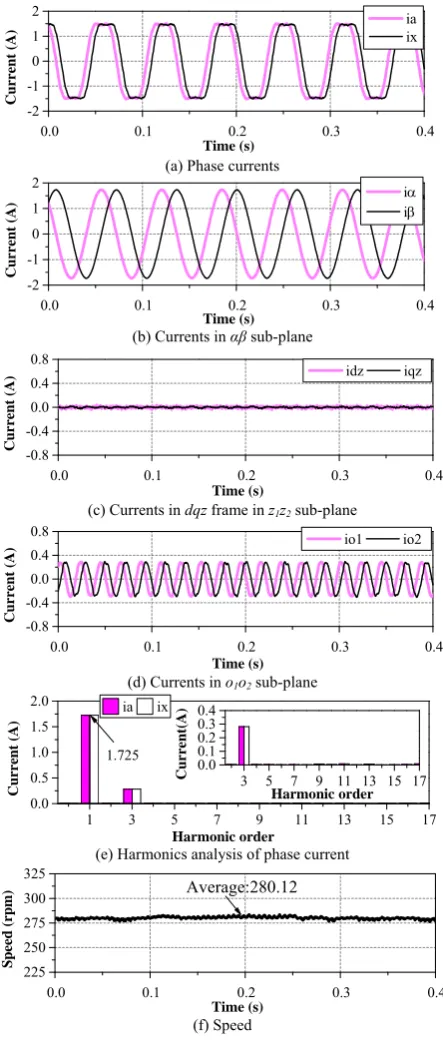
D. Same Current Peak with Third Harmonic Injection In this experiment, to provide the flowing path for the third harmonic currents, the neutral points in the dual 3-phase machine are connected to the mid-point of the DC bus. As can be seen from Fig. 12, the peak current is regulated to 1.5A [Fig. 12(a)], which is the same as the peak current in
Fig. 11. As the optimal magnitude of the thirdharmonic is
1/6 of the fundamental component [9-11], the magnitude of fundamental can be increased up to 1.15 times of 1.5A, that is 1.5A*1.15 = 1.725A [Fig. 12(e)]. The fifth and seventh
harmonics are regulated to zero [Fig. 12(c)]; the
zero-sequence currents are shown in Fig. 12 (d).
The average speed is 280.12rpm. Compared to the speed without harmonics injection in Fig. 11(c), the speed ratio will be 280.12/242 = 1.158, which means the torque ratio is also 1.158 according to (23).
Compared to the torque improvement by fifth and seventh current harmonics injection, the third harmonic injection can increase the torque further. However, as detailed in the introduction part, the strategy of third harmonic injection needs the access of the neutral points, it also needs more current sensors and more current regulators, and it suffers the mid-point DC bus voltage variation, etc.
V. CONCLUSION
This paper proposes a method of the fifth and seventh current harmonics injection to enhance torque capability of a dual 3-phase PMSM drive system within the same current limit. This method is based on the conventional dual 3-phase inverter and does not need any hardware modification and extra current sensors compared to the method of third current harmonic injection. This method could be a useful alternative if additional torque is required and the current already reaches its limit. The torque capability of dual 3-phase PMSM can be improved by 7.7% without the12th order torque ripple if there is no fifth and seventh harmonics in back EMF, while the average torque is increased by about 8.6% at the cost of negligible 0.56% 12th order torque ripple for the prototype dual 3-phase PMSM. Experiments have been conducted on the prototype machine to validate the enhancement of the torque capability.
0.0 0.1 0.2 0.3 0.4
-2 -1 0 1 2
ia ix
Cu
rren
t (A
)
Time (s)
(a) Phase currents
0.0 0.1 0.2 0.3 0.4
-2 -1 0 1 2
i i
C
u
rr
en
t (A)
Time (s)
(b) Currents in sub-plane
0.0 0.1 0.2 0.3 0.4
-0.8 -0.4 0.0 0.4 0.8
idz iqz
Cu
rr
en
t (A
)
Time (s)
(c) Currents in dqz frame in z1z2 sub-plane
0.0 0.1 0.2 0.3 0.4
-0.8 -0.4 0.0 0.4 0.8
io1 io2
C
u
rr
en
t (A)
Time (s)
(d) Currents in o1o2 sub-plane
1 3 5 7 9 11 13 15 17
0.0 0.5 1.0 1.5
2.0 ia ix
C
u
rr
ent (A
)
Harmonic order
1.725
3 5 7 9 11 13 15 17 0.0
0.1 0.2 0.3 0.4
C
u
rr
en
t(
A)
Harmonic order
(e) Harmonics analysis of phase current
0.0 0.1 0.2 0.3 0.4
225 250 275 300 325
Spe
ed
(r
pm)
Time (s)
Average:280.12
[image:9.595.318.540.56.577.2](f) Speed
Fig. 12 Experiment with third current harmonics injection (Peak value:1.5A)
VI.APPENDIX A
According to VSD theory [25], the original six-dimensional machine system can be decomposed into three orthogonal sub-spaces, i.e. , z1z2, o1o2sub-planes. Different harmonics are mapped to different sub-planes. The fundamental and (12k±1)th, k (1, 2, 3…) harmonics in real
frame are mapped to sub-plane; the (6k±1)th, k (1, 3,
1 2 1 2
6
T
z z o o
T
a x b y c z
F F F F F F
T F F F F F F
(25)
where the transformation matrix [T6] is shown in (26)
61 cos( ) cos(4 ) cos(5 ) cos(8 ) cos(9 )
0 sin( ) sin(4 ) sin(5 ) sin(8 ) sin(9 )
1 cos(5 ) cos(8 ) cos( ) cos(4 ) cos(9 )
1
0 sin(5 ) sin(8 ) sin( ) sin(4 ) sin(9 )
3
1 0 1 0 1 0
0 1 0 1 0 1
s s s s s
s s s s s
s s s s s
s s s s s
T
(26)
where s = /6. Define [Tdqz] as (27) and matrix
transformation as (28) [24].
-cos sin
sin cos
dqz
T
(27)
1 2
dz z
dqz
qz z
F F
T
F F
(28)
where F is v, i, or , which are corresponding with phase voltage, current, and stator flux-linkage respectively. By this matrix transformation, the variables in z1z2 sub-plane are
mapped to a new frame, which is designated as dqz-frame.
Consequently, all the (6k±1)th, k (1, 3, 5…) harmonics in z1z2 sub-plane are converted to (6k)th harmonics in dqz -frame.
REFERENCE
[1] A. S. Abdel-Khalik, S. Mostafa Gadoue, M. I. Masoud, and B. W. Wiliams, "Optimum flux distribution with harmonic injection for a multiphase induction machine using genetic algorithms," IEEE Trans. Energy Convers., vol. 26, no. 2, pp. 501-512, 2011.
[2] K. Gopakumar, S. Sathiakumar, S. K. Biswas, and J. Vithayathil, "Modified current source inverter fed induction motor drive with reduced torque pulsations," IEE Proc. B Elect. Power Appl., vol. 131, no. 4, pp. 159-164, 1984.
[3] E. Levi, "Multiphase electric machines for variable-speed applications," IEEE Trans. Ind. Electron., vol. 55, no. 5, pp. 1893-1909, 2008.
[4] R. Hyung-Min, K. Jang-Hwan, and S. Seung-Ki, "Analysis of multiphase space vector pulse-width modulation based on multiple d-q spaces concept," IEEE Trans. Power Electron., vol. 20, no. 6, pp. 1364-1371, 2005.
[5] J. W. Kelly, E. G. Strangas, and J. M. Miller, "Multiphase space vector pulse width modulation," IEEE Trans. Energy Convers., vol. 18, no. 2, pp. 259-264, 2003.
[6] F. Barrero and M. J. Duran, "Recent advances in the design, modeling, and control of multiphase machines-Part I," IEEE Trans. Ind. Electron., vol. 63, no. 1, pp. 449-458, 2016.
[7] M. J. Duran and F. Barrero, "Recent advances in the design, modeling, and control of multiphase machines-Part II," IEEE Trans. Ind. Electron., vol. 63, no. 1, pp. 459-468, 2016.
[8] K. Gopakumar, V. T. Ranganthan, and S. R. Bhat, "Split-phase induction motor operation from PWM voltage source inverter," IEEE Trans. Ind. Appl., vol. 29, no. 5, pp. 927-932, 1993.
[9] Z. Q. Zhu, K. Wang, and G. Ombach, "Optimal magnet shaping with third order harmonic for maximum torque in brushless AC machines," in Proc. 6th IET Int. Conf. Power Electron., Mach. Drives, 2012, pp. 1-6.
[10] K. Wang, Z. Q. Zhu, G. Ombach, and W. Chlebosz, "Average torque improvement of interior permanent-magnet machine using third harmonic in rotor shape," IEEE Trans. Ind. Electron., vol. 61, no. 9, pp. 5047-5057, 2014.
[11] K. Wang, Z. Q. Zhu, and G. Ombach, "Torque enhancement of surface-mounted permanent magnet machine using third-order harmonic," IEEE Trans. Magn., vol. 50, no. 3, pp. 104-113, 2014. [12] Y. Hu, Z. Q. Zhu, and M. Odavic, "Torque capability enhancement of
dual three-phase PMSM drive with fifth and seventh current harmonics injection," in Proc. XXII Int'l Conf. on Electr. Mach.(ICEM), 2016, pp. 599-605.
[13] M. J. Duran, F. Salas, and M. R. Arahal, "Bifurcation analysis of five-phase induction motor drives with third harmonic injection," IEEE Trans. Ind. Electron., vol. 55, no. 5, pp. 2006-2014, 2008.
[14] A. S. Abdel-Khalik, M. I. Masoud, S. Ahmed, and A. M. Massoud, "Effect of current harmonic injection on constant rotor volume multiphase induction machine stators: A comparative study," IEEE Trans. Ind. Appl., vol. 48, no. 6, pp. 2002-2013, 2012.
[15] H. Xu, H. A. Toliyat, and L. J. Petersen, "Rotor field oriented control of five-phase induction motor with the combined fundamental and third harmonic currents," in Proc. 16th Annu. IEEE Appl. Power Electron. Conf. Expo., 2001, pp. 392-398 vol.1.
[16] H. Xu, H. A. Toliyat, and L. J. Petersen, "Five-phase induction motor drives with DSP-based control system," IEEE Trans. Power Electron.,
vol. 17, no. 4, pp. 524-533, 2002.
[17] L. Parsa and H. A. Toliyat, "Five-phase permanent-magnet motor drives," IEEE Trans. Ind. Appl., vol. 41, no. 1, pp. 30-37, 2005. [18] C. Coates, D. Platt, and V. J. Gosbell, "Performance evaluation of a
nine-phase synchronous reluctance drive," in Proc. 36th IAS Annu. Meeting Ind. Appl. Conf., 2001, pp. 2041-2047 vol.3.
[19] A. Abdelkhalik, M. Masoud, and W. Barry, "Eleven-phase induction machine: steady-state analysis and performance evaluation with harmonic injection," IET Electr. Power Appl., vol. 4, no. 8, pp. 670-685, 2010.
[20] R. O. C. Lyra and T. A. Lipo, "Torque density improvement in a six-phase induction motor with third harmonic current injection," IEEE Trans. Ind. Appl., vol. 38, no. 5, pp. 1351-1360, 2002.
[21] K. Wang, Z. Q. Zhu, Y. Ren, and G. Ombach, "Torque improvement of dual three-phase permanent-magnet machine with third-harmonic current injection," IEEE Trans. Ind. Electron., vol. 62, no. 11, pp. 6833-6844, 2015.
[22] F. B. Bendixen, F. Blaabjerg, P. O. Rasmussen, P. Vadstrup, and K. Krabbe, "Controlling the DC-link midpoint potential in a six-phase motor-drive," in Proc. IEEE 35th Annu. Power Electron. Spec. Conf., 2004, pp. 2128-2132 Vol.3.
[23] H. S. Che, E. Levi, M. Jones, W. P. Hew, and N. A. Rahim, "Current control methods for an asymmetrical six-phase induction motor drive,"
IEEE Trans. Power Electron., vol. 29, no. 1, pp. 407-417, 2014. [24] Y. Hu, Z. Q. Zhu, and K. Liu, "Current control for dual three-phase PM
synchronous motors accounting for current unbalance and harmonics,"
IEEE J. Emerg. Sel. Topics Power Electron., vol. 2, no. 2, pp. 272-284, 2014.
[25] Y. Zhao and T. A. Lipo, "Space vector PWM control of dual three-phase induction machine using vector space decomposition," IEEE Trans. Ind. Appl., vol. 31, no. 5, pp. 1100-1109, 1995.
[26] D. N. Zmood, D. G. Holmes, and G. H. Bode, "Frequency-domain analysis of three-phase linear current regulators," IEEE Trans. Ind. Appl., vol. 37, no. 2, pp. 601-610, 2001.
[27] D. N. Zmood and D. G. Holmes, "Stationary frame current regulation of PWM inverters with zero steady-state error," IEEE Trans. Power Electron., vol. 18, no. 3, pp. 814-822, 2003.
Yashan Hu received the B.Eng. and M.Sc. degrees in Electronic and Electrical Engineering from the Northwestern Polytechnical University, Xi’an, China, in 2002 and 2005, respectively. He has been working toward the Ph.D. degree at the University of Sheffield, Sheffield, U.K., since Jun 2012.
From 2005 to 2012, he was with Delta Green Tech (China) Co., Ltd., Shanghai, China, Shanghai Yungtay Elevator Co. Ltd as a Research Engineer, and Shanghai Welling Motor R&D Centre as Project Manager. His research interests are control of electric drives.
Z. Q. Zhu (M’90–SM’00–F’09) received the B.Eng. and M.Sc. degrees from Zhejiang University, Hangzhou, China, in 1982 and 1984, respectively, and the Ph.D. degree from the University of ShefÞeld, ShefÞeld, U.K., in 1991, all in electrical engineering.
From 1984 to 1988, he lectured in the Department of Electrical Engineering, Zhejiang University. Since 1988, he has been with the University of ShefÞeld, where since 2000, he has been a Professor of electrical machines and control systems in the Department of Electronic and Electrical Engineering, and is currently the Head of the Electrical Machines and Drives Research Group. His current major research interests include the design and control of permanent-magnet brushless machines and drives for applications ranging from automotive to renewable energy.
Milijana Odavic (M’13) received the M.Sc. degree in electrical and electronic engineering from the University of Zagreb, Zagreb, Croatia, in 2004 and the Ph.D. degree from the University of Nottingham, Nottingham, U.K., in 2008.
![Fig. 1 Dual 3-phase machine drive system [8].](https://thumb-us.123doks.com/thumbv2/123dok_us/7757767.169101/2.595.312.545.232.310/fig-dual-phase-machine-drive-system.webp)