This is a repository copy of
Frequency Selective Surface Loaded Antenna for Direct
Antenna Modulation
.
White Rose Research Online URL for this paper:
http://eprints.whiterose.ac.uk/121845/
Version: Accepted Version
Proceedings Paper:
Henthorn, S., Ford, K.L. orcid.org/0000-0002-1080-6193 and O'Farrell, T.
orcid.org/0000-0002-7870-4097 (2017) Frequency Selective Surface Loaded Antenna for
Direct Antenna Modulation. In: 2017 11th European Conference on Antennas and
Propagation (EUCAP). 2017 11th European Conference on Antennas and Propagation
(EUCAP), 19-24 March 2017, Paris, France. IEEE , pp. 731-734.
10.23919/EuCAP.2017.7928325
© 2017 IEEE. Personal use of this material is permitted. Permission from IEEE must be
obtained for all other users, including reprinting/ republishing this material for advertising or
promotional purposes, creating new collective works for resale or redistribution to servers
or lists, or reuse of any copyrighted components of this work in other works.
[email protected] https://eprints.whiterose.ac.uk/ Reuse
Unless indicated otherwise, fulltext items are protected by copyright with all rights reserved. The copyright exception in section 29 of the Copyright, Designs and Patents Act 1988 allows the making of a single copy solely for the purpose of non-commercial research or private study within the limits of fair dealing. The publisher or other rights-holder may allow further reproduction and re-use of this version - refer to the White Rose Research Online record for this item. Where records identify the publisher as the copyright holder, users can verify any specific terms of use on the publisher’s website.
Takedown
If you consider content in White Rose Research Online to be in breach of UK law, please notify us by
Frequency Selective Surface Loaded Antenna for
Direct Antenna Modulation
Stephen Henthorn
1, Kenneth Lee Ford
1, Timothy O’Farrell
1,
1University of Sheffield, Department of Electrical and Electronic Engineering, Sheffield, UK, sdhenthorn1, [email protected]
Abstract—A reconfigurable antenna loaded with Frequency Selective Surfaces (FSS) to achieve direct antenna phase modu-lation is presented and simulated. Placing FSS with integrated varactor diodes into a monopole-fed cavity allows control of the transmitted phase of a carrier signal with a bias voltage. As such, Direct Antenna Modulation (DAM) can be achieved, producing a phase modulator that can be included in a low complexity transmitter. Simulation shows such an antenna can achieve QPSK modulation with between 3.5dB and 4.5dB magnitude variation between constellation points with acceptable phase stability with radiation angle in the antenna 3dB beamwidth.
Index Terms—reconfigurable antenna, frequency selective sur-faces, phase shift keying.
I. INTRODUCTION
In conventional radio modulation, baseband data is mapped onto a radio frequency (RF) carrier wave at low power. This signal is then filtered and amplified to provide a waveform suitable for transmission over a wireless channel, and passed through a passive antenna. However, modulating the carrier at low powers requires the power amplifier (PA) to amplify a signal with a bandwidth associated with the symbol rate. As such, in order to avoid distortion due to non-linear effects, the PA must run with some back-off from its full efficiency [1].
Direct Antenna Modulation (DAM) has emerged as a po-tential solution to this problem, as it allows modulation of a continuous wave (CW) carrier at the antenna, so the PA can amplify the carrier signal in its non-linear region with no distortion. Various approaches to DAM have been exam-ined, including using an array of switchable passive reflectors surrounding a driven element to produce direction dependant modulation [2]. Pulse-width modulation on the feed of a passive antenna to control the symbol amplitude, which allows complex symbols to be produced with two linearly polarised antennas arranged orthogonally has been demonstrated, [3]. Another method is to vary the antenna load to control the antenna currents and so the constellation produced in the farfield [4]. Research has shown how the use of integrated active components in high-Q patch antennas can be used to amplitude modulate emitted signals, with the aim of operating with symbol rates beyond their bandwidths [5].
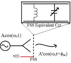
[image:2.595.356.493.199.319.2]In this paper, reconfigurable FSS are proposed as phase modulators for DAM. FSS have been previously proposed as amplitude modulators in [6]. Integrating varactor diodes within FSS allows their resonant frequencies to be altered by a bias
Fig. 1. Phase modulation with FSS
voltage [7]. This has been used previously to steer directional antenna beams [8] and to scramble GSM signals passing through a wall [9]. Using this technique, the transmitted phase of an antenna loaded with such FSS can produce a phase modulator suitable for use in Phase Shift Keying (PSK) communication systems. This concept will be analysed, and an FSS and antenna will be designed, simulated and characterised for QPSK modulation over a range of radiation angles.
II. DAMWITHFSS
Fig. 2. FSS unit cell design
III. FSS DESIGN
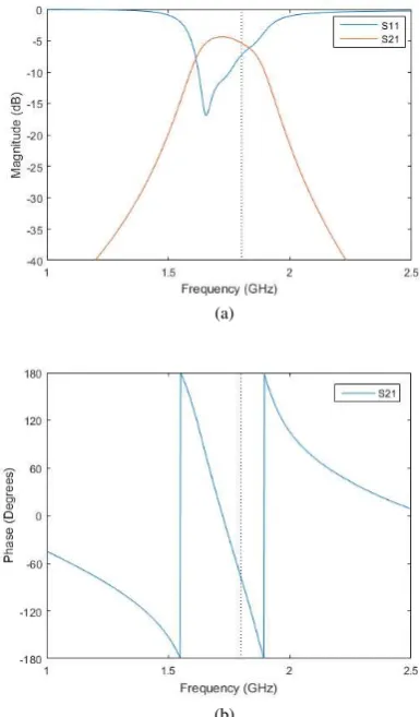
In order to obtain phase change for modulation in the trans-missive region of an FSS’s frequency response, a bandpass unit cell design is required. For this reason, and for their stability with angle of incidence, a square-loop design was chosen (Fig. 2). The dimensions were chosen to give operation at 1.8GHz, a typical wireless communication frequency. In order to provide 360◦ possible phase change for as little magnitude variation
as possible, three layers of the designed FSS were used, with each layer λ/4m from the next.
To assess its use as a phase modulator, the FSS design was simulated in CST Microwave Studio in free space, using Floquet boundaries to approximate an infinitely sized three-layer surface. PEC was used for the conducting surfaces on a 0.8mm FR4 substrate with a dielectric constant ofǫ= 4.3. The varactor diodes were modelled as lumped elements with the properties of SMV147 diodes, chosen for their low ca-pacitance and large tuning range, from 0.7pF to 7pF. They were simulated with a series resistance of 4.9Ωand a series inductance of 0.7nH. It is mostly the diode resistance, which is high for a variable capacitor, that accounts for the 5dB loss at maximum transmission shown in simulation (Fig. 3), and also increases the slope away of magnitude at the edges of the response. The design frequency of 1.8GHz is shown with a dotted line in both the magnitude and phase plots.
The simulation shows 360◦ of phase change is possible for
8dB difference between the least and most transmissive points with realistic components. This is large, but practical PSK transmitters do not need to achieve 360◦ of phase
change-for example, QPSK requires only 270◦phase change between
its furthest constellation points, which is achievable for 3.5dB variation according to simulation. Both the overall loss and the magnitude difference of constellation points could be reduced by using lower resistance variable capacitors and low loss substrates.
IV. RECONFIGURABLEANTENNADESIGN
Previous simulations assumed each layer of FSS was an infinitely sized sheet of repeating unit cells in free space. In
(a)
(b)
Fig. 3. Simulated s-parameters of infinite 3-layer FSS, (a) magnitude (b) phase
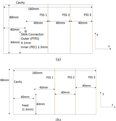
a practical free space system, a finite-sized FSS would suffer from edge effects, where signals diffract around each layer of the surface. To ensure that all the fields pass through a low form factor FSS, the FSS layers were placed in a conducting cavity. This also reduces the form factor of the system, as fewer unit cells of the FSS are required. It should be noted that putting the FSS in a cavity introduces a shift in resonant frequency of 350MHz compared with the free space case, which is accounted for by adjusting the diode capacitance. The use of a cavity lends itself to the idea of incorporating the FSS into a reconfigurable antenna.
[image:3.595.326.519.57.386.2](a)
[image:4.595.318.536.47.439.2](b)
Fig. 4. Reconfigurable antenna design, (a) bottom view, (b) side view
walls of the cavity.
The cavity itself was modelled as a set of zero thickness PEC plates in contact with the edges of the FSS, and the probe was a 40mm cylinder of 1.3mm thickness. It was surrounded at the base by a dielectric cylinder of 4.1mm thickness to recreate the geometry of an SMA input to the base of the probe. This probe was placed in the centre of the plate width, 40mm from the first FSS and 40mm from the back wall of the cavity. In order to connect the centre patches of the unit cells to a control signal, biasing lines are required on the FSS. To minimise their effect on the transmitted signal, they were designed and oriented such that the longest sections of track were orthogonal to the probe feeding the cavity. The lines were modelled as zero thickness PEC tracks with 1 mm width.
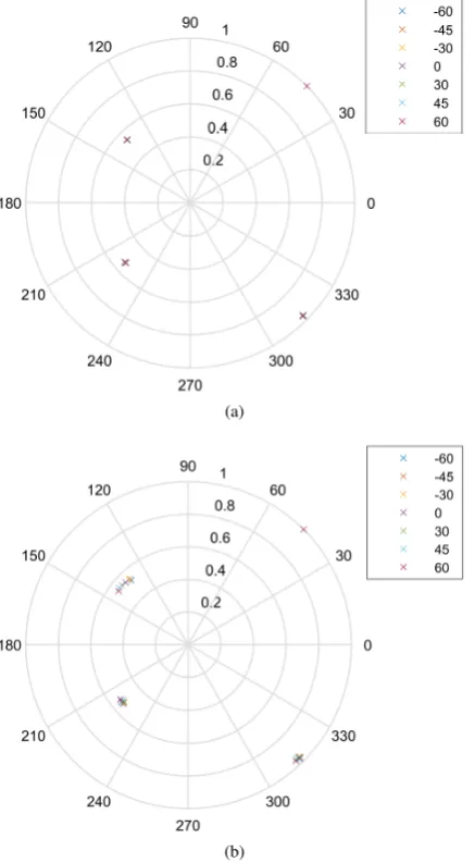
The farfield simulations of the reconfigurable antenna with incorporated FSS in Fig. 5 show the change of magnitude and phase with respect to capacitance normalised to the field simulated for the cavity with no FSS. This shows that the 270◦
of phase rotation required to produce a QPSK constellation can be achieved by this antenna design, where the chosen points are shown as dotted lines in Fig. 5. There is 5.3dB variation between the most transmissive and least transmissive points in this range. There is some loss in the centre of the pass region, and the minimum loss in the FSS is simulated at -5dB when the fully loaded reconfigurable antenna is compared with an empty cavity. This loss and the variation over the phase range can be reduced by using lower loss variable capacitors, as varactor diodes, and in particular SMV1247 diodes, have large series resistances, especially at high frequencies of operation. In order to examine the stability of the constellation pro-duced by the reconfigurable antenna modulator with angle to the antenna, the farfield phase and magnitude were simulated at various angles in azimuth and elevation an equivalent distance into the farfield. Fig. 6 shows the constellation points
0.9 1 1.1 1.2 1.3 1.4
Capacitance (pF) -20
-18 -16 -14 -12 -10 -8 -6 -4 -2 0
Normalised Farfield Magnitude (dB)
(a)
0.9 0.95 1 1.05 1.1 1.15 1.2 1.25 1.3 1.35 1.4
Capacitance (pF)
-150 -100 -50 0 50 100 150
Phase (Degrees)
(b)
Fig. 5. Simulated (a) magnitude, (b) phase of reconfigurable antenna with changing capacitance at boresight in the farfield, normalised to empty cavity simulation
as described previously in Fig. 5, with capacitances at 0.98, 1.08, 1.18 and 1.29pF producing the different phases. Each set is normalised so the constellation point at 1.08pF has magnitude 1 and phase π/4. With azimuth (Fig. 6a), the constellation varies very little over a 120◦beamwidth, with a
maximum phase variation of 1.05◦at the 1.29pF constellation
point. The magnitude variation within each constellation varies between 5.40dB at boresight and 5.48dB at 60◦ azimuth. It
should be noted that in the x-z plane, as defined by the coordinates in Fig. 5, the phase and magnitude variation is symmetrical around 0◦. This is not true, however, for variation
in elevation (y-z plane) (Fig. 6b), where slight differences between symmetrical angles occur. The phase variation is also more noticeable but still slight, with a maximum variation of 11.1◦, which here occurs at the 0.98pF constellation point.
[image:4.595.63.268.52.266.2](a)
[image:5.595.58.277.52.449.2](b)
Fig. 6. Constellation variation with angle, with each constellation normalised to maximum point at pi/4, (a) x-z plane, (b) y-z plane
it at 60◦ elevation. As such, the FSS modulator is stable with
angle within a 120◦ beamwidth, with maximum changes of
11.1◦ in phase and 0.15dB in magnitude of individual points
between different viewing positions.
V. CONCLUSION
A reconfigurable antenna incorporating FSS for PSK DAM systems has been designed, simulated and characterised. It shows 270◦ of phase rotation for QPSK can be achieved
with 3.5dB magnitude variation, with stability across a 90◦
beamwidth in both elevation and azimuth.
ACKNOWLEDGMENT
This work is funded by an Industrial CASE award from EPSRC with industrial partners NEC and BT.
REFERENCES
[1] A. Raghavan, N. Srirattana, and J. Laskar, Efficiency Enhancement of RF Power Amplifiers. Wiley-IEEE Press, 2008, pp. 173– 198. [Online]. Available: http://ieeexplore.ieee.org/xpl/articleDetails.jsp? arnumber=6130105
[2] A. Babakhani, D. B. Rutledge, and A. Hajimiri, “Transmitter architectures based on near-field direct antenna modulation,”Solid-State Circuits, IEEE Journal of, vol. 43, no. 12, pp. 2674–2692, 2008.
[3] P. Daehee, K. Minhoe, and C. Dong-Ho, “Novel single-RF MIMO system based on repetitive pulse width modulation,”Communications Letters, IEEE, vol. 20, no. 1, pp. 165–168, 2016.
[4] M. A. Sedaghat, V. I. Barousis, M. R. R, ller, and C. B. Papadias, “Load modulated arrays: a low-complexity antenna,” IEEE Communications Magazine, vol. 54, no. 3, pp. 46–52, 2016.
[5] M. Manteghi, “A wideband electrically small transient-state antenna,”
IEEE Transactions on Antennas and Propagation, vol. 64, no. 4, pp. 1201–1208, 2016.
[6] G. I. Kiani, T. S. Bird, and K. L. Ford, “60 GHz ASK modulator using switchable FSS,” in Antennas and Propagation Society International Symposium (APSURSI), 2010 IEEE, Conference Proceedings, pp. 1–4. [7] C. Mias, “Waveguide and free-space demonstration of tunable frequency
selective surface,”Electronics Letters, vol. 39, no. 11, pp. 850–852, 2003. [8] M. Sazegar, Y. Zheng, C. Kohler, H. Maune, M. Nikfalazar, J. R. Binder, and R. Jakoby, “Beam steering transmitarray using tunable frequency se-lective surface with integrated ferroelectric varactors,”IEEE Transactions on Antennas and Propagation, vol. 60, no. 12, pp. 5690–5699, 2012. [9] J. Roberts, K. L. Ford, and J. M. Rigelsford, “Secure electromagnetic