UNIVERSITI TEKNIKAL MALAYSIA MELAKA
BUS TRACKER BY USING GLOBAL POSITIONING SYSTEM
(GPS) AND GLOBAL SYSTEM MOBILE (GSM)
This report is submitted in accordance with the requirement of Universiti Teknikal Malaysia Melaka (UTeM) for the Bachelor Degree in Electronic Engineering
Technology (Telecommunication) with Honors.
by
ZUBAIR BIN ABDUL MALIK
B071110094
920111145379
FACULTY OF ENGINEERING TECHNOLOGY
UNIVERSITI TEKNIKAL MALAYSIA MELAKA
BORANG PENGESAHAN STATUS LAPORAN PROJEK SARJANA MUDA
TAJUK: Bus Tracker by using Global Positioning System (GPS) and Global System Mobile (GSM)
SESI PENGAJIAN: 2014/15 semester 1
Saya ZUBAIR BIN ABDUL MALIK
mengaku membenarkan Laporan PSM ini disimpan di Perpustakaan Universiti Teknikal Malaysia Melaka (UTeM) dengan syarat-syarat kegunaan seperti berikut:
1. Laporan PSM adalah hak milik Universiti Teknikal Malaysia Melaka dan penulis. 2. Perpustakaan Universiti Teknikal Malaysia Melaka dibenarkan membuat salinan untuk
tujuan pengajian sahaja dengan izin penulis.
3. Perpustakaan dibenarkan membuat salinan laporan PSM ini sebagai bahan pertukaran antara institusi pengajian tinggi.
4. **Sila tandakan ( )
SULIT
TERHAD
TIDAK TERHAD
(Mengandungi maklumat yang berdarjah keselamatan atau kepentingan Malaysia sebagaimana yang termaktub dalam AKTA RAHSIA RASMI 1972)
(Mengandungi maklumat TERHAD yang telah ditentukan oleh organisasi/badan di mana penyelidikan dijalankan)
Alamat Tetap:
Tarikh: ________________________
Disahkan oleh:
Cop Rasmi:
Tarikh: _______________________
i
DECLARATION
I hereby, declare that this thesis title “Bus Tracker by Using Global Positioning System (GPS) and Global System Mobile (GSM)” is the result of my own research
paper except as cited in the references.
Signature : ______________________
Name
: ZUBAIR BIN ABDUL MALIK
ii
APPROVAL
This report is submitted to the Faculty of Engineering Technology of UTeM as a partial fulfillment of the requirements for the degree of Bachelor of Engineering Technology (Telecomunication) with (Hons.). The member of the supervisory is as follow:
iii
ABSTRAK
iv
ABSTRACT
v
ACKNOWLEDGEMENT
Alhamdulillah, most grateful to Almighty ALLAH S.W.T. for blessing me with good health and providing ideas in completing this project successfully.
First of all, I would like to thank Encik Nurulhalim Bin Hassim as my supervisor during this Projek Sarjana Muda (PSM). He gave support and assistance to me, especially the exposure of the C language programming process. Without him, I was facing a lot of problem in completing this project.
I would also like to thank to my Universiti Teknikal Malaysia Melaka for providing this great opportunity and ample time for me to have my final year project completed within a year. Thanks for this precious time and helpful guidance. Honestly, it is the most valuable experience for me to explore and expose myself to the real engineering fields which demands for equal with knowledge and management skills.
Besides that, lots of love for my family especially my father Abdul Malik Bin Packir Mohammed for giving continuous supports throughout this four years. To my siblings who are always there by my side to encourage, advice and support during this entire project.
vi
TABLE OF CONTENTS
Title
Declaration
i
Approval
ii
Abstrak
iii
Abstract
iv
Acknowledgement
v
Table of Contents
vi
List of Tables
x
List of Figures
xi
List Abbreviations, Symbols and Nomenclatures
xiii
CHAPTER
1.
INTRODUCTION
1.1.
Project Background
1
1.2.
Problem Statement
2
1.3.
Objective
3
vii
2.
LITERATURE REVIEW
2.1.
Overview
5
2.2.
Background of Tracking Device
5
2.3.
Global Positioning System (GPS)
2.3.1.
GPS Background Information
6
2.3.2.
Longitude and Latitude Co-Ordinate
8
System
2.3.3.
GPS Signal Structure
10
2.3.4.
Three Segments of GPS
11
2.4.
Global System Mobile (GSM)
2.4.1.
GSM Background Information
13
2.4.2.
GSM Standard Operation
14
viii
3.
METHODOLOGY
3.1.
Overall Project Structure
17
3.2.
Expected Result
19
3.3.
Project Block Diagram
20
3.4.
SKM53 GPS Starter Kit
3.4.1. General Description
21
3.4.2. Mechanical Specification
23
3.5.
SKGPS-53 Module Starter Kit
3.5.1. General Description
24
3.5.2. Product Layout
25
3.6.
Flowchart Process
27
3.7.
GSM Modem
29
3.8.
MAX232
29
4.
RESULTS AND DISCUSSION
4.1.
Discussion
30
4.2.
Hardware
4.2.1. Circuit Design
31
ix
4.3.
Software
35
4.4.
Analysis
37
4.5.
Flowchart GSM Coding
40
5.
CONCLUSION AND FUTURE RECOMMENDATION
5.1.
Conclusion
43
5.2.
Future Recommendation
44
6.
REFERENCE
45
x
LIST OF TABLES
TABLE TITLE PAGE
2.1 GSM Bands information by country 14
3.1 Antenna specification in SKM53 module 19
3.2 SKM53 pin description 20
3.3 The description of component in SKGPS-53 24
4.1 Comparison between the actual result and the error result 35
xi
LIST OF FIGURES
Figure TITLE PAGE
1.1 The Statistic of Crime at the Bus Station by SPAD 4
2.1 The Earth Divided into Longitude and Latitude 7
2.2 Biphase Modulation of GPS signal 9
2.3 Three Segments of GPS 11
2.4 GSM World Coverage Map and GSM Country 13
3.1 The progressing from the beginning of the thesis 16
3.2 Process flow by using GPS system to detect the location 17
3.3 The block diagram for PIC 18F26K22 18
3.4 Actual view of SKM GPS starter kit 19
3.5 SKM53 pin package 20
3.6 Top View of SKM53 21
3.7 Vertical view of SKM53 21
3.8 Horizontal view of SKM53 21
xii
3.10 SKGPS-53 layout 23
3.11 The process flow of the Tracking Device to the user 25
3.12 GSM module 26
3.13 MAX232 26
4.1 Voltage regulator circuit 28
4.2 Buzzer, PIC 18F26K22 and Nokia 3310 LCD 28
4.3 Switch, SKGPS module, MAX232 and DB9 serial port 29
4.4 The layout of PCB by using Proteus 7 Professional software 30
4.5 After complete the etching process (upper view) 30
4.6 The negative design of the PCB by using Proteus 7 Professional 31 Software
4.7 After complete the etching process (lower view) 31
4.8 The combination coding into the microcontroller 32
4.9 Shown the command in float Array loop in 204 city 33
4.10 Location of latitude and longitude in cities library 34
4.11 The wrong/error result obtain (Sibu) 35
xiii
LIST OF ABBREVIATIONS
BPSK - Bi-Phase Shift Keying
CDMA - Code Division Multiple Access
CEPT - European Conference of Postal and Telecommunication Administrations
DOD - Department of Defense
EFR - Enhanced Full Rate
FOC - Full Operational Capability GPS - Global Positioning System
GSM - Global System Mobile
IOC - Initial Operational Capability LPC - Linear Predictive Coding
ME - Mobile Equipment
PCB - Printed Circuit Board
SPAD - Suruhanjaya Pengangkutan Awan Darat SIM - Subscriber Identity Module
SMS - Short Message Service
UMTS - Universal Mobile Telecommunication System USB - Universal Serial Bus
1
CHAPTER 1
INTRODUCTION
1.1 Project Background
A vehicle tracking system consists of an electronic device installed on a vehicle so that it can be tracked by its owner or a third-party for its position. Most of the vehicle tracking system uses Global Positioning System (GPS) to get an accurate reading of the vehicle position. Communication components such as cellular Global System Mobile (GSM) and satellite transmitter will be combined to transmit the vehicle’s position to remote user. Vehicle’s information can be viewed by using a software on a computer.
Vehicle tracking systems are commonly used by fleet operators for fleet management functions such as routing, dispatching, on-board information display and security. Other applications include monitoring driving behavior, such as an employer monitoring an employee, or a parent monitoring a teenaged driver. Vehicle tracking systems are also popular in consumer vehicles as a theft prevention and retrieval device. The police can simply follow the signal emitted by the tracking system and locate the stolen vehicle. When used as a security system, a Vehicle Tracking System may serve as either an addition to or replacement for a traditional Car alarm. The existence of vehicle tracking device then can be used to reduce the insurance cost, because the loss-risk of the vehicle installed with this system drops significantly.
2 professionals can easily access their real-time locations. For example, in unfamiliar areas they can locate themselves as well as their customers and prospects. They could also get driving directions and add nearby last-minute appointments. Benefits from this system include increased productivity, reduced driving time and increased time spent with customers and prospects.
It is has been reported that, with similar system the users has been able to get many benefits by auditing employee hours to insure better utilization of vehicles. This system has also proven its ability to reduce mileage hence, reducing the fuel costs through monitoring unauthorized private use of company vehicles (Sabudin, 2010). Productivity will also be increased through better budgeting of time and resources.
1.2 Problem Statement
Proposed design for this project is mainly to find cost-effective, reliable and accurate vehicle tracking device. When vehicles were spread out all over, the user often found it difficult to keep track of what was happening. They require some type of system to determine where each vehicle was at any given time and for how long it has travelled. There is also the need for tracking when an owner is trying to locate a lost vehicle.
GSM and GPS based tracking system will provide effective, real time vehicle location reporting. A GPS- GSM based tracking system will inform where the vehicle is and where it has been, and how long it has been at that location. The system uses geographic position and time information from the Global Positioning Satellites. The On-Board module consists of GPS receiver and a GSM modem.
3 transportation management. The use of GSM and GPS technologies allows the system to track vehicle and to provide the most up-to-date information about ongoing trips.
We can also use it for application that require real time control. As an example this system also can be used for time traffic surveillance. It could be also used as a valuable tool for tourist.
1.3 Objective
The objective of this project is to design and develop a Vehicle Tracking System using GPS and GSM Technologies. In order to fully understand both GPS and GSM technology, the research will study on how both technology works. The objective of this project are:
I. To study and investigate the basic operation of the GPS module and GSM module. II. To design and develop a tracking system.
4
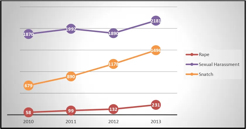
1.4 Project Significance
This study was chosen because of the concerns over safety of public transport users especially women. For example, majority of women using the public transport at night are usually without any company. The statistic of rape and rob cases at the bus stop are increasing every year (Jusoh, 2010). Jusoh, M. T. B., 2010. Statistik ragut 2010, (SPAD). Thus, the main objective is to ensure safety of women passenger so that they can manage their travelling time with flexibility.
[image:20.612.95.519.368.589.2]The passenger can manage their time better if there are able to determine the current location of the bus, without having to wait long hours at the bus stop. This can reduce the crime cases in Malaysia and at the same time the user can optimize their time better.
Figure 1.1: The Statistic of Crime at the Bus Station by SPAD.
58 99 132
231
1870 1992 1890
2181
679
890
1178
1496
2010 2011 2012 2013
Rape
Sexual Harassment
5
CHAPTER 2
LITERATURE REVIEW
2.1 Overview
This thesis relies heavily on the use of both GPS and GSM. This chapter will begin with an overview of the Global Positioning System explaining about the structure of GPS and the characteristics of GPS. Furthermore, details about the longitude and latitude and how to understand about the location tracking device will be explored.
2.2 Background of Tracking Device
6
2.3 Global Positioning System (GPS)
2.3.1 GPS Background Information
The GPS System was created and realized by the American Department of Defense (DOD) and was originally based on and run with 24 satellites (21 satellites being required and 3 satellites as replacement). Nowadays, about 30 active satellites orbit the earth at a distance of 20200 km (Hoffman-Wellenhof, B, H. Lichtenegger and J. Collins 2001, p. 382).
GPS satellites transmit signals which enables a GPS receiver to extract its location, if it is positioned on the surface of the earth, in the earth atmosphere or in a low orbit. GPS is being used in aviation, nautical navigation and for the orientation of shore. The GPS signal can be used without a fee by any person in possession of a GPS receiver. Furthermore, it is used in land surveying and other applications where the determination of the exact position is required. At first only 18 satellites were be operated. In 1988 the number of satellites is raised to 24, as the functionality is not satisfactory with only 18 satellites (Thuong Le-Tien, Vietnam in 2010).
7 In 1989, the first Block II satellite was installed and activated. Temporal deactivation of the selective availability (SA) was done during the Gulf war. In this period civilian receivers were used as not enough military receivers were available. On July 01, 1991 SA is activated again. The Initial Operational Capability (IOC) was announced in 1993 (Thor Hogan, Vic Villhard 2004, p. 12). In the same year it was decided to authorize the world wide civilian use free of charge.
8
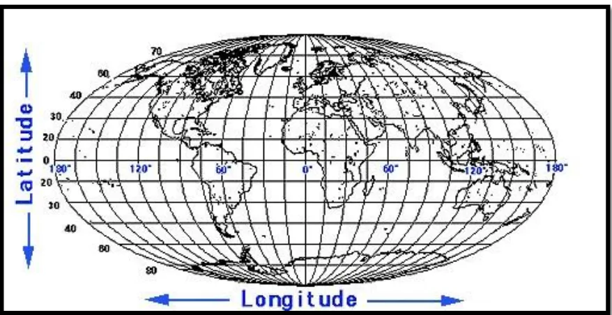
2.3.2 Longitude and Latitude Co-Ordinate System
[image:24.612.95.534.319.545.2]The location of any point on a planar surface can be fully described by both a horizontal and a vertical co-ordinate. Had the earth been truly flat and rectangular as it had been perceived in the past, a simple equally spaced grid system could be used to describe any location on earth. However, the earth is neither flat nor rectangular. It is not even a perfect sphere. The fact of the matter is the earth is an oblate ellipsoid, a slightly egg shaped sphere. A grid-like system of latitudes and longitudes was devised to describe precise locations on earth. Both latitude and longitude are measured in terms of degrees, (°). Figure 2.1 shows a map of the earth including basic longitude and latitude information.