This is a repository copy of
Mobile optical wireless system using fast beam Angle, delay
and power adaptation with angle diversity receivers
.
White Rose Research Online URL for this paper:
http://eprints.whiterose.ac.uk/96367/
Version: Accepted Version
Proceedings Paper:
Alhartomi, MA, Alsaadi, FE and Elmirghani, JMH (2012) Mobile optical wireless system
using fast beam Angle, delay and power adaptation with angle diversity receivers. In:
International Conference on Transparent Optical Networks. 14th International Conference
on Transparent Optical Networks (ICTON), 02-05 Jul 2012, Coventry, UK. IEEE . ISBN
978-1-4673-2228-7
https://doi.org/10.1109/ICTON.2012.6253885
© 2012 IEEE. Personal use of this material is permitted. Permission from IEEE must be
obtained for all other uses, in any current or future media, including reprinting/republishing
this material for advertising or promotional purposes, creating new collective works, for
resale or redistribution to servers or lists, or reuse of any copyrighted component of this
work in other works.
[email protected] https://eprints.whiterose.ac.uk/
Reuse
Unless indicated otherwise, fulltext items are protected by copyright with all rights reserved. The copyright exception in section 29 of the Copyright, Designs and Patents Act 1988 allows the making of a single copy solely for the purpose of non-commercial research or private study within the limits of fair dealing. The publisher or other rights-holder may allow further reproduction and re-use of this version - refer to the White Rose Research Online record for this item. Where records identify the publisher as the copyright holder, users can verify any specific terms of use on the publisher’s website.
Takedown
If you consider content in White Rose Research Online to be in breach of UK law, please notify us by
Mobile Optical Wireless System using Fast Beam Angle, Delay and
Power Adaptation with Angle Diversity Receivers
Mohammed A. Alhartomi1, *, Fuad E. Alsaadi2, #, Jaafar M.H. Elmirghani3, *, Senior Member IEEE
* School of Electronic and Electrical Engineering, University of Leeds, Leeds, LS2 9JT, UK
# Faculity of Engineering King Abdulaziz University, Jeddah, Saudi Arabia
1[email protected], 2[email protected], 3[email protected]
ABSTRACT
In this paper, we introduce a novel fast angle and power adaptation method in optical wireless (OW) systems. The fast angle and power adaptive line strip multibeam system (FAPA-LSMS) can identify the optimum spots distribution based on a divide and conquer (D&C) algorithm and can achieve a signal-to-noise ratio (SNR) performance comparable to that obtained using the normal APA-LSMS. This results in a significant reduction in the system adaptation time by a factor of 20. The proposed FAPA system makes use of delay adaptation to minimize the delay spread at the receiver. A significant reduction in the delay spread by a factor of 50 can be achieved compared to the non adaptive LSMS. The proposed system improves the SNR by 50 dB over a conventional diffuse system.
Keywords: Optical wireless, signal-to-noise ratio (SNR), fast beam angle adaptation, beam delay and power
adaptation.
1. INTRODUCTION
The growing demand in high data rate transmission has encouraged the investigation of optical wireless (OW) systems as information carriers in the indoor environment. This encouragement is due to their potential high-speed transmission, immunity to electromagnetic interference and inexpensive sub-systems components such as light emitting diodes (LED) and silicon detectors [1]. OW systems offer a number of potential advantages over their radio frequency counterparts. These include unregulated large bandwidth, the possibility of frequency reuse since the optical signals do not penetrate walls or opaque objects, security and freedom from spectrum regulation and licensing [1]-[2]. However, the design challenges of OW systems lie in two major impairments when employing intensity modulation with direct detection (IM/DD). These impairments include additive noise due to sunlight and artificial light and multipath dispersion. The former degrades the signal to noise ratio (SNR) while the latter limits the link capacity.
Indoor OW systems are classified into two main configurations: direct line-of-sight (LOS) and diffuse systems. Direct LOS links improve power efficiency and minimize multipath dispersion, but inherently require transmitter-receiver alignment and can suffer from shadowing. Diffuse systems offer robust links and reduce the effect of shadowing, but suffer multipath dispersion in addition to higher path losses compared to direct LOS links. Transmitter beam diversity has been shown to be an attractive technique that combines the advantages of both direct LOS and pure diffuse links leading to reduced multipath dispersion and shadowing mitigation [3]-[5]. Static multibeam intensities can be practically produced by using computer generated holograms (CGHs). Furthermore, diversity reception has been introduced as an effective scheme that helps combat the destructive effects of multipath dispersion and ambient light interference. The combination of spot-diffusing technique such as a line strip multibeam system (LSMS) and diversity receivers can offer an improvement in link performance compared to conventional diffuse system (CDS) [6]. However, mobility and shadowing can significantly degrade the SNR of spot-diffusing optical wireless systems [8].
Previous work has shown that employing power adaptation with spot-diffusing systems can significantly enhance the link performance [9]-[10]. This approach can adaptively distribute the power among unobstructed beams providing a degree of robustness against shadowing and beam blockage. Further improvement can be achieved by adapting the beam angle to allow clustering the diffusing spots at positions near the receiver regardless of the transmitter position [11]-[12]. The combination of these two methods (beam angle adaptation and transmit power adaptation) can effectively reduce the effect of mobility and shadowing as well as improve the SNR at the expense of complexity. Another approach that has been introduced to mitigate multipath dispersion and ISI is beam delay adaptation as in [13].
In this paper, we propose a novel method (fast beam angle, delay and power adaptation) coupled with an angle diversity receiver to adequately reduce the effect of mobility and shadowing and the associated impacts in terms of weak received optical power and reduction in bandwidth. The rest of the paper is organized as follows: Section 2 gives a description of the simulation environment. The transmitter configurations including the new adaptive method are given in Section 3. Section 4 outlines the results and conclusions are drawn in Section 5.
2. PROPAGATION ENVIRONMENT
The optical transmitter and receiver were always placed on the communication floor (CF), above the ground level. The multibeam transmitter is assumed to produce a total optical power of equally distributed among the spots (80 diffusing spots are considered in our case and each spot is assigned ). Beam powers and angles can be adapted by using a liquid crystal device which has to response times [14].
Intensity modulation with direct detection (IM/DD) is the preferred method for OW communication links due to its simplicity [2]. An indoor OW channel can be fully characterized by its impulse response as [7]:
(1)
where is the received instantaneous current at the output of the photodetector at a certain position, is the absolute time, is the transmitted instantaneous optical power, denotes convolution and is the photodetector responsivity. The ambient background noise (BN) is denoted by which is independent of the received signal and is modelled as white and Gaussian. The room illumination is assumed to be provided by eight halogen spotlights ('Philips PAR 38 Economic' (PAR38)). The eight spot lights were placed on the ceiling at coordinates of
( ), ( ), ( ), ( ), ( ), ( ), ( )
and ( ). Each spotlight emits and was modelled as a Lambertian radiant intensity with order , which corresponds to a semi angle of .
In order to quantify the proposed system’s performance under mobility, the multibeam transmitter was placed at two
different locations on the CF: ( ) and ( ), in an upright position and emitted total optical power with an ideal Lambertian radiation pattern. Five multibeam transmitter configurations: CDS, LSMS, beam power adaptive LSMS (PA-LSMS), beam angle and power adaptive (APA-LSMS) and FADPA-LSMS were considered.
3. TRANSMITTER CONFIGURATIONS
In this section, a fast beam delay, power and angle adaptation (FADPA) multibeam transmitter configuration is illustrated, analyzed and compared with CDS, LSMS, PA-LSMS and APA-LSMS configurations in order to identify the best OW system among those considered.
3.1 CDS, LSMS and PA-LSMS
CDS is the basic OW system configuration and has been widely investigated [1]-[2]. It is simulated with a wide FOV receiver. The OW system performance has been enhanced by adopting multibeam configurations such as LSMS or beam clustering method (BCM) [7]. LSMS uses a diffusing spot distribution pattern where a line of spots with equal intensities (in our case 80 spots) is formed in the middle of the ceiling, i.e. at x = 2 m and along the y-axis when the transmitter is placed at the centre of the room. The structure in the PA-LSMS is similar to that in LSMS, but the power is adaptively distributed among the spots in PA-LSMS with the aim of maximizing the receiver SNR.
3.2 APA-LSMS and FADPA
The distance between the diffusing spots and the receiver is a key factor in mobile indoor multibeam OW systems. In order to identify the optimum spots distribution an efficient method that involves beam angle adaptation was introduced [11]-[12]. This technique coupled with power adaptation can considerably achieve higher SNR levels at the expense of complexity associated with the computation time required to identify the optimum locations of the diffusing spots. Therefore, a new fast beam angle and power adaptation (FAPA) algorithm is introduced here to effectively reduce the system adaptation time. Our proposed FAPA system makes use of delay adaptation to further minimise the delay spread at the receiver. An APA-LSMS configuration is modelled following the procedure given in [12] and is used for comparison purposes in order to evaluate the improvements offered through our proposed novel configuration (FADPA).
The fast beam angle, delay and power adaptation can be implemented in optical transmitters with an adaptive hologram using a liquid crystal device. The adaptive hologram (through the liquid crystal device) can produce spots whose locations and intensities can be adapted by altering the transmission angles ( , ) within boundary angles ( ) and ( ). The boundary angles can take values equal to or within to with respect to the
transmitter’s normal in both and directions. The fast algorithm can determine the optimum location that yields the best receiver SNR based on a divide and conquer (D&C) algorithm. It arbitrarily divides the entire room (including the ceiling and walls) into four quadrants with boundary angles of ( to ) and ( to ) in both axes. It produces a single spot and scans this spot with a step angle along a number of possible locations in the entire room to identify the spot location that results in the best receiver SNR. The angle step is chosen large in the first iteration (in our case the fast algorithm starts with of 17.7o which allows the spot to move 64 cm) to reduce the number of
locations that have to be scanned. The angle is then reduced by factor of two in each following iteration. The position that results in the best receiver SNR is identified as a optimum location, and the quadrant that includes this sub-optimum location is selected as a new scanning area for the next iteration. A number of iterations is carried out until the final optimum location is identified. The results show that scanning 640 possible locations with our fast “Divide and Conquer” algorithm produces SNR performance comparable to the case when the classical APS-LSMS scans 12500 locations. This translates to a reduction in the computation time by a factor of 20 approximately. The FADPA algorithm can be described as follows:
( ). In the first iteration, these angles are defined from ( to ) and ( to ) in -axis and -axis, respectively (i.e., the boundary angles associated with the first quadrant are to in the -axis and - to in the -axis.).
2. Generate a single spot and move it by changing the beam angles within ( ) and ( ) in steps of ( starts with in the first iteration in order to reduce the number of locations to be scanned) in order to determine the sub-optimum location.
3. Compute the receiver SNR at each step and send a control feedback signal at low rate to inform the transmitter of the SNR associated with the step.
4. Record the transmission angles and where the receiver SNR is sub-optimal.
5. Determine the position coordinates ( , , ) of the spot that produces the sub-optimum SNR based on its transmission angles and .
6. From and , the transmitter identifies the quadrant that includes the sub-optimum location and assigns its associated boundary angles as the boundary angles of the new scanning area ( & ) to configure the adaptive hologram for the next iteration.
7. Divide the new scanning area into four quadrants and reduce the by factor of two.
8. Repeat steps 1-4 to identify the optimum location. Note that iterations stop when in which case all the spots just touch each other in the line strip where each spot has a diameter of 1 cm.
9. Assign the sub-optimum location ( , , ) as an optimum location with coordinates of ( , , ). 10.Generate a line strip of spots (80 spots in our case) whose centre is this coordinate, i.e ( , , ).
The MAC protocol should include a repetitive training period that allows steps 1-4 to be performed. Training should be carried out at the rate at which the environment changes. This is usually a slow rate commensurate with human motion. The previous steps show the fast algorithm used to adapt the beam angles which leads to a significant reduction in the computation time required to identify the optimum spots distribution. The next step is to adapt the beam power and delay which can be performed as follows
1. Turn on each spot individually, compute the power received at the receiver and calculate the SNR and mean delay ( ).
2. Send a feedback signal at low rate to inform the transmitter of the and SNR associated with each spot. 3. Repeat step 1 and 2 for all the spots.
4. Introduce a differential delay as max to all the spots.
5. Redistribute the power among the spots in proportional to their SNR.
4. RESULTS
In this section, a new fast beam angle, delay and power adaptive (FADPA) multibeam transmitter configuration coupled with an angle diversity receiver is analyzed and compared with beam delay and power adaptive LSMS (DPA-LSMS), PA-LSMS, LSMS, and CDS. Our proposed systems are evaluated when the multibeam transmitter is placed on the communication floor (CF) at ( ) and ( ).
4.1 Impulse Response and Delay Spread Evaluation
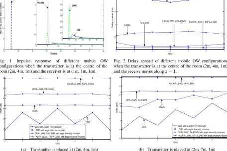
The channel impulse response specifies the received optical power that results from multipath propagation. In order to characterize such channel behaviour, we adopt the channel impulse response model based on spot-diffusing geometry coupled with diversity reception. Fig. 1(a) shows the impulse response of different mobile OW configurations when the transmitter is stationary at the room centre (2m, 4m, 1m) and the receiver is at the room corner (1m, 1m, 1m). The results show an increase in the received power level by factor of 10 when a diversity spot-diffusing system replaces the conventional diffuse system (CDS). The received power can be significantly enhanced when beam angle, delay and power adaptation is employed. This comes with a significant reduction in the signal spread.
In the presence of transmitter and receiver mobility, delay Spread in an important criterion.
A
comparison of the delay spread of different mobile OW configurations is depicted in Fig. 1(b) when the transmitter is stationary at the room centre and the receiver moves along the x=1 line. The results show that the proposed system (FAPA-LSMS) making the use of delay adaptation can reduce the delay spread from 0.54 ns to 0.01 ns compared to the non adaptive spot diffusing system.4.2 SNR Performance Analysis
Indoor mobile OW communication systems are strongly impaired by the shot noise induced by ambient light. Considering the impact of pulse spread caused by ISI where Ps1 - Ps0 accounts for the eye opening at the sampling
instant, the SNR is given by:
, (1)
multibeam system combined with an angle diversity receiver is assessed under the impairments of very directive shot noise, multipath propagation and mobility. Regardless of the transmitter position, beam angle adaptation can target the spots at the optimum location that yields the best SNR at the receiver. Our proposed system offers 16 dB SNR gain compared to the PA-LSMS.
Fig. 1 Impulse response of different mobile OW configurations when the transmitter is at the centre of the room (2m, 4m, 1m) and the receiver is at (1m, 1m, 1m).
Fig. 2 Delay spread of different mobile OW configurations when the transmitter is at the centre of the room (2m, 4m, 1m) and the receive moves along .
(a) Transmitter is placed at (2m, 4m, 1m) (b) Transmitter is placed at (2m, 7m, 1m)
Fig.3 SNR performance of different mobile OW configurations when the receiver moves along .
5. CONCLUSIONS
In this paper, a novel fast angle and power adaptation method was introduced to the design of OW systems. The
system’s performance was evaluated in the presence of multipath dispersion, background noise and mobility. The aim
of the study is to mitigate the limitations of non LOS OW system. The beam angle adaptation can help the multibeam transmitter to automatically cluster its diffusing spots at the optimum position (on the ceiling and/or walls) that maximizes the receiver SNR. Our proposed FAPA system makes use of delay adaptation to minimize the delay spread at the receiver. The introduction of beam angle, delay and power adaptation can help reduce the delay spread by a factor of 50 compared to the spot-diffusing systems. An SNR improvement of 50 dB can also be achieved over the CDS.
REFERENCES
[1] F.R. Gfeller, U. Bapst, “Wireless in-house data communication via diffuse infrared radiation,” Proceedings of the IEEE, vol. 67, No.11, pp. 1474- 1486, Nov. 1979.
[2] J. M. Kahn and J. R. Barry, “Wireless infrared communications,” Proc. IEEE, vol. 85, No. 2, pp. 265–298, Feb. 1997. [3] S. Jovkova and M. Kavehard, “Multispot diffusing configuration for wireless infrared access,” Communications, IEEE
Transactions on, vol. 48, No. 6, pp. 970 –978, June 2000.
[4] Yun and M. Kavehrad, “Spot diffusing and fly-eye receivers for indoor infrared wireless communications,” in Proc. 1992 IEEE Conf. Selected Topics in Wireless Communications, Vancouver, BC, Canada, June 1992, pp. 286–292.
[5] S. Jivkova and M. Kavehard, “Multispot diffusing configuration for wireless infrared access,” IEEE Trans. Commun., vol. 48, No. 6, pp. 970–978, June 2000.
[6] J. Carruther and J. Kahn, “Angle diversity for nondirected wireless infrared communication,” Communications, IEEE Transactions on, vol. 48, No. 6, pp. 960 –969, June 2000.
[7] A. Al-Ghamdi and J. Elmirghani, “Spot diffusing technique and angle diversity performance for high speed indoor diffuse infra-red wireless transmission,” Optoelectronics, IEE Proceedings, vol. 151, No. 1, pp. 46 – 52, Feb. 2004.
[8] A. G. Al-Ghamdi and J. M. H. Elmirghani, “Performance comparison of LSMS and conventional diffuse and hybrid wireless
techniques in a real indoor environment,” IEE Proc. Optelectron., vol. 152, No. 4, pp. 199-204, August 2005.
[9] F. E. Alsaadi and J. M. H. Elmirghani, “Performance evaluation of 2.5 and 5 Gbit/s optical wireless systems employing a two
dimensional adaptive beam clustering method and imaging diversity detection,” IEEE J. Select. Areas Commun., vol. 27, No. 8, pp. 1507–1519, Oct. 2009.
[10] F. E. Alsaadi and J. M. H. Elmirghani, “Adaptive mobile line strip multibeam MC-CDMA optical wireless system employing
imaging detection in a real indoor environment,” IEEE J. Sel. Areas Commun., vol. 27, No. 9, pp. 1663–1675, Dec. 2009.
1 2 3 4 5 6 7
0 0.5 1 1.5 2 2.5 Y(m) D e la y s p re a d ( n s ) CDS LSMS PA-LSMS
FAPA-LSMS, APA-LSMS FADPA-LSMS, FADPA-LSMS
1 2 3 4 5 6 7
-10 0 10 20 30 40 50 Y(m) S N R ( d B )
CDS with a wide FOV receiver LSMS with angle diversity receiver DPA-LSMS, PA-LSMS with angle diversity receiver FADPA-LSMS, FAPA-LSMS with angle diversity receiver
CDS LSMS
(DPA-LSMS, PA-LSMS)
(FADPA-LSMS, FAPA-LSMS)
1 2 3 4 5 6 7
-20 -10 0 10 20 30 40 50 Y(m) S N R ( d B )
CDS with a wide FOV receiver LSMS with angle diversity receiver DPA-LSMS, PA-LSMS with angle diversity receiver FADPA-LSMS, APA-LSMS with angle diversity receiver CDS
LSMS DPA-LSMS, PA-LSMS
[image:5.595.80.533.104.244.2] [image:5.595.80.537.133.438.2][11] Alsaadi, F.E.; Elmirghani, J.M.H., “High-Speed Spot Diffusing Mobile Optical Wireless System Employing Beam Angle and Power Adaptation and Imaging Receivers,” Lightwave Technology, Journal of, vol.28, No.16, pp.2191-2206, Aug., 2010. [12] F.E. Alsaadi, J.M.H. Elmirghani, “Beam power and angle adaptation in multibeam 2.5 Gbit/s spot diffusing mobile optical
wireless system,” Selected Areas in Communications, IEEE Journal on, vol. 28, No.6, pp. 913-927, Aug. 2010.
[13] M.T. Alresheedi, J.M.H. Elmirghani, “Line strip multibeam spot diffusing optical wireless system employing beam delay and power adaptation with angle diversity detection,” Wireless Communications and Mobile Computing Conference (IWCMC), 2011 7th International , pp. 924-929, 4-8 July 2011.