Multi-Functional Antenna Array Assisted MC DS-CDMA
Using Downlink Preprocessing Based on Singular Value
Decomposition
Chong Xu, Bin Hu, Lie-Liang Yang and Lajos Hanzo
School of ECS., Univ. of Southampton, SO17 1BJ, UK.
Tel: +44-23-80-593 125, Fax: +44-23-80-593 045
Email:
{
cx05r, lly, lh
}
@ecs.soton.ac.uk, http://www-mobile.ecs.soton.ac.uk
Abstract— In this contribution we propose and investigate a transmitter preprocessing scheme designed for downlink transmission in multicarrier direct-sequence code-division multiple-access (MC DS-CDMA) systems using multiple base-station antenna arrays, where each antenna ar-ray employs multiple arar-ray elements. The transmitter preprocessing scheme is derived based on the singular value decomposition (SVD). Our transmitter preprocessing design is capable of supporting a high number of MC DS-CDMA users, while maintaining a high diversity gain at a low detection complexity at the remote mobile stations (MSs). The characteristics of MC DS-CDMA using the proposed transmitter preprocessing scheme are discussed and the achievable bit-error-rate (BER) performance is investigated, when assuming that each subcarrier experiencesflat Rayleigh fading. Our simulation results demonstrate that for a SVD-assisted MC DS-CDMA system usingM distinct transmit antenna arrays and time (T)-domain spreading sequences of lengthNe chips, the number of users supported can be as high asM Ne, since
NeandMnumber of users may be distinguished in the T-domain and spatial-or S-domain, respectively. Furthermore, the SVD-assisted MC DS-CDMA system is capable of supportingMN˙enumber of users at a near single-user BER performance.
I. INTRODUCTION
Multi-Carrier Direct Sequence Code Division Multiple Ac-cess (MC DS-CDMA) constitutes a high-flexibility multiple-access scheme, which is capable of providing a degree of freedom for system designers in comparison to both single-carrier DS-CDMA and frequency (F)-domain spread multicarrier CDMA (MC-CDMA) dis-pensing with T-domain spreading [1]–[3]. In [4], [5] the authors have proposed and investigated a MC DS-CDMA system, which employs multiple distinctλ/2-spaced base-station (BS) antenna arrays in order to achieve a high receive diversity [4] for the uplink (UL) or transmit diversity [5] for the downlink (DL) in the spatial or S-domain. Furthermore, as shown in [4], [5], when receiver or transmitter beamforming is employed, the proposed MC DS-CDMA system is capable of suppressing the interfering signals having direction-of-arrivals (DoAs) that are sufficiently different from that of the desired signal. To be more specific, in [5] the performance of multi-functional antenna array assisted MC DS-CDMA has been investigated, where the BS transmitter preprocessed the transmitted signals using steered space-time spreading (SSTS), which makes use of the knowledge of all the downlink users’ DOAs, but does not exploit the knowledge of the channel impulse responses (CIRs) of the DL channels. In this case the DL users experience severe multiuser interference (MUI), which may only be mitigated at the remote MSs with the aid of advanced multiuser detection (MUD) or interference cancellation schemes [6]. Recently, transmitter preprocessing techniques have received wide attention [7]–[12]. It has been shown that DL transmit diversity may
Acknowledgements: The financial support of the EPSRC, UK and that of the EU under the auspicies of the Phoneix and NEWCOM projects is gratefully acknowledged.
be readily achieved with the aid of transmitter preprocessing applied in the context of time-division duplexing (TDD), while the DL MUI may be mitigated by carrying out the required signal processing at the BS. Consequently, power-efficient MSs may be designed, which employ low-complexity algorithms. Therefore in this contribution we investigate the performance of the MC DS-CDMA system considered in [4], [5], when assuming TDD-based cellular communications and that the BS transmitter is capable of exploiting the knowledge of both the DoAs and the CIRs in the context of all the DL users. Specifically, we assume that the BS transmitter preprocesses the transmitted DL signals using SVD principles. The transmitter preprocessing scheme was designed for ensuring that the MC DS-CDMA becomes capable of simultaneously supporting a high number of users and of achieving the highest attainable diversity gain with the aid of low-complexity MS detectors. We will demonstrate that the attainable performance of MC DS-CDMA can be significantly enhanced, when our SVD-assisted transmitter preprocessing schemes is employed. Specifically, when usingM distinct transmit antenna arrays and T-domain spreading sequences of length Ne, the system becomes capable of supporting uptoM Neusers, while achieving a near-single-user BER performance. This is possible, sinceNe users may be uniquely identified in the T-domain, whileM users in the
S-domain. Furthermore, an attractive performance trade-off can be found between the number of users supported and the achievable diversity gain, as detailed in our forthcoming discourse.
II. SYSTEMDESCRIPTION
In this section we consider the transmitter and receiver models of our MC DS-CDMA system using multi-functional antenna arrays at the BS, which employs DL transmitter preprocessing based on the principles of SVD.
A. Transmitter Model
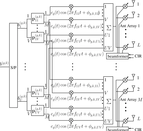
Fig. 1 shows the transmitter schematic of the DL MC DS-CDMA system, where the BS employsM transmit antenna arrays, each of which consists ofLarray elements. We assume that theMantenna arrays are set sufficiently far apart from each other, in order that their CIRs become independent. By contrast, the spacing of the L
Ant Array Ant Array 1
beamformer beamformer
CIR CIR
S/P
)
2 2
1 1
1
1 1 1
1 1
1
1 b(Ug,k) b(g,k)
1
b(g,k)
cg(t) cos (2πf11t+φg,k,11)
cg(t) cos (2πfU1t+φg,k,U1)
cg(t) cos (2πfUVt+φg,k,UV)
cg(t) cos (2πfUVt+φg,k,UV) cg(t) cos (2πf11t+φg,k,11)
cg(t) cos (2πfU1t+φg,k,U1) cg(t) cos (2πf1Vt+φg,k,1V) cg(t) cos (2πf1Vt+φg,k,1V)
V
UV U1
UV U1
V M
V
V
L M L M
M
M
p(UVg,k)
p(Ug,k1) p(g,k) 1V
p(g,k) 11
[image:2.612.64.293.61.272.2]
Fig. 1: Downlink transmitter schematic of MC DS-CDMA employing
Mtransmit antenna arrays, each of which hasLarray elements, when
BS transmitter preprocessing is employed.
We assume that the MC DS-CDMA system supportsK=KGDL
users, which are divided intoGuser-groups and each group contains Kusers. TheKusers in a given group, say groupg, share a common T-domain spreading sequence cg = [cg[0],· · ·, cg[Ne−1]]T of lengthNechips. Furthermore, it is assumed thatcgis orthogonal to cq. Following the serial-to-parallel (S/P) conversion stage of Fig. 1, the data bits to be transmitted to thekth downlink user in thegth
group can be expressed as
b(g,k)= b(1g,k), b (g,k) 2 , . . . , b
(g,k) U
T
, (1)
where a single bit is mapped toV subcarriers. Therefore, the total number of subcarriers in the MC DS-CDMA system considered is U V. Specifically, the subcarriers invoked for transmitting the uth, u = 1, . . . , U, bit of the kth user in the gth group are {fu1, fu2, . . . , fuV}.
As shown in Fig. 1, in the context of theuvth subcarrier, the data bitb(ug,k)isfirst preprocessed by anM-length vectorp(uvg,k), yielding M outputs corresponding to the M number ofL-element transmit
antenna arrays. Following preprocessing, the signals are spread using the T-domain spreading codecg(t) = Nn=0e−1cg[n]PTc(t−nTc),
where PTc(t) represents the typical rectangular chip waveform of
width Tc, while Tc represents the chip-duration, Ne = Ts/Tc denotes the spreading factor, Ts = U Tb is the symbol-duration, whileTbis the bit-duration. As shown in Fig. 1, following T-domain spreading, the resultant signals modulate the carrier and,finally, they are transmitted by theM antenna arrays, where the array elements’ signals may be weighted based on certain optimization criteria with the aid of our knowledge concerning the CIRs of the DL channels.
Based on the above discussions, it can be shown that the baseband equivalent signals transmitted to theKusers in thegth group can be
expressed as
s(g)(t) = 2P V L
K
k=1 U
u=1 V
v=1
W(g,k)p(uvg,k)b (g,k) u
×cg(t) exp (2πfuvt+φ(uvg,k))
g= 1,2, . . . , G, (2)
where P represents the power transmitted to each of theK users, V Lis a power normalization factor, where the multiplierV is due
to theV subcarriers conveying the same data bit, whileLrepresents
the number of array elements. Furthermore, in (2) W(g,k) is the (M L×M)-dimensional transmitter beamforming matrix of theM L-element antenna arrays, which can be expressed as
W(g,k)=
w(1g,k) 0 · · · 0 0 w2(g,k) · · · 0
..
. ... ... ... 0 0 · · · w(Mg,k)
,
(3)
where0is anL-length vector having entries of zeros, whilewm(g,k) is the transmitter’s beamforming vector, which can be optimized using various optimization criteria [13]. In this contribution we employ a low-complexity matched-filtering (MF) assisted transmitter beamforming scheme. Furthermore, we assume that the distance between two adjacent array elements of a given antenna array is half of the wavelength of the radio-frequency (RF) carrier. In this case, it can be shown that the weight vector wm(g,k) of the MF-assisted transmitter beamforming scheme is given by
w(mg,k)= [1 exp (−j[πsin (ψ (g,k) m )]) · · · exp (−j[(L−1)πsin (ψ(mg,k))])]T
m= 1, . . . , M; g= 1, . . . , G; k= 1, . . . , K, (4)
whereψm(g,k)is the DoA in terms of the signals transmitted from the mth antenna array to thekth user in thegth group.
B. Receiver Model
Let the CIR of theuvth subcarrier transmitted from themth BS
antenna array to thekth user of thegth user-group be expressed as
¯
h(uv,mg,k) =h(uv,mg,k) ·[1 exp (j[πsin (ψm(g,k))]) · · · exp (j[(L−1)πsin (ψm(g,k))])] T
g= 1, . . . , G; k= 1, . . . , K; m= 1, . . . , M; u= 1, . . . , U; v= 1, . . . , V, (5)
where, again, ψ(mg,k) is the DoA in the context of the signals transmitted from the mth antenna array to the kth user of the
gth group, h(uv,mg,k) is the complex-valued fading gain of the uvth subcarrier’s channel connecting themth antenna array with thekth
user of thegth group. Then, it may be readily shown that we have
¯
huv,m(g,k)Twm(g,k)=Lh(uv,mg,k). (6)
Therefore, the transmitter beamforming arrangement described in (2) is a MF-based scheme, which maximizes the output SNR, when communicating over Gaussian channels imposing no multiuser and no inter-channel interference. Let
¯
h(uvg,k)= ¯h (g,k)T uv,1 ,· · ·,h¯
(g,k)T uv,M
T
which is anM L-length vector containing the CIRs of theM Larray elements. Then, it can be shown that the inner product between¯h(g,k) uv andW(g,j)can be expressed as
¯
h(uvg,k)TW(g,j)=Lh(uvg,kj)T, (8)
whereh(uvg,kj) is anM-length CIR vector given by
h(uvg,kj)= [h (g,kj) uv,1 h
(g,kj) uv,2 · · · h
(g,kj) uv,M]
T
, (9)
whereh(uv,mg,kj) is given by
huv,m(g,kj)=h(uv,mg,k)wm(g,k)Hw(mg,j)/L, (10)
which represents the cross-correlation between thekth andjth users’
array vectors, provided that both users are in thegth group.
Without loss of generality, let us focus our attention on the signal received by thefirst (k = 1) user in thefirst (g = 1) user-group, which we refer to as the reference user or signal for convenience. Then, the corresponding received signal can be expressed as
ruv(t) =¯hTuv× G
g=1
s(g)(t) +nuv(t), (11)
where the superscript of the reference user is ignored for convenience. In (11)¯h(g,k)
uv is given by (7),s(g)(t)is given by (2), whilenuv(t) is a complex AWGN noise process, which has a mean of zero and a variance ofσ2
nper dimension.
Simple Detection
FFT Simple
Detection based
multi− carrier demo− dulation
r(g,k)
TS
0
TS
0
cg(t) cg(t)
y11(g,k)
y12(g,k)
cg(t)
TS
0
TS
0
cg(t)
y1(g,kV )
1V
12
UV
ˆb(Ug,k) z(Ug,k) yUV(g,k)
11
ˆb(1g,k) z(1g,k)
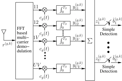
[image:3.612.80.285.348.484.2]
Fig. 2: Receiver schematic of thekth DL user in thegth user-group.
The receiver structure of thekth DL user in thegth group is shown in Fig. 2, where multicarrier demodulation is carried out with the aid of the fast Fourier transform (FFT). The resultant output signals are processed by a bank ofU V MFs associated with the spreading
code cg(t), which provide U V observations. Finally, for each of theU bits, say b(ug,k), the V observations corresponding to theV subcarriers conveyingb(ug,k)are combined, in order to generate the decision variablezu(g,k) forb(ug,k).
According to the above discussions and remembering that theG
number of T-domain spreading codes and the different subcarrier signals are orthogonal, it can be shown that the MF’s output corre-sponding to theuvth subcarrier of the reference user can be expressed as
yuv= 2P V L
K
k=1 ¯ hTuvW
(g,k) p(uvg,k)b
(g,k) u +nuv
= 2P L V
K
k=1
h(uvg,k)Tpuv(g,k)b(ug,k)+nuv, (12)
where the elements inh(uvg,k)are given by (10), while the Gaussian noise samplenuvis given by
nuv= 1 Ts
Ts
0
nuv(t)cg(t) exp (−j2πfuvt)dt, (13)
which has a zero mean and a variance ofσ2
n/Tsper dimension. Finally, the decision variable forb(ug,1)can be expressed as
zu= V
v=1
yuv, (14)
andb(ug,1)is decided according to
ˆb(g,1)
u =sgn(<(zu)), u= 1,2, . . . , U, (15) where<(z)represents the real part ofz.
According to the detection scheme of Fig. 2, the detector consists of a bank of MFs and hence has an extremely low-complexity. Furthermore, as seen in (12), the detector’s output is free from multicarrier interference. Furthermore, no MUI is imposed by the users in the other groups. However, when the array vectors of the users in the same group are non-orthogonal, these users may interfere with each other, yielding intra-group MUI. In the next section we will show that the intra-group MUI can be removed with the aid of SVD-assisted transmitter preprocessing.
III. TRANSMITTERPREPROCESSINGBASED ONSINGULAR VALUEDECOMPOSITION
In this section we consider the design of the proposed transmitter preprocessing vector p(uvg,k) seen in (12), so as to achieve two simultaneous design objectives, namely that of removing the intra-group MUI and achieving a transmit diversity order ofnt in the S-domain. We commence by expressing the preprocessing vectorp(uvg,k) as
p(uvg,k)=P (g,k) uv d
(g,k)
uv , (16)
whereP(uvg,k)is(M×nt)-dimensional, which is designed to suppress the intra-group MUI, whiled(uvg,k) is an nt-length vector used for combining the resultant signals in the S-domain, in order to achieve a diversity order of nt in the S-domain. Let usfirst consider the design ofP(uvg,k).
A. Design ofP(uvg,k): Intra-Group MUI suppression
As shown in (12), the intra-group MUI can be entirely removed, if the constituent preprocessing matrices P(uvg,j) are chosen to satisfy
h(uvg,k)TP (g,j) uv =0
T
nt, fork6=j, (17)
where0nt is an nt-length all-zero vector. Therefore, according to
[7], the constituent preprocessing matrixP(uvg,j)of userj should lie in the null subspace determined by
H(uvg,j)T = h (g,1) uv ,· · ·,h
(g,j−1) uv ,h
(g,j+1) uv ,· · ·,h
(g,K) uv
T ,
j= 1,2, . . . , K, (18)
which is composed by the spatial signatures of the users, except for userj.
Upon carrying out the SVD ofH(uvg,j)[13], we arrive at:
Huv(g,j)=Us,uv(g,j) D(uvg,j) 0
V(s,uvg,j)H V(n,uvg,j)H
, (19)
values ofH(uvg,j),0is a((K−1)×(M−K+ 1))all-zero matrix, V(s,uvg,j)is a(M×(K−1))orthonormal matrix corresponding to the signal subspace determined by the(K−1)interfering users, while V(n,uvg,j)is a(M×(M−K+ 1))orthonormal matrix corresponding to the orthogonal subspace ofH(uvg,j).
Letnt=M−K+ 1, wehrentrepresents the transmit diversity order achieved by the MC DS-CDMA system in the S-domain. Hence,ntis referred to as the effective number of transmit antennas. In this case, the constituent preprocessing matrix P(uvg,j) can be chosen as
Puv(g,j)=Vn,uv(g,j), j= 1,2, . . . , K. (20)
Let us now consider the design of the constituent preprocessing matrixd(uvg,k) in (16).
B. Design ofd(uvg,k): Transmit Diversity Combining
Upon substituting the preprocessing matrices p(uvg,j) of (16) associated with the constituent preprocessing matrices P(uvg,j) of (20) into (12), it can be shown that the intra-group MUI imposed on user 1 is entirely removed. Furthermore, the reference user’s signal is projected onto annt-dimensional orthogonal subspace. Let
e(uvg,1)=P (g,1)T uv h
(g,1)
uv , (21)
wheree(uvg,1)can be expressed as
e(uvg,1)= e (g,1) uv,1 · · · e
(g,1) uv,nt
T
. (22)
Consequently, we can express the constituent preprocessing matrix d(uvg,1)as
d(uvg,1)= d (g,1) uv,1, d
(g,1) uv,2, . . . , d
(g,1) uv,nt
T
(23)
and letd(uv,ig,1) be formulated as
duv,i(g,1)=euv,i(g,1)∗/ Euv(g,1), (24)
where e(uv,ig,1)∗ is the conjugate of e (g,1)
uv,i. Furthermore, we stipulate that
Euv(g,1)= nt
i=1 e(uv,ig,1)
2
(25)
in order to ensure that the total power transmitted to a remote user remains the same both before and after preprocessing.
Finally, upon substituting (16) associated with the constituent preprocessing matrices P(uvg,j) of (20) andd(uvg,1)of (23) into (12), it can be shown that the decision variable ofb(ug,1), u= 1, . . . , U of the reference user can be expressed as
yuv= 2P L
V E
(g,k)
uv b(uvg,k)+nuv,
u= 1, . . . , U; v= 1, . . . , V, (26)
which is free from inter-group interference, multicarrier interference and intra-group MUI.
C. Discussion
It is widely recognized that in a conventional single-carrier DS-CDMA system [3] using Ne-chip Walsh-Hadamard (WH) codes as the T-domain spreading sequences, the maximum number of users supported is K = Ne, if no BER degradation is tolerated in comparison to the corresponding single-user DS-CDMA system
having the same bandwidth. By contrast, the MC DS-CDMA system considered in this contribution has the following characteristics.
• The achievable diversity order isV nt=V(M−K+ 1), where V represents that in the F-domain, whilentis the diversity order in the S-domain;
• The number of users supported isK= NeK, 1≤K ≤ M, where Ne is the length of the T-domain spreading sequences, whileK is the number of users per user-group. With the aid of the transmitter preprocessing proposed in Sections A and III-B,K=NeKnumber of users can be supported by the MC DS-CDMA system without any significant performance degradation in comparison to the identical-bandwidth single-user MC DS-CDMA system;
• There is a trade-off between the number of users supported
and the diversity order achieved. In the extreme case, when the diversity order isV corresponding to nt =M−K+ 1 = 1, which impliesK=M, the number of supportable users is as
high asK=NeM. If the MC DS-CDMA system supports only K=Neusers, implying that each group has onlyK= 1user, then the diversity order achieved isV nt=V M.
Let us now consider our simulation results in the next section.
IV. SIMULATIONRESULT
In this section the BER performance of the MC DS-CDMA system using multiple BS transmit antenna arrays is investigated, when assuming that each subcarrier signal experiencesflat Rayleigh fading. In our simulations we assumed that the F-domain diversity order is
V = 4and that the T-domain spreading sequences were theNe= 32 -length WH codes. The BER performance of MC DS-CDMA using the proposed transmitter preprocessing scheme is also compared to that of other MC DS-CDMA systems investigated in the literature, as detailed in our forthcoming discourse.
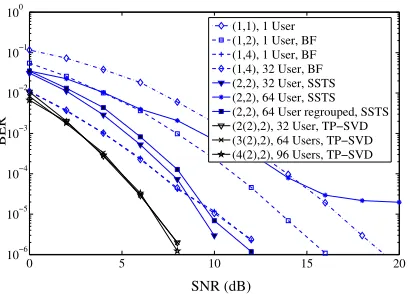
The legends used in Figs. 3 and 4 are as follows. For MC DS-CDMA using SVD-assisted transmitter preprocessing, the corre-sponding BER curves are indicated by ‘(M(nt)×L)TP-SVD’, where
Mis the number of transmit antenna arrays,Lis the number of array elements of each antenna array andntrepresents the effective number of logical transmit antennas. In Figs. 3 and 4 the legend ‘(1,1)’ indicates the MC DS-CDMA system using no preprocessing, ‘(1, L) BF’ corresponds to the MC DS-CDMA system using only the steered beamforming scheme of [5], while ‘(M, L) SSTS’ corresponds to MC DS-CDMA system using both steered beamforming and space-time spreading (STS) [3], which are not detailed here owing to lack of space.
It is observed from the results seen in Figs. 3 and 4 that when assuming orthogonal multicarrier signals and that the subcarrier signals experience flat-fading, conventional MC DS-CDMA using
0 5 10 15 20 10−6
10−5 10−4 10−3 10−2 10−1 100
SNR (dB)
BER
[image:5.612.78.283.71.218.2](1,1), 1 User (1,2), 1 User, BF (1,4), 1 User, BF (1,4), 32 User, BF (2,2), 32 User, SSTS (2,2), 64 User, SSTS (2,2), 64 User regrouped, SSTS (2(2),2), 32 User, TP−SVD (3(2),2), 64 Users, TP−SVD (4(2),2), 96 Users, TP−SVD
Fig. 3: BER versus SNR performance of the DL MC DS-CDMA system usingV = 4subcarriers andNe= 32-chip WH code based T-domain spreading.
0 5 10 15 20
10−6 10−5 10−4 10−3 10−2 10−1 100
SNR (dB)
BER
[image:5.612.74.282.281.421.2](2,2), 32 User, SSTS (2,3), 32 User, SSTS (2,3), 64 User, SSTS (2,3), 64 User regrouped, SSTS (4,2), 32 User, SSTS (3(2),2), 64 User, TP−SVD (3(2),3), 64 User, TP−SVD (4(3),2), 64 User, TP−SVD (4(3),3), 64 User, TP−SVD
Fig. 4: BER versus SNR performance of the DL MC DS-CDMA systems using V = 4 subcarriers andNe = 32-chip WH codes based T-domain spreading.
We can also infer the following observations from the results of Figs. 3 and 4. Firstly, when the MC DS-CDMA system employs only a single transmit antenna array (M = 1) using a single array element (L = 1), the attainable BER performance is the worst. Secondly, when the MC DS-CDMA system employs M = 1 BS antenna arrays, but L > 1 array elements, the required SNR is significantly reduced and the corresponding curves are shifted to the left of that corresponding to the case of L= 1. Thirdly, when the MC DS-CDMA system employs M > 1 BS antenna arrays and each antenna array hasL >1array elements, and when additionaly steered transmitter beamforming combined with STS is applied, the MC DS-CDMA system becomes capable of achieving a transmit diversity order of M, in addition to the SNR reduction achieved by the antenna arrays [5]. Furthermore, as seen in Figs. 3 and 4, when the MC DS-CDMA BS transmitter employs our SVD-assisted transmitter preprocessing scheme denoted by ‘TP-SVD’, the BER performance is further improved in comparison to the system using pure SSTS in isolation. In contrast to the pure SSTS scheme [5], which does not require the explicit knowledge of the DL CIRs, except for the DoAs necessitated by the steered beamforming scheme, SVD-assisted transmitter preprocessing requires the explicit knowledge of the DL CIRs. However, the SSTS-assisted transmitter scheme
typically employs a higher-complexity multiuser detection (MUD) scheme, than SVD-assisted transmitter preprocessing, which requires only low-complexity MF-assisted detection.
V. CONCLUSION
In this contribution we have proposed and investigated a SVD-assisted transmitter preprocessing scheme designed for MC DS-CDMA systems using multiple BS transmit antenna arrays, where each antenna array employs multiple array elements. The SVD-assisted transmitter preprocessing scheme has been designed for supporting the highest possible number of downlink users, while simultaneously achieving the highest possible transmit diversity gain. Our study shows that for a SVD-assisted MC DS-CDMA system usingMtransmit antenna arrays and length-NeT-domain spreading sequences, the number of users supported with the aid of both T-domain and S-domain multiplexing can be as high as M Ne . Our simulation results show that the SVD-assisted MC DS-CDMA system is indeed capable of supporting a high number of users, while maintaining a near-single-user BER performance.
REFERENCES
[1] L. L. Yang and L. Hanzo, “Multicarrier DS-CDMA: A multiple-access scheme for ubiquitous broadband wireless communications,”IEEE Com-munications Magazine, vol. 41, no. 10, pp. 116–124, October 2003. [2] L.-L. Yang and L. Hanzo, “Performance of generalized multicarrier
DS-CDMA over Nakagami-mfading channels,”IEEE Transactions on Communications, vol. 50, pp. 956 – 966, June 2002.
[3] L.Hanzo, L.-L. Yang, E.-L. Kuan, and K.Yen,Single- and Multi-Carrier DS-CDMA Multi-User Detection, Space-Time Spreading, Synchronisa-tion and Standards. Chichester, UK: John Wiley and Sons, Ltd, 2003. [4] B. Hu, L.-L. Yang, and L. Hanzo, “Performance of the smart antenna aided multicarrier DS-CDMA uplink,” inIEEE 60th Vehicular Technol-ogy Conference. IEEE, September 2004, pp. 191 – 195.
[5] B. Hu, L.-L. Yang, and L.Hanzo, “Performance of the smart antenna aided generalized multicarrier DS-CDMA downlink using both time-domain spreading and steered space-time spreading,”IEEE 62nd Ve-hicular Technology Conference,, vol. 1, no. 28-25, pp. 458–462, Sept. 2005.
[6] S. Verdu,Multiuser Detection. Cambridge University Press, 1998. [7] L.-U. Choi and R. Murch, “A transmit preprocessing technique for
multiuser MIMO systems using a decomposition approach,”IEEE Trans-actions on Wireless Communications, vol. 3, no. 1, pp. 20 – 24, 2004. [8] R. L.-U. Choi and R. D. Murch, “New transmit schemes and simplified
receivers for MIMO wireless communication systems,” IEEE Trans-actions on Wireless Communications, vol. 2, no. 6, pp. 1217–1230, November 2003.
[9] R. L.-U. Choi, M.T. Ivrlac, R. D. Murch, and W. Utschick, “On strategies of multiuser MIMO transmit signal processing,”IEEE Transactions on Wireless Communications, vol. 3, no. 6, pp. 1936–1941, November 2004. [10] R. L.-U. Choi and R. D. Murch, “A pre-BLAST-DFE technique for the downlink of frequency-selective fading MIMO channels,” IEEE Transactions on Communications, vol. 52, no. 5, pp. 737–743, May 2004.
[11] ——, “A transmit MIMO scheme with frequency domain pre-equalization for wireless frequency selective channels,”IEEE Transac-tions on CommunicaTransac-tions, vol. 3, no. 3, pp. 929–938, May 2004. [12] ——, “Transmit-preprocessing techniques with simplified receivers for
the downlink of MISO TDD-CDMA systems,”IEEE Transactions on Vehicular Technology, vol. 53, no. 2, pp. 285–295, March 2004. [13] S. Haykin,Adaptive Filter Theory, 3rd ed. Upper Saddle River, New