City, University of London Institutional Repository
Citation
:
Bianchi, G., Kovacevic, A., Cipollone, R., Murgia, S. and Contaldi, G. (2016).
Development of a general numerical methodology for CFD analyses in sliding vane
machines and application on a mid-size oil injected air compressor. Paper presented at the
23rd International Compressor Engineering Conference, 11-14 Jul 2016, Indiana, USA.
This is the accepted version of the paper.
This version of the publication may differ from the final published
version.
Permanent repository link:
http://openaccess.city.ac.uk/15132/
Link to published version
:
Copyright and reuse:
City Research Online aims to make research
outputs of City, University of London available to a wider audience.
Copyright and Moral Rights remain with the author(s) and/or copyright
holders. URLs from City Research Online may be freely distributed and
linked to.
City Research Online:
http://openaccess.city.ac.uk/
[email protected]
1343
Page 1
Development of a general numerical methodology for CFD analyses in sliding vane
machines and application on a mid-size oil injected air compressor
Giuseppe BIANCHI
1,2*, Sham RANE
2, Ahmed KOVACEVIC
2,
Roberto CIPOLLONE
1, Stefano MURGIA
3, Giulio CONTALDI
31
University of L’Aquila,
Department of Industrial and Information Engineering and Economics,
L’Aquila, Italy
([email protected], [email protected])
2
City University London,
Centre for Compressor Technology,
London, United Kingdom
([email protected], [email protected])
3
Ing. Enea Mattei S.p.A.,
Vimodrone, Italy
([email protected], [email protected])
* Corresponding Author
ABSTRACT
The current work presents the development of a numerical methodology to investigate sliding vane rotary machines by means of advanced design tools such as the Computational Fluid Dynamics ones. Although highly limited in this topic, literature shows that the major constraint for the employment of such approaches is the deformation and motion of the rotor mesh, i.e. the computational grid related to the fluid volume between stator, rotor and blades of the positive displacement vane device. To address these issues, a novel grid generation approach is herein proposed and accomplished through a series of steps: geometrical 2D modeling of the machine cross section profile, boundary generation of the rotor mesh and, eventually, distribution of computational nodes using algebraic algorithms with transfinite interpolation, post orthogonalization and smoothing. This methodology was subsequently tested on an industrial vane compressor comparing the results of oil free and oil injected simulations set up in the ANSYS CFX solver. Results show angular pressure evolution inside the compressor vanes, a recirculation region induced by the clearance between the vane tip and the stator as well as the cooling effects of the oil entrained in the cells during the compression phase.
1.
INTRODUCTION
Compressed air is an indispensable utility and, at the same time, one of the factors that highly affects the energy costs of industrial facilities. On a global scale, compressed air production accounts for 4.2% of electricity consumptions, 710 Mtonne/yr in absolute terms (IEA, 2015). In order to lower this share and the corresponding CO2
emissions, the scientific and industrial communities have been developing energy saving and recovery strategies in compressed air systems. In particular, it has been estimated that more efficient compressors might contribute for up to 10% of the energy saving potential (Saidur et al., 2010). Although current air compressor market for industrial applications is led by screw machines, other positive displacement technologies are also available. Among them, sliding vane rotary compressors benefit of intrinsic geometrical and operating features that might forecast a breakthrough in compressed air systems.
1343
Page 2
performed a series of studies concerned to the development of a comprehensive modeling approach for sliding vane expanders including geometry, vane kinematics, blade dynamics and friction phenomena as well as energy balances. Modeling and experimental studies in steady state conditions were also carried out by Tramschek and Mkumbwa (1996) on circular vane compressors using radial and non-radial blade arrangements inside the rotor slots. Additionally, Al-Hawaj (2009) modeled a dual stage elliptical sliding vane compressor for refrigeration applications. Bianchi and Cipollone (2015a, 2015b) eventually presented comprehensive numerical and experimental methodologies to address mechanical and thermodynamic improvements in sliding vane machines, with particular focus on air compressors.
The modeling approaches proposed in all the above mentioned research works mostly belong to lumped parameters or one-dimensional (1D) categories. These simplified methods assume uniform or 1D spatial distributions of the physical quantities involved during mass and energy exchanges that highly reduce the computational cost of the simulation. However, they are not able to represent real machine geometry and effects like fluid leakages which are of foremost importance in devices like positive displacement machines. Furthermore, although the experimental validation of these mathematical models allowed to address and estimate further performance improvements of industrial machines, zero and one-dimensional approaches are not suitable to detect failures on existing devices or to properly support the development of future sliding vane prototypes at an industrial level. In order to accomplish studies of greater complexity and accuracy on real industrial products, very recently scientists from academia and industry started to employ state of the art Computational Fluid Dynamics (CFD) tools on sliding vane machines, namely expanders for energy recovery systems based on Organic Rankine Cycles (ORC) and automotive oil pumps. Montenegro et al. (2014), investigated a sliding vane ORC expander with elliptic stator and working with R245fa using the OpenFOAM CFD solver. Due to the lack of an automatic grid generator, the vane mesh was created relying upon the built-in Cartesian mesh tool in OpenFOAM. To speed up the computations, the momentum equation was modified by the introduction of a Darcy-Forchheimer type source term, which takes into account both the viscous and inertial effects occurring in a tiny gap; this resistance source term was locally applied only on the cells located at the flat shaped vane tip. Discrepancies on the output power were up to 12%.
Kolasiński and Błasiak (2015) performed experimental and numerical studies on a micro ORC sliding vane expander with maximum power of 600W using R123. In their modeling activity, to avoid negative volumes in the mesh, the expander geometry was modified reducing vane thickness and increasing the vane tip clearance, whose profile was still flat. This latter adjustment yielded to a modified eccentricity. Movement and deformation of the vane grid were accomplished using an embedded tool of ANSYS suite. In particular, internal vane nodes were relocated according to a displacement diffusion model.
1343
Page 3
to retrieve remarkable information on the flow field developing inside the compressor vane throughout the whole operation of the machine.
2.
GEOMETRICAL MODELING
In geometrical terms, the core of a sliding vane machine is essentially composed of two cylinders which are eccentrically mounted one inside the other and tangent along a generatrix. The inner cylinder has a circular cross section and presents a series of slots that host an equal number of parallelepipedic blades. The outer cylinder may even have an elliptical cross section and it usually is a motionless component called stator, unlike the inner one that rotates around its axis and it is consequently called rotor. As the inner cylinder rotates, the blades slide along the rotor slots and build up the cells, whose volume changes over a full revolution because of the mounting eccentricity. To minimize friction losses, blade tip usually has a circular profile with circle center on the blade axis such that the contact between blades and stator theoretically occurs along a single generatrix.
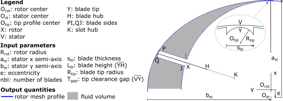
[image:4.612.71.530.296.461.2]Since the core of a sliding vane machine has a constant cross section profile with respect to the rotation axis, the boundaries of the fluid volume enclosed in the core were parameterized using an analytical bi-dimensional (2D) modeling approach that tracks the trajectories of all the relevant points displayed in Figure 1. This method, proposed in Bianchi and Cipollone (2015a), was herein improved to account for finite blade thickness and circular blade tip profile.
Figure 1: Schematics of the parametric geometrical modeling for sliding vane machines with inputs and outputs
A major assumption in the 2D modeling of the sliding vane machine core and, in turn, in the resulting rotor grid was to consider a constant minimum clearance between blade tip and stator along a full vane revolution. The minimum tip clearance gap is shown in Figure 1 as Tgap. This choice is a trade-off between the ideal tangency described above
and real operating conditions, whereas blades’ tips slide along a fluid layer (usually oil) that prevents a dry contact with the stator. The first limiting case would have indeed prevented the usage of a single rotor O-grid while the calculation of the instantaneous minimum liquid film thickness between blade tip and stator would have required either the usage of simplified hydrodynamic approaches, as the one in Bianchi and Cipollone (2015a), or complex fluid-structure computations. Additionally, any leakage phenomenon between consecutive vanes at the clearance between rotor slots and blade walls as well as the ones occurring across the end wall plates were neglected due to the tight gaps and slow flow velocities at those locations.
The resulting 2D boundary of the fluid volume enclosed in the core of a sliding vane machine is eventually composed of the stator profile, and the rotor profile with all the blades outside the rotor slots such that the minim gap between blades’ tips and the stator occurs only once per tip.
3.
GRID GENERATION AND MOTION
1343
Page 4
[image:5.612.79.538.212.330.2]as the leakage volume. Even though the change in volume of this gap is very small compared to the core region, because of the eccentricity between rotor and stator, the relative shape of these gaps change with rotor positions. The topology of each compression chamber and every connecting leakage gap is a rectangle in the computational domain. Figure 2 shows the domain transformations for the core and the leakage areas when they are treated separately. Although several algorithms for the structured meshing of such rectangular domains are available in practice, Kovacevic et al. (2007) showed that algebraic algorithms with transfinite interpolation, post orthogonalization and smoothing are the most efficient ones for applications like twin screw compressors where a number of mesh files are required to be generated and supplied to the CFD solvers in order to treat mesh deformation. Similar algebraic grid generation principle was used in this work for the vane compressor rotor domain mesh.
Figure 2: Domain transformation from the core region to computational region and then to the grid
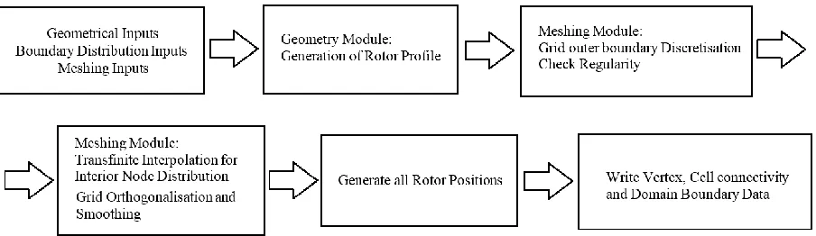
Flow chart in Figure 3 lists the main stages of the grid generation procedure. The geometry program described in Section 2 is used to produce the rotor profile along with the vane at the initial rotor position. This forms an input to the meshing algorithm. Successive rotor positions appear to be rigid body rotations for the rotor while for the fluid volume that is deforming, it is a complex boundary motion where rotor rotates, stator is stationary and each of the vane is undergoing a general body motion. For simplification, blade tip clearance gap changes were not accounted in the presented analysis, but the meshing algorithm allows the possibility to further introduce a gap variation function.
Figure 3: Vane compressor mesh generation procedure
[image:5.612.83.535.456.587.2]1343
Page 5
Figure 4: Boundary discretization as an ‘O’ Grid and transition function
At the position where the core region topology does not remain rectangular, as it happens when the vane slides inside the rotor, a simplification was introduced to convert the vane side walls into short segments on the rotor surface. This is seen in the view B of Figure 4 and it is anticipated that the leakage flow will not be influenced by this simplification as the gap clearance does not change. Nevertheless, this will have an influence on the solver stability due to sudden change in topology and could demand higher solver relaxation parameters.
[image:6.612.74.537.491.698.2]1343
Page 6
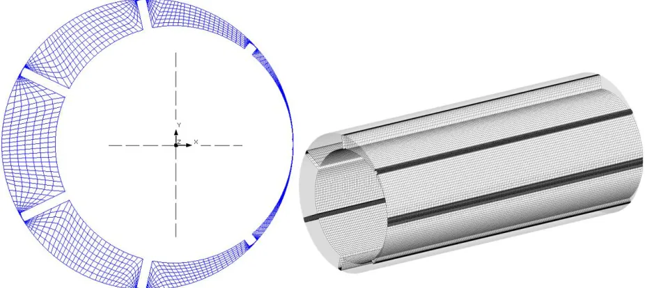
The second stage in mesh generation is distribution of interior nodes. Transfinite interpolation, orthogonalization and smoothing as described in Kovacevic et al. (2005) were used in these procedures to get a good quality hexahedral cell structure. Once the 2D mesh is generated for all rotor positions, the mesh is assembled into 3D volume in the required format of the solver (Figure 5). In the current implementation there is possibility to export the mesh in solvers such as ANSYS CFX, ANSYS FLUENT, STAR CCM+ and Simerics PumpLinx. The entire meshing procedure was implemented in the software package SCORG™ developed at City University London. The rotor domain is eventually connected to suction and discharge ports via non-conformal interfaces, as usually occurs in CFD analysis on positive displacement machines (Kovacevic et al., 2005). Ports meshing is usually carried out using standard tools and with reference to a tetrahedral cell structure to better capture the real geometry.
In the presented analysis, ANSYS CFX solver was used to calculate the oil free and oil injected flow fields in the compressor. This solver was selected mainly because of the Authors’ experience gained with oil injected twin screw machines. In particular, ANSYS CFX provides a model called Junction Box Routine that is a user defined library to specify mesh deformation from custom applications such as SCORG. The solver updates the nodes coordinates from set of pre-generated files after every crank angle step (or its submultiples). Time step finally results from crank angle step and revolution speed.
4.
TEST CASE
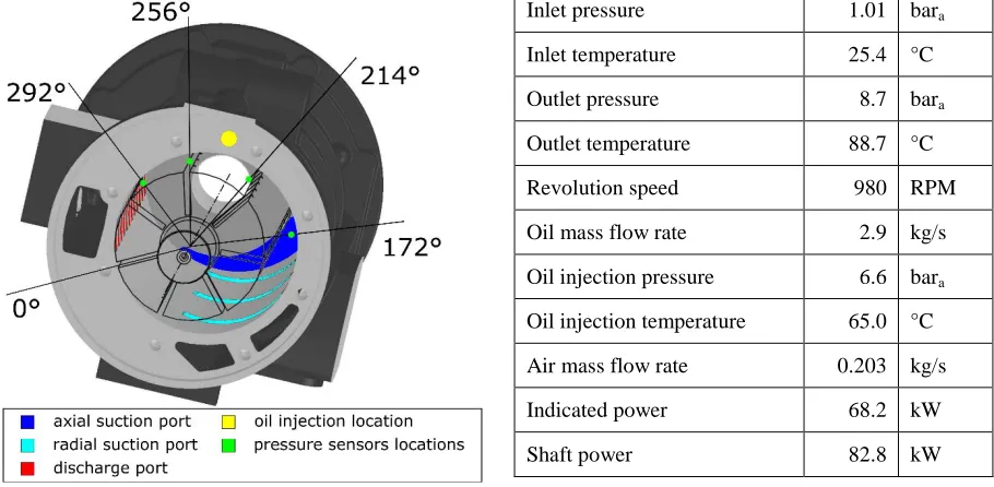
As reference application to test the numerical methodology just presented, an industrial mid-size oil injected air compressor was considered. As shown in Figure 6, in this machine the suction process occurs both through axial and radial ports: the first ones are located on the end wall plates of the compressor while the radial suction port is composed of three slanted slots along the stator. On the other hand, the discharge process takes place only through a series of radial slots located on the stator. At a specified position of the rotor and compression process, oil is injected in the compressor cells through a series of calibrated orifices displaced along the axial direction of the machine and fed by a common rail whose cross section is represented by the yellow dot in Figure 6. The operating conditions that were considered as benchmark for the numerical results were 980 RPM as revolution speed and 8.7 bara as outlet
pressure (Table 1).
4.1 Experimental setup
The compressor was instrumented with pressure, temperature and flow rate sensors across the machine and along the oil injection circuit. Furthermore, a torque meter allowed to retrieve the mechanical power while a set of four piezoelectric pressure transducers were installed along the compression and the discharge phases. On the other hand, intake process was reasonably considered as isobaric. The in-vane pressure data were processed according to the methodology proposed in Bianchi and Cipollone (2015b) and allowed to reconstruct the indicator diagram of the
Inlet pressure 1.01 bara
Inlet temperature 25.4 °C
Outlet pressure 8.7 bara
Outlet temperature 88.7 °C
Revolution speed 980 RPM
Oil mass flow rate 2.9 kg/s
Oil injection pressure 6.6 bara
Oil injection temperature 65.0 °C
Air mass flow rate 0.203 kg/s
Indicated power 68.2 kW
Shaft power 82.8 kW
[image:7.612.74.529.393.616.2]Figure 6: Reference sliding vane compressor with indication of ports and sensors locations
1343
Page 7
compressor and, in turn, to calculate the indicator power which is listed in Table 1 together with all the quantities measured.
4.2 Numerical setup
In order to evaluate the sealing effect of the oil, two compressor configurations were considered, namely oil free and oil injected. In its complete layout, the computational domain was composed of four main zones: suction line, rotor mesh, oil rail and discharge line. Grids’ sizes, expressed in terms of millions of cells, are 1.4, 0.3, 0.2 and 0.4 respectively. As shown in Figure 7, the first and latter domains not only include axial or radial ports but also the intake valve and the discharge pipe. Apart from fluid domain enclosed among stator, rotor and blades, all the fluid zones were retrieved using CAD models of the industrial machine and were further discretized using tetrahedrons. On the other hand, the grid generation of the rotor mesh was accomplished using the methodology presented in the previous sections and with reference to actual machine geometry but using a conservative value for the minimum tip clearance gap (Tgap) of 200 μm.
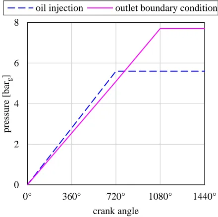
[image:8.612.69.536.325.578.2]ANSYS CFX is a pressure based coupled CFD solver. Air was modeled as ideal gas while oil as a fluid whose thermophysical properties were customized with reference to proprietary data. Pressure boundary conditions were considered both at air and oil inlets as well as at the compressor outlet. The specification of pressure at the discharge boundary and at the oil injection rail is a major factor influencing the numerical stability of the solver. Hence time dependent functions were used to gradually ramp the boundary pressure as shown in Figure 8. Mass and energy exchanges between fixed and rotating grids occurred through non-conformal sliding interfaces circumferentially located along the stator surface (e.g. suction and discharge ports as well as oil orifices) or on the end wall plates for the axial suction ports.
[image:8.612.70.297.329.544.2]Figure 7: Tetrahedral mesh in the Suction and Discharge lines
Figure 8: Discharge Boundary and Oil Injection Pressure ramp functions
5.
RESULTS
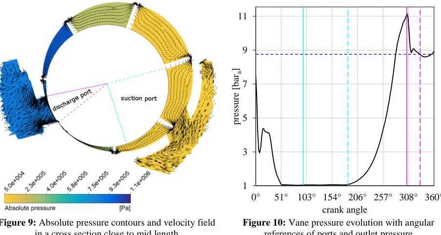
A first attempt in the numerical investigation of the sliding vane air compressor was performed considering a set of single phase simulations, whereas air was solely taken into account. Results of these calculations after 3 full revolutions are presented in Figures 9 and 10. In particular, Figure 9 reports the pressure contours in a cross section of the machine close to mid length, namely at 285 mm with respect to a full axial length of 540 mm. In this Figure, velocity field is additionally superimposed and normalized. A virtual pressure probe rotating with the vane further allowed to retrieve the angular pressure evolution over a full cycle that is reported in Figure 10. The x-axis of this Figure has been intentionally divided in 7 ranges in order to be in perfect agreement with Figure 9. Angular displacements of intake and discharge ports are reported in both Figures with cyan and magenta lines while dashed blue line in Figure 10 indicates the experimental outlet pressure and, in turn, the outlet boundary condition after the
0 2 4 6 8
0° 360° 720° 1080° 1440°
p
ress
u
re
[b
arg
]
crank angle
[image:8.612.312.532.331.550.2]1343
Page 8
[image:9.612.76.528.245.486.2]ramp initialization. Due to the relatively large gap at the tip clearance, a strong backflow could be noticed between the discharge phase and the suction process. Indeed, the clearance at the tangency between stator and rotor (0° in Figure 10) acts as an orifice which drops the pressure inside the first vane from the discharge value to more than 3 bar. The vane volume increase from the first to the second vane and its interaction with the suction port further contribute to expand the fluid up to the inlet pressure. Nevertheless, the temperature level of the backflow driving the expanded air inside the suction ports is greater than the fresh charge coming from the inlet and mixes with it as occurs in Figure 13, but with a less relevant extent, for the oil-injected case. In turn, the starting temperature of the compression process, that takes place from 186° to 305°, leads the fluid to an over-compression up to 11 bar before being suddenly damped as the discharge begins. This trend is in disagreement with the experimental one which did not show any over-compression. Furthermore, the backflow towards the suction ports led to a mass unbalance in the simulations even though the pressure coupled solver handled the continuity equation in direct way. These remarks contribute to state the need of taking into account the oil presence in the simulations but, more importantly, show that oil injection in sliding vane air compressors is indispensable for sealing across any clearance. Moreover, additional features of the lubricant injection are friction power reduction and air cooling.
Figure 9: Absolute pressure contours and velocity field in a cross section close to mid length
Figure 10: Vane pressure evolution with angular references of ports and outlet pressure
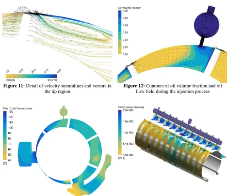
Figure 11 presents a detailed view of the air velocity field across the tip region in oil injected simulations with reference to the vane downstream the oil injection process (206°-257°). Despite the sealing action of the lubricant, the clearance at the vane tip induces a backflow driven by adverse pressure gradient in opposite direction to the counter clockwise revolution speed sense. In turn, the overall flow field in the compressor vane is affected by a recirculation region whose magnitude is gradually lowered as the leakage flow interacts with the main one (which is aligned with the rotation sense). This phenomenon contributes to enhance the heat transfer between the compressing air and the oil that, after the radial injection shown in Figure 12, spreads along the leading side of the vane and mixes with air. The oil accumulation on the walls of the rotor grid, i.e. on the metallic surfaces which define the vane in reality, can be seen in the bottom left of Figure 12. These oil layers allow to lower friction losses between surfaces in relative motion, namely stator with blade tip and blade side walls with rotor slots.
The cooling effect of the oil is additionally noticeable in Figure 13, which reports the total temperature contours in the same mid cross section at 285 mm. The temperature increase during the first stages of the compression process is indeed mitigated in the vane where the oil supply takes place. Nevertheless, as the compression proceeds, air temperature keeps increasing up to 100 °C-120 °C, as it can be seen in cell whose angular range is 257°-308°. Finally, at the discharge manifold, an intense heat transfer takes place and leads the temperature of the air-oil mixture back to 90 °C.
The thermal power gained by the lubricant during the convective heat transfer with air increases oil temperature and, in turn, lowers its viscosity. This phenomenon is presented in Figure 14 using an isosurface of points having an oil
1 3 5 7 9 11
0° 51° 103° 154° 206° 257° 308° 360°
p
ress
u
re
[b
ara
]
1343
Page 9
[image:10.612.67.535.145.550.2]volume fraction equal to 2.5%. The variation of oil dynamic viscosity along the axial direction is essentially due to discrepancies in oil flow rate supplied by each injector because of the single central point inlet. Hence, air cooling is more effective in the central region of the compressor core. On a global scale, oil dynamic viscosity at the discharge phase has lowered 4.4 times with respect to the value at the injection. This effect has a detrimental drawback in the hydrodynamic capabilities that the oil layer must have to sustain the blade tip and to prevent any dry contact with the stator surface.
[image:10.612.73.531.360.545.2]Figure 11: Detail of velocity streamlines and vectors in the tip region
Figure 12: Contours of oil volume fraction and oil flow field during the injection process
Figure 13: Air total temperature contours in a cross section close to mid length
Figure 14: Variation of oil dynamic viscosity along an isosurface having a volume fraction of 2.5%
6.
CONCLUSIONS
1343
Page 10
clearance between stator and blades’ tips. These phenomena were particularly severe when the vane was approaching the tangency region between rotor and stator. Large backflows at high pressure and temperature indeed destabilized the mass balance and led to an over-compression not revealed experimentally. Three-dimensional transient multiphase simulations were consequently performed to take into account the injection of oil during the compression process. This upgrade allowed to track a recirculation region induced in the vane flow field by the leakage flow through the clearance at the tip. Furthermore, the convective heat transfer with air showed the cooling capabilities of the lubricant even when supplied into the vanes as liquid jets. On the other hand, the oil temperature rise decreased its dynamic viscosity and, in turn, its hydrodynamic potential to prevent dry contact between blades and stator. The effects of a variable tip clearance due to oil temperature and blade dynamics will be taken into account in future upgrades of the numerical methodology.
REFERENCES
O. Al-Hawaj (2009), Theoretical modeling of sliding vane compressor with leakage, International Journal of Refrigeration, Volume 32, Issue 7, Pages 1555-1562, ISSN 0140-7007, DOI:10.1016/j.ijrefrig.2009.07.005. ANSYS 14.0 (2011), ANSYS CFX Manual
O. Badr, P.W. O'Callaghan, S.D. Probert, (1985a), Multi-vane expanders: Geometry and vane kinematics, Applied Energy, Volume 19, Issue 3, Pages 159-182, ISSN 0306-2619, DOI:10.1016/0306-2619(85)90006-6.
O. Badr, S.D. Probert, P. O'Callaghan, (1985b), Multi-vane expanders: Vane dynamics and friction losses, Applied Energy, Volume 20, Issue 4, Pages 253-285, ISSN 0306-2619, DOI:10.1016/0306-2619(85)90018-2.
G. Bianchi and R. Cipollone, (2015a), Theoretical modeling and experimental investigations for the improvement of the mechanical efficiency in sliding vane rotary compressors, Applied Energy, Volume 142, Pages 95-107, ISSN 0306-2619, DOI: 10.1016/j.apenergy.2014.12.055
G. Bianchi and R. Cipollone, (2015b), Friction power modeling and measurements in sliding vane rotary compressors, Applied Thermal Engineering, Volume 84, Pages 276-285, ISSN 1359-4311, DOI: 10.1016/j.applthermaleng.2015.01.080
International Energy Agency (IEA), (2015), Key world energy statistics, 2015.
A. Kovacevic, (2005), Boundary adaptation in grid generation for CFD analysis of screw compressors, International Journal for Numerical Methods in Engineering Volume 64, Issue 3, Pages 401–426, DOI: 10.1002/nme.1376 A. Kovacevic and N. Stosic and I. Smith, (2007), Screw Compressors - Three Dimensional Computational Fluid
Dynamics and Solid Fluid Interaction, Springer-Verlag Berlin Heidelberg, New York, ISBN 3-540-36302-5. P. Kolasiński and P. Błasiak, (2015), Numerical and experimental investigation on the rotary vane expander
operation in micro ORC system, 3rd International Seminar on ORC Power Systems, Brussels, Belgium
G. Montenegro and A. Torre et al., (2014), Evaluating the Performance of a Rotary Vane Expander for Small Scale Organic Rankine Cycles Using CFD tools, Energy Procedia, Volume 45, Pages 1136-1145, ISSN 1876-6102, DOI:10.1016/j.egypro.2014.01.119.
Prasad, B. G. Shiva, (2004), CFD for Positive Displacement Compressors, International Compressor Engineering Conference at Purdue University, West-Lafayette (IN), United States, URL: docs.lib.purdue.edu/icec/1689/ S. Rane, A. Kovacevic, N. Stosic, & M. Kethidi, (2013), Grid deformation strategies for CFD analysis of screw
compressors, International Journal of Refrigeration, Volume 36, Issue 7, Pages 1883-1893, ISSN 0140-7007, DOI: 1016/j.ijrefrig.2013.04.008.
R. Saidur, N.A. Rahim, M. Hasanuzzaman, (2010), A review on compressed-air energy use and energy savings, Renewable and Sustainable Energy Reviews, Volume 14, Issue 4, Pages 1135-1153, ISSN 1364-0321, DOI: 10.1016/j.rser.2009.11.013.
Tramschek, A. B., and M. H. Mkumbwa, (1996), Mathematical modelling of radial and non-radial rotary sliding vane compressors, International Compressor Engineering Conference at Purdue University, West-Lafayette (IN), United States, URL: docs.lib.purdue.edu/icec/1151/
Q.Zhang and X. Y. Xu, (2014), Numerical Simulation on Cavitation in a Vane Pump with Moving Mesh, 5th International Conference on Computational Methods, Cambridge, England