White Rose Research Online
Universities of Leeds, Sheffield and York
http://eprints.whiterose.ac.uk/
This is an author produced version of a paper published in
Proceedings of the
ACM Symposium on Virtual Reality Software and Technology.
White Rose Research Online URL for this paper:
http://eprints.whiterose.ac.uk/4964/
Published paper
Jones, D.M., Ruddle, R.A. and Savage, J.C. (2002)
Implementing flexible rules of
interaction for object manipulation in cluttered virtual environments.
In:
Proceedings of the ACM Symposium on Virtual Reality Software and Technology.
VRST'02, November 11 - 13, 2002, Hong Kong, China. ACM , pp. 89-96.
http://dx.doi.org/10.1145/585740.585756
Implementing Flexible Rules of Interaction for
Object Manipulation in Cluttered Virtual Environments
Roy A Ruddle
Informatics Research Institute
School of Computing
University of Leeds, UK
+44 113 343 5430
[email protected]
Justin CD Savage
School of Psychology
Cardiff University, UK.
+44 292 087 4007
[email protected]
Dylan M Jones
School of Psychology
Cardiff University, UK
+44 292 087 4007
[email protected]
ABSTRACT
Object manipulation in cluttered virtual environments (VEs) brings additional challenges to the design of interaction algorithms, when compared with open virtual spaces. As the complexity of the algorithms increases so does the flexibility with which users can interact, but this is at the expense of much greater difficulties in implementation for developers. Three rules that increase the realism and flexibility of interaction are outlined: collision response, order of control, and physical compatibility. The implementation of each is described, highlighting the substantial increase in algorithm complexity that arises. Data are reported from an experiment in which participants manipulated a bulky virtual object through parts of a virtual building (the piano movers’ problem). These data illustrate the benefits to users that accrue from implementing flexible rules of interaction.
Categories and Subject Descriptors
I.3.6 [Computer Graphics]: Methodology and Techniques -
Interaction Techniques. I.3.6 [Computer Graphics]: Three-Dimensional Graphics and Realism - Virtual Reality. H.5.2 [Information Interfaces and Presentation]: User Interfaces -
Input devices and strategies.
General Terms
Algorithms, Measurement, Performance, Design, Experimentation, Human Factors.
Keywords
Virtual Environments, Object Manipulation, Rules of Interaction.
Permission to make digital or hard copies of all or part of this work for personal or classroom use is granted without fee provided that copies are not made or distributed for profit or commercial advantage and that copies bear this notice and the full citation on the first page. To copy otherwise, or republish, to post on servers or to redistribute to lists, requires prior specific permission and/or a fee.
VRST’02, November 11-13, 2002, Hong Kong. Copyright 2002 ACM 1-58113-530-0/02/0011…$5.00.
1. INTRODUCTION
Many different algorithms have been proposed for the manipulation of objects in virtual environments (VEs), and examples include arm extension techniques such as the “go-go” [9], ray casting techniques such as HOMER [1], and image plane interaction [8]. Experimental comparisons of some of these have been performed [2]. However, a limitation is that they have all been designed from the point of view of manipulating objects in open (uncluttered) virtual spaces.
A wide variety of VE applications use environments that are cluttered. These applications range from those used to design the interior layouts of buildings, to simulating the manual handling of materials in new factories (e.g., automotive), and assessing the buildability and maintainability of complex mechanical and pharmaceutical equipment. All of these types of application bring major challenges to the design of algorithms used to control interaction. First, objects must be prevented from moving through or penetrating each other. Collision detection is only part of this problem because the application must also define what happens after a collision has occurred. This latter part is termed collision response, and the algorithms available have widely-varying effects on the ease and realism with which users can interact. Second, visual continuity must be preserved, so objects don’t appear to “jump” from one position to another, especially in the aftermath of a collision. Third, interaction in cluttered VEs is characterized by movements that are small and precise, for example, avoiding an obstacle or manipulating an object through a tightly-fitting gap, and the ease with which these can be achieved is affected by the order of control that is used. Fourth, human-in-the-loop design considerations often need to be addressed, and for these it is important that users adopt postures in their VE interaction that are physically compatible with those that they would adopt when performing the task in the real world.
1.1 Interaction and Software Complexity
Interaction algorithms can be thought of as comprising a set of rules. As the number and scope of the rules is increased, users are able to interact in a much more flexible manner. This allows them to develop their own interaction strategies, and use the interface in the way that they wish, not just the way intended by the developer.implemented in a rather simplistic manner and users are left to cope as best they can.
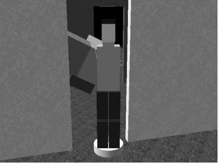
This article describes the implementation of rules that allow users to interact flexibly when manipulating objects in cluttered VEs. The article focuses on the complexity of the interface software that arises when flexible rules are implemented. The rules chosen are applicable to a wide range of application situations, but are considered here within the context of the general purpose task of moving a large object through a tightly-fitting environment, a task that is known as the piano movers’ problem. In the virtual version of the task, the user controls a virtual human (the user’s embodiment within the VE; the user “is” the virtual human) that carries an object through the VE (see Figure 1). The virtual human and object are two parts of a coupled system in which the position and orientation of both parts can be varied independently even though they remain linked together (the human grasps the object in both hands at all times).
[image:3.612.80.301.348.513.2]The task is ideally suited to studying VE manipulation because the difficulty can be increased simply by reducing the clearance between the object and the environment. As the task gets more difficult flexible rules of interaction will produce greater and greater benefits, with the benefits that accrue to users outweighing the extra demands made on developers. Following the description of the three types of rule (collision handling, order of control, and physical compatibility) the results of an experiment are reported that investigated participants’ interaction behavior when using the rules.
Figure 1. A virtual human carrying an object through one doorway of the offset VE used in the experiment. The second
doorway is beyond the human.
2. COLLISION HANDLING
Collision handling involves the detection of collisions and defining a system’s subsequent response. Collision detection is a topic that is well-researched (for a recent review, see [5]). In most VE applications the speed at which users manipulate objects is relatively slow, so polygon-polygon collision checks, carried out at the end of each graphics frame, are sufficiently accurate. Once a collision has been detected, feedback should be given to the user using visual, auditory, or haptic information. In theory, any of these could be used. Haptic feedback has been shown to aid user performance [7] but, unfortunately, can only be provided over a small working volume (e.g., 41 x 58 x 84 cm for the PHANTOM Premium 3, Sensable Technologies Inc.). This makes
it unsuitable for large-range object manipulation of the type considered in this paper.
In terms of collisions, we restrict ourselves to different types of response algorithm. Before choosing a form of collision response, a distinction needs to be drawn between VE applications where interaction is required to be as easy as possible, and those where it should be as realistic as possible. If interaction is required to be as easy as possible then the interface should automatically guide the virtual human and the object through the environment and around obstacles, for example, by using a slip or force-field algorithm [4, 14]. All the user has to do is to indicate the general direction of movement and the algorithm will do the rest. However, this also makes interaction artificial because the object can be moved through even tiny gaps with apparent ease, reducing a VE’s utility for applications such as making human-in-the-loop design decisions. More realistic interaction will occur if the user is required to make precise manipulations to maneuver the object through each gap. The user only makes progress if they avoid collisions, in the same way as people avoid collisions when moving objects around in the real world (if a person scraped an item of furniture along the walls of their house while moving it to another room they would then have to redecorate the walls). The extent to which movement is prevented in response to each collision can be varied. In the task used in the present study, both the object and the virtual human may collide with the fabric of the environment (the floor, ceiling and walls), and with each other. When a collision occurs, the developer has the option of preventing the movement of all parts of the coupled system, or only preventing movement of the parts that are actually in collision. We refer to these two types of response algorithm as
stop-as-a-whole or stop-by-parts, respectively. Clearly, stop-by-parts allows much more flexible interaction, but stop-as-a-whole is substantially more straightforward to implement.
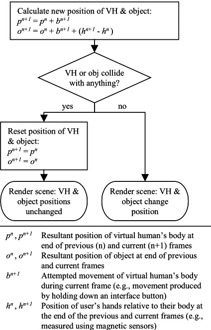
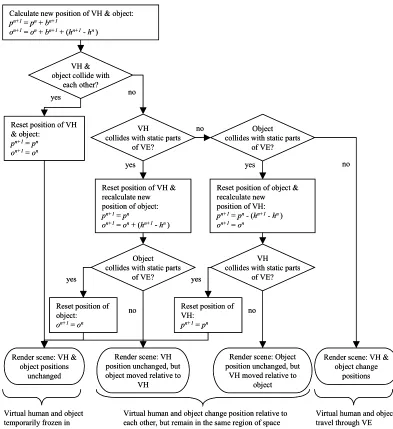
In any given graphics frame, the user attempts to move the virtual human to a new position and, by manipulating the human’s hands, maneuver the object through the VE. With stop-as-a-whole collision response there are two possible sets of resultant positions in each frame (see Figure 2). If there is no collision then the VE software allows the attempted movements to take place. Otherwise, the human and the object are reset to the (non-colliding) positions that they had at the end of the previous frame. In effect, the positions of the human and object are momentarily frozen. Stop-by-parts allows four sets of positions, depending on which entities, if any, are in collision (see Figure 3) so, under most circumstances, some movement will be allowed. The two extra sets of positions are extremely important because they allow the user to manipulate the object even if they are against a “solid” obstacle such as a wall, or make small adjustments in the human’s position, by an amount that is equal and opposite to their hand movements, even if the object is in collision. There are even greater benefits in situations where the object was being carried collaboratively by two (or more) users because each can independently adjust their position when collisions occur (see [10]).
Figure 2. Flow chart for stop-as-a-whole collision response. VH = virtual human.
3. ORDER OF CONTROL
VEs offer a choice between the precision and speed with which movements are made. Precision is greatest when zero-order (displacement) control is used and movements of an interface device produce corresponding changes of position and orientation inside a VE (stimulus-response compatibility is maintained). An alternative is first-order control, where displacements of the device, or the holding down of an interface button, change the velocity of an entity within the VE. First-order control allows large movements to be made with minimal input, but is unsuitable for the precision that is central to interaction in cluttered VEs. Positions and orientations cannot be adjusted directly and, instead, the user must make small adjustments in velocity to complete the required maneuvers. Ideally, therefore, it should be possible to achieve all forms of movement in a cluttered VE using zero-order control.
The movements that users need to make in cluttered VE can be divided into three types: (a) changes of position of their virtual body, (b) changes of their view direction, and (c) manipulations of objects they are holding, produced by movements of their virtual hands. Zero-order control is the norm for object manipulation, and can be achieved by tracking a user’s hands or using a prop-type interface such as the Polhemus 3Ball. In immersive VEs, zero-order control is also the norm for the user’s direction of view and is performed via head tracking. In desktop
VEs, however, first-order control is more common. An example is where the user’s view is rotated when they move the cursor away from the center of the display. The rate of rotation can either be constant, or increase with the distance of the cursor from the center.
Zero-order control for changes of position of a user’s virtual body is more problematic. If a large physical space and wide-range sensors are available then the user can actually walk round a VE, but the facilities required usually render this approach impractical. Another option is for the user to “walk in place” to travel through a VE and, while this approach seems promising, developments have not yet reached the stage where such an interface can be implemented commercially ([13]; personal communication J. N. Templeman, 11 January 2001). Therefore, large translationary movements are usually made using first-order (velocity) or second-order (acceleration) control, for example, by holding down a button to accelerate in the user’s direction of view. However, current sensor technology is ideally suited for implementing a hybrid interface for translationary movements in a cluttered VE.
In this hybrid interface, large changes of position are performed using first- or second-order control, but small changes of position can be performed using two variants of zero-order control. The first of these occurs when the object that a user is carrying is in collision with the VE and stop-by-parts collision response is being used. To compensate for the fact that the object cannot be moved, the user’s body is moved in an equal and opposite direction to movements of their hands, as shown in Figure 3. The second is similar but involves a mode switch in the interface that the user uses to indicate that the human’s hands should be kept stationary and the human’s body should move by an amount that is equal and opposite to the user’s physical hand movements. The only difference between these two types of control is that, in the second, the user makes an input to the interface (e.g., by holding down a button) to temporarily lock their virtual hand position, instead of relying on a collision. The three different forms of movement are easily combined. Referring back to Figure 3, the only change required is in the initial calculation of the new position of the virtual human and the object (the uppermost box in the figure). If the mode switch is invoked then these positions become:
on+1 = on + bn+1
pn+1 = pn + bn+1 - (hn+1 - hn)
4. PHYSICAL COMPATIBILITY
The purpose of physical compatibility in an interface is to help ensure that a user adopts a realistic posture when they manipulate a virtual object. It does this by making the user’s physical and virtual hand position the same as each other, relative to their body, so that interaction that would be awkward in the real world (e.g., assembling something above head height) cannot be performed in a more comfortable position in a VE (e.g., at waist level). The converse is also true, and may aid interaction by helping to prevent users from adopting unnecessarily awkward postures during interaction.
Unfortunately, physical compatibility further complicates a VE’s interface software. This section first describes the implementation of manipulation in a cluttered VE without physical compatibility, and then describes the modifications that are required to preserve it.Throughout, we are only concerned with the physical
VH or obj collide with anything?
yes no
Calculate new position of VH & object:
pn+1=pn+bn+1
on+1= on+bn+1+ (hn+1-hn)
Reset position of VH & object:
pn+1=pn
on+1= on
Render scene: VH & object positions
unchanged
Render scene: VH & object change
position
pn,pn+1 Resultant position of virtual human’s body at
end of previous (n) and current (n+1) frames
on ,on+1 Resultant position of object at end of previous
and current frames
bn+1 Attempted movement of virtual human’s body
during current frame (e.g., movement produced by holding down an interface button)
hn,hn+1 Position of user’s hands relative to their body at
the end of the previous and current frames (e.g., measured using magnetic sensors)
VH or obj collide with anything?
yes no
Calculate new position of VH & object:
pn+1=pn+bn+1
on+1= on+bn+1+ (hn+1-hn)
Reset position of VH & object:
pn+1=pn
on+1= on
Render scene: VH & object positions
unchanged
Render scene: VH & object change
position
pn,pn+1 Resultant position of virtual human’s body at
end of previous (n) and current (n+1) frames
on ,on+1 Resultant position of object at end of previous
and current frames
bn+1 Attempted movement of virtual human’s body
during current frame (e.g., movement produced by holding down an interface button)
hn,hn+1 Position of user’s hands relative to their body at
Figure 3. Flow chart for stop-by-parts collision response. b, h, o and p are as in Figure 2.
compatibility of the user’s hand position, although the concept could be extended to include posture as a whole.
The occurrence of collisions means that there are frequently occasions when a virtual human’s hand cannot be in a position that is physically compatible with that of the user, for example, the human’s hand cannot be in the middle of a virtual wall. The most straightforward way of handling this within the VE software is to implement an offset between the virtual and physical hand positions, as shown in Figure 4. During non-colliding movement, the virtual and physical hand positions change by an identical amount (the hand position offset vector, ho, remains constant). If a
collision occurs then either the position of the human’s body is moved by an amount that is equal and opposite to the movements of the user’s hands (as described above; see Figure 3) or, if collisions make that impossible, then the virtual hand and body positions remain unchanged and the offset vector is altered to
compensate. A similar offset can be implemented for the orientation of the human’s hand and a clutch [15] used to redefine both offsets without altering the position and orientation of the virtual hand. One further piece of functionality needs to be implemented, and that is to check whether the user is extending the virtual human’s reach beyond a realistic region. When that occurs, the human’s hand remains stationary and the offset is redefined. Clearly, feedback should also be provided so the user is informed of the reason for the hand being momentarily frozen in position.
If physical compatibility is to be maintained then there are a number of differences in the rules that govern interaction. First, a user’s reach does not have to be checked because it is the same as their physical reach. Second, a clutch cannot be used to redefine the relative position of the user’s virtual and physical hand because, by definition, they must be the same. The orientation
yes Calculate new position of VH & object:
pn+1=pn+bn+1
on+1= on+bn+1+ (hn+1-hn)
VH & object collide with
each other?
Object collides with static parts
of VE?
yes no
VH collides with static parts
of VE?
Reset position of VH & recalculate new position of object: pn+1=pn
on+1= on+ (hn+1-hn)
yes
yes
no Object
collides with static parts of VE?
VH collides with static parts
of VE? Reset position of object & recalculate new
position of VH: pn+1= pn- (hn+1-hn) on+1= on
yes
Render scene: VH & object positions
unchanged Reset position of VH & object:
pn+1=pn on+1= on
Reset position of VH:
pn+1= pn
Reset position of object: on+1= on
Render scene: VH position unchanged, but object moved relative to
VH
Render scene: VH & object change
positions Render scene: Object
position unchanged, but VH moved relative to
object
no
no no
Virtual human and object change position relative to each other, but remain in the same region of space because there is a collision
Virtual human and object travel through VE Virtual human and object
temporarily frozen in position
yes Calculate new position of VH & object:
pn+1=pn+bn+1
on+1= on+bn+1+ (hn+1-hn)
VH & object collide with
each other?
Object collides with static parts
of VE?
yes no
VH collides with static parts
of VE?
Reset position of VH & recalculate new position of object: pn+1=pn
on+1= on+ (hn+1-hn)
yes
yes
no Object
collides with static parts of VE?
VH collides with static parts
of VE? Reset position of object & recalculate new
position of VH: pn+1= pn- (hn+1-hn) on+1= on
yes
Render scene: VH & object positions
unchanged Reset position of VH & object:
pn+1=pn on+1= on
Reset position of VH:
pn+1= pn
Reset position of object: on+1= on
Render scene: VH position unchanged, but object moved relative to
VH
Render scene: VH & object change
positions Render scene: Object
position unchanged, but VH moved relative to
object
no
no no
Virtual human and object change position relative to each other, but remain in the same region of space because there is a collision
Virtual human and object travel through VE Virtual human and object
offset can, however, be redefined because that is the equivalent of a person changing their grasp on an object. Third, a complication occurs when there is a collision and physical compatibility cannot be maintained. Feedback can be provided to indicate where the physically compatible position would be (see Figure 5) but the object will suddenly jump in position when the user moves their hand to a new non-colliding position and this position could lie on another side of the obstacle with which the original collision took place. For example, the object could be jumped from one side of a virtual wall to another.
Figure 4. The offset between a user’s physical and virtual hand positions.
Figure 5. View inside the C-shaped VE used in the experiment. The object is being moved through the doorway
but is in collision with the wall (indicated by graphical highlighting) and the wireline image of the object indicates its
physically compatible position.
Fortunately a solution is at hand which avoids the disturbing break in visual continuity that is caused by the object jumping and prevents the object from being moved across an obstacle. The solution is to limit the rate at which the object can be moved in the immediate aftermath of a collision, using a rapid controlled movement algorithm based on that proposed by [6]. The object moves quickly, but smoothly, to the new non-colliding position, but the collision detection performed at the end of each frame prevents it from being moved through an obstacle during this automatic movement. The sequence of movements is shown in Figure 6. At all times, the object attempts to move toward its physically compatible position, and a wireline image (see Figure 5) is provided as feedback when it is not in that position.
5. EVALUATION OF FLEXIBLE
INTERACTION
Formal experiments show that object manipulation takes 30% less time in highly cluttered VEs (the C-shaped VE, see below) when stop-by-parts collision response is implemented than with stop-as-a-whole [11]. This large advantage for flexible rules of interaction arose even in an experimental situation where participants may
have been able to compensate for some of the deficiencies of stop-as-a-whole by being more precise with their actions for the duration of the experimental task, even though they could not sustain that precision over an extended period of time.
The experiment described below followed on from the one mentioned above [11]. Given that the magnitude of the performance advantage had already been demonstrated, this new experiment investigated the interaction behavior of participants when they used a single (flexible) set of rules of interaction. The rules allowed individuals to use the interface in a variety of ways, with the extent to which they used each aspect of flexibility being measured.
6. EXPERIMENT
Each participant underwent a period of training and then performed test trials in which they carried a Shepard-Metzler (SM [12]) object through two parts of a virtual building. These were two doors that were offset from each other, and a C-shaped
section of corridor. The offset VE provided an easier task than the C-shaped VE because there was more space in which to maneuver the object.
6.1 Method
6.1.1 Participants
Six participants (five men and one woman) took part in the experiment, and their ages ranged from 24 to 37 years. All the participants volunteered for the experiment and were paid an honorarium for their participation.
6.1.2 Materials
The VE software was a C++ Performer application that was designed and programmed by the authors, and ran on a SGI Maximum IMPACT workstation. The application update rate was 20Hz.
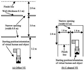
Interior views of the two environments are shown in Figures 1 and 5, and plan views in Figure 7. The offset VE contained two doorways that were offset by 1.0 m. The other VE contained a C-shaped corridor. Each VE contained a “finish line” that indicated where participants had to carry the object to. The object had a cross section of 0.5 x 0.5 m, was 1.5 m long and had a 1.0 m stub at each end (see Figures 1 and 5). These were at 90 degrees to each other.
Each participant performed the experiment while physically standing up, facing an 86 cm (34 inch) monitor that was positioned 1.60 m away on a table. A participant’s position and orientation in an environment was indicated by a 3D model of a virtual human that held the object being manipulated (see Figures 1 and 5). The participant’s viewpoint was positioned 3 m behind the position of the virtual human, allowing them to see the human’s immediate surroundings in the VE. This type of over-the-shoulder viewpoint has been used successfully in a number of previous systems (e.g., [3]), but meant that the participant’s viewpoint was sometimes on the opposite side of a wall to the human. When this occurred, the walls in question were rendered transparent. The field of view was 48 x 36 degrees.
The rules of interaction were as described in the introduction (i.e., stop-by-parts collision response, hybrid movement control, and physical compatibility). Participants controlled their movement using a cuboid prop (100 x 75 x 40 mm) that they held in their hands. The prop had a Polhemus Fastrak sensor mounted on the top and four buttons. The position and orientation of the prop was Virtual hand position, hv
Physical hand position, hp
Offset between virtual and physical hand position, ho = hv-hp
h
vh
oh
pVirtual hand position, hv
Physical hand position, hp
Offset between virtual and physical hand position, ho = hv-hp
h
vh
oh
pFigure 6. Flow chart showing the implementation of physical compatibility (PC) with controlled movement to prevent an object from jumping in the aftermath of a collision. For clarity, only position changes are shown. Changes of orientation are similar. The 30 mm criterion assumes a constant frame rate of 20 Hz. The criterion used in the experiment varied with the frame rate to give a
constant limiting speed of movement of 0.6ms-1.
Figure 7. Plan views of the offset (a) and C-shaped VEs (b). In both cases, the ceiling was at a height of 2.4 m and the narrow openings were 2.0 m high.
Calculate new PC position of object
Object collides? Position PC in
last frame?
Render scene (no feedback)
yes
Move object by 30 mm towards new PC position
Render scene: Show feedback (wireline version of object) in PC position
yes
no no no
Reset object to previous position
yes
Previous (actual) position within 30 mm
of new PC position?
Object collides? yes
Move object to new PC position
no
Narrow opening
(width 0.8 m)
Finish line
Starting position/orientation
of virtual human and object
3.0 m
2.0 m
3.2 m
Wall (thickness 0.1 m)
(a) Offset VE
Narrow opening
(width 0.8 m)
Finish
line
Starting position/orientation
of virtual human and object
2.8 m
1.8 m
1.8 m
(b) C-shaped VE
Narrow opening
(width 0.8 m)
Finish line
Starting position/orientation
of virtual human and object
3.0 m
2.0 m
3.2 m
Wall (thickness 0.1 m)
(a) Offset VE
Narrow opening
(width 0.8 m)
Finish line
Starting position/orientation
of virtual human and object
3.0 m
2.0 m
3.2 m
Wall (thickness 0.1 m)
Narrow opening
(width 0.8 m)
Finish line
Starting position/orientation
of virtual human and object
3.0 m
2.0 m
3.2 m
Wall (thickness 0.1 m)
(a) Offset VE
Narrow opening
(width 0.8 m)
Finish
line
Starting position/orientation
of virtual human and object
2.8 m
1.8 m
1.8 m
(b) C-shaped VE
Narrow opening
(width 0.8 m)
Finish
line
Starting position/orientation
of virtual human and object
2.8 m
1.8 m
1.8 m
Narrow opening
(width 0.8 m)
Finish
line
Starting position/orientation
of virtual human and object
2.8 m
1.8 m
1.8 m
[image:7.612.138.467.388.660.2]measured using the sensor and the MR Toolkit. If a participant held down one button they accelerated forwards (i.e., in their direction of view) at 0.5 ms-2, to a maximum speed of 0.5 ms-1, and if they held down another button they accelerated backwards at the same rate. The third button acted as a clutch that allowed participants to reorient the prop and, therefore, their hands without changing the orientation of the object. The fourth button was used to change the mode of the Fastrak sensor. When the button was held down, changes of the prop’s orientation caused the participant’s direction of view to be rotated (this was done because a large monitor was being used, rather than an head-mounted display). If the participant held down the third and fourth button then their virtual hand position was locked and they could reposition the human’s body relative to their hands (zero-order control). At all other times, the prop directly controlled the orientation of the object (hand-centered manipulation was used; Bowman & Hodges, 1997).
6.1.3 Procedure
All the participants had previously taken part in other experiments that investigated the use of less flexible rules of interaction (e.g., stop-as-a-whole collision response) to perform the piano movers’ problem in VEs. This meant that every participant was familiar with the experimental task and with the concept of manipulating bulky virtual objects through cluttered VEs.
In the present experiment, the experimenter started by demonstrating how to use the interface and explaining the rules of interaction. Then they demonstrated how to move the object through the offset VE. A participant then performed five trials in this VE carrying the object from the start position to the finish line. The first two of these were practice trials, and the other three were test trials. After this the experimenter demonstrated how to move the object through the C-shaped VE, and the participant performed two practice trials and three test trials. Each participant took approximately 30 mins to complete the experiment.
6.2 Results and Discussion
There was little difference between participants’ use of the interface in the three test trials with each VE so only mean data are reported. The mean time that participants took to complete the trials in the offset and C-shaped VEs was 48.8 s and 77.8 s, respectively. However, the focus of the experiment was to investigate the extent to which participants used the flexibility provided by the rules of interaction to move the object through the VEs. Therefore, participants’ interaction in each test trial was broken down into periods when they were: (a) using the clutch to re-orient their hands relative to the object, (b) repositioning their body relative to their hands while using the buttons on the prop to indicate that the object’s position should be frozen, (c) the object was in collision, or (d) there was no collision (i.e., the object was being freely manipulated or carried). If two of these occurred simultaneously, for example, a participant used the clutch while the object was in collision, then the first one took precedence. The amount of each type of interaction that took place was then expressed as a percentage of the relevant trial’s completion time. The percentage of time that participants spent performing each type of interaction is shown in Figure 8. For the majority of the time the object was not in collision. A further breakdown of this time showed that in the offset VE participants spent an average of 33% of the trial time stationary (standing in one place and either manipulating the object or deciding on a course of action) and
43% of the time moving through the VE. In the C-shaped VE these figures were 37% and 32%.
Offset C-shaped
% ti
me
0 20 40 60 80 100
[image:8.612.332.540.94.262.2]Clutch Reposition Collision Not in collision
Figure 8. Percentage of time spent performing each type of interaction in the offset and C-shaped VEs. Error bars
indicate the standard error.
For a substantial minority of each trial participants were using the flexibility provided by the interface and it is this with which we are primarily concerned. The percentage of time that participants spent using the clutch ((a) above) was similar in the two VEs. The percentage of time that participants spent repositioning their virtual body ((b) above) was also similar. In the offset VE this was mainly performed when participants sidestepped between the two doors. In the other VE participants tended to use this functionality to align themselves for negotiating the C-shaped bend.
The remainder of the time (7% and 17% of the trial time in the offset and C-shaped VEs, respectively) was when the object was in collision with the environment but the clutch was not being used and sidestepping was not being performed. The stop-by-parts collision response algorithm allowed a participant to reposition the virtual human even if the object was in collision with the fabric of the VE (the floor, walls or ceiling), thereby facilitating progress through the environment. However, the amount of time spent in collision does not indicate the extent to which the virtual human was repositioned. To determine this, collision time in each trial was divided into periods when the position of the human was either being changed by a participant moving their hands (if the object was in collision the virtual human’s hands remained stationary but their body moved in an equal and opposite direction, unless this caused the human to collide with a wall), or “stationary”. Stationary was defined as any graphics frame in which the position change of the human’s body was equivalent to a speed of movement of less than 0.05 ms -1 (this filtered out movements caused by sensor noise). In the offset VE, the virtual human was being repositioned for half of the collision time, but in the C-shaped VE repositioning took place for two-thirds of collision time.
7. CONCLUSIONS
This article described ways of implementing flexible rules of interaction for object manipulation in cluttered virtual spaces. These rules can be (and were) implemented as extensions to make existing forms of interaction suitable for cluttered VEs.
as the space becomes more cluttered. Stop-by-parts collision response, however, allows a user to progress through a VE at times when a less flexible algorithm would not. The extent to which this is useful is indicated by the 12% of trial time in which the position of the human was adjusted while a collision took place in the C-shaped VE. This type of adjustment took advantage of the zero-order movement provided by the interface and, to this, should be added the time when participants used the mode switch in the interface to reposition the human’s body without there being a collision.
Data for the usage of a clutch have been reported before in studies of object manipulation [15], and the present experiment provides additional evidence for the utility of such a feature. Physical compatibility does not, by itself, improve the ease with which users can interact in VEs, but it does play a role in providing realism to those interactions.
In conclusion, participants used the flexible features provided by the interface for approximately a quarter of each trial. The user of any computer system knows that even small hiccups in interaction cause immense frustration and a substantial increase in the time taken to accomplish tasks. This paper indicates the benefits that will accrue if flexible rules are built into future VE interfaces for almost any application that involves the manipulation of objects in tight spaces.
8. ACKNOWLEDGMENTS
This work was supported by grant GR/L95496 from the Engineering and Physical Sciences Research Council, and performed while Roy Ruddle was employed in the School of Psychology at Cardiff University.
9. REFERENCES
[1]
D.A. Bowman, and L.F. Hodges, “An evaluation of techniques for grabbing and manipulating remote objects in immersive virtual environments”, Proceedings of the 1997 Symposium on Interactive 3D Graphics, ACM, New York, 1997, pp. 35-38.[2]
D.A. Bowman, D.B. Johnson, and L.F. Hodges, “Testbed evaluation of virtual environment interaction techniques”, Presence: Teleoperators and Virtual Environments, 2001, vol. 10, pp. 75-95.[3]
J. Hindmarsh, M. Fraser, C. Heath, S. Benford, and C. Greenhalgh, “Object-focused interaction in collaborative virtual environments”, ACM Transactions on Computer-Human Interaction, 2000, vol. 7, pp. 477-509.[4]
J. Jacobson, and M. Lewis, “An experimental comparison of three methods for collision handling in virtual environments”, Proceedings of the Human Factors and Ergonomics Society 41st Annual Meeting, Human Factors Society, Santa Monica, CA, 1997, pp. 1273-1277.[5]
P. Jimenez, F. Thomas, and C. Torras, “3D collision detection: A survey”, Computer & Graphics, 2001, vol. 25, pp. 269-285.[6]
J.D. Mackinlay, S.K. Card, and G.G. Robertson, “Rapid controlled movement through a virtual 3D workspace”, Computer Graphics, 1990, vol. 24, pp. 171-176.[7]
W.A. McNeely, K.D. Puterbaugh, and J.J. Troy, “Six degree-of-freedom haptic rendering using voxel sampling”, Proceedings of the 1999 ACM Conference on Graphics (SIGGRAPH ‘99), ACM, New York, 1999, pp. 401-408.[8]
J.S. Pierce, A. Forsberg, M.J. Conway, M. J., S. Hong, R.Zeleznik, and M.R. Mine, “Image plane interaction techniques in 3D immersive environments”, Proceedings of the 1997 Symposium on Interactive 3D Graphics, ACM, New York, 1997, pp. 39-44.
[9]
I. Poupyrev, M. Billinghurst, S. Weghorst, and T. Ichikawa, “The go-go interaction technique: Non-linear mapping for direct manipulation in VR”, Proceedings of ACM User Interface Software & Technology (UIST '96). ACM, New York, 1996, pp. 79-80.[10] R.A. Ruddle, J.C. Savage, and D.M. Jones, “Symmetric and
Asymmetric Action Integration During Cooperative Object Manipulation in Virtual Environments”, ACM Transactions on Computer-Human Interaction, in press.[11] R.A. Ruddle, J.C. Savage, and D.M. Jones, “Evaluating rules
of interaction for object manipulation in cluttered virtual environments”, Presence: Teleoperators and Virtual Environments, in press.[12] R.N. Shepard, and J. Metzler, “Mental rotation of
three-dimensional objects”, Science, 1971, vol. 171, pp. 701-703.[13] J.N. Templeman, P.S. Denbrook, and L.E. Sibert, “Virtual
locomotion: Walking in place through virtual environments”, Presence: Teleoperators and Virtual Environments, 1999, vol. 8, pp. 598-617.