259
1
INTRODUCTION
Cold forming processes are widely used to produce small- and medium-sized components for automotive and aerospace applications. The advantages of cold forming over machining are low or no material waste and increased tensile strength. However, for high precision components post machining is often required after metal forming processes, which has been proved to be difficult and costly. Therefore production of high precision components by cold forming processes is one of the primary objectives in metal forming in order to minimise manufacturing cost and time.
Many factors influence component accuracy in cold forming processes, which cause systematic and random dimensional errors of components [1-3]. Among these factors the elastic-plastic behaviour and the thermal behaviour of the workpiece and tools during different forming stages including forming, unloading, ejection, and cooling are most significant. Industrial practice for achieving high precision components is to rectify the tool-form through proving trials. However, such a trial and error approach is time consuming and expensive. Attempts have been made to understand the quantitative relationships between component dimensional errors and the influencing factors such as material flow stress, tool stiffness and thermal effects [4-6]. Theoretical approaches are usually limited to simple geometries, whilst experimental methods are not practical in many cases to obtain dimensional errors during different process stages. Alternatively, FE simulation would provide quantitative information on how different material types and forming stages affect the dimensional errors of the cold-formed components. Thus a systematic approach may be developed to compensate component dimensional errors for improved forming precision of cold-formed components.
This paper presents an investigation of the influences of thermal, elastic and plastic characteristics of workpiece and tools on component dimensional errors in a cold forming process. The coupled thermal and elastic-plastic FE analysis provides the prediction of material flow, temperature distribution, stress and strain distributions as well as dimensional errors of the formed components during an entire forming cycle. Backward cup extrusion of low carbon steel and pure aluminium materials is studied. A quantitative evaluation of the dimensional errors of the formed components with a view of forming stages and properties of the workpiece is presented.
2 DIMENSIONAL ERRORS OF COMPONENTS
2.1 Influencing factors to component errors
A typical cold forming process comprises several stages including forming, punch unloading, and component ejection and cooling as shown in Figure 1. Dimensional errors of a formed component are usually defined by the deviation of the actual shapes from the nominal ones. In cold forming processes both systematic and random errors occur. Systematic errors show a particular trend due to tool deflections, frictional wear, thermal expansion and contraction, while random errors do not indicate any particular patterns from component to component. They are caused by various uncertainties, such as the variations of workpiece dimensions, material volume, composition, and fluctuations of tool-machine system set-up [1]. The most important factors, which cause the component systematic errors, include the imperfections of material properties, the elastic deflections of press system, elastic-plastic behaviour and thermal behaviour of tools and component. This research is mainly concerned with the later two factors for the backward cup extrusion of two materials.
ABSTRACT: This paper investigated the dimensional errors of cold-formed components due to
elastic-plastic behaviour and temperature variations of workpiece and the elastic deformation of tools.
A coupled thermal and mechanical Finite Element (FE) modelling procedure was developed to predict
the dimensional deviations of the formed components. During an entire cold forming cycle, the
material flow, temperature and stress distributions, tool deflections and dimensional errors of a
backward extruded cup were evaluated. This enables a quantitative understanding of dimensional
errors of the formed components with a view of forming stages and properties of the workpiece.
Key words: Simulation, finite element methods, metal forming, dimensional errors
Dimensional Error Prediction of Cold Formed Components Using Finite Element Analysis
H. Long and P. G. Maropoulos
School of Engineering, University of Durham, Durham, DH1 3LE, United Kingdom
Tel: 0044 191 3342515
Fax: 0044 191 3342377
260
2.2
Error representation
For a cup shape component produced by backward extrusion process, the radial errors, {ri}, as illustrated in Figure 1(d),
can be expressed by the following
{ri}= {riL}{riU}+{riE }{riC } (1)
where {riL}, {riU}, {riE} and {riC} are dimensional errors
of the formed component due to the elastic deformation of the tools at the forming stage, tool unloading, component ejection and thermal contraction during the cooling, respectively. Due to the non-uniform distributions of stress and temperature within the tools and workpiece at different forming stages, a non-linear relationship exists between the component dimensional errors and material flow stress, material deformation, forming load and tool stiffness, temperature distribution, and thermal properties of the tools and component.
3 FINITE ELEMENT MODELLING
The coupled thermo-mechanical elastic-plastic FE analysis is carried out for the backward cup extrusion process simulation using ABAQUS software [7]. The forming stages include positioning of the workpiece and tools, forming, punch unloading, component ejection and cooling to room temperature. During forming, the punch displacement is accomplished by prescribing node displacements at the top surface of the punch to deform the workpiece. At the end of forming, the punch unloading is modelled by removing the contact constraints at the component/punch interfaces. In the ejection, contact constraints between the component and die interfaces are removed and the component is released from the die container. The component and the tools are then allowed to cool to the room temperature by defining heat diffusion via film conditions and a cooling time.
FE models of the workpiece, punch, die and ejector are shown in Figure 2, in which half of the FE mesh is used in FE simulation with first-order axis-symmetric coupled displacement-temperature elements for the workpiece and tools. A fine mesh is generated for the workpiece to ensure enough nodes located on the inner and outer surfaces of the formed component so as to evaluate form errors on these surfaces.
Contact constraints between the workpiece and tools are modelled using a contact pair approach. A combined frictional model defined by the Coulomb coefficient of friction and the maximum shear strength is used in simulations [11]. Heat generation due to plastic deformation and friction as well as heat transfer between the workpiece and tools are also considered. The punch displacement for material plastic deformation is defined to be 10 mm and the punch velocity is 37.5 mm/s. The frictional coefficient is assumed to be 0.05. The initial temperature of the workpiece and tools is room temperature as 20 0C. The conversion factors of plastic deformation and friction energy into heat
Fig.2. FE model of the backward can extrusion
70
Unit: mm
22.4
15 40
r
ri, Loading
ri, Unloading
ri, Ejection
ri, Cooling
ri
(a) Forming (b) Punch unloading (c) Component ejection Punc
h
Di e
Workpie ce
Anvi l Eject or Shrink
ring
Support plate
Retain er
(d) errors of a formed cup
261 are assumed to be 95% and 100%, respectively. The heat
transfer coefficients during forming and cooling are defined to be 20 kW/m2C and 0.02 kW/m2C, respectively.
The stress-strain relationships of the workpiece materials are defined and elastic properties of the tool and workpiece materials are considered in the FE analysis. The dependence of the flow stress and thermal properties of the workpiece on temperature changes is taken into account in the definition of FE material models as shown in Figure 3 [8]. Two material types are considered, i.e. low carbon steel (DIN: C15) and pure aluminium (DIN: Al99.5). The tool material is tool steel (DIN: X165CrMoV12).
4 RESULTS AND DISCUSSIONS
4.1
Material deformation and temperature changes
The material flow, plastic strain and temperature distributions of the aluminium cup are shown in Figure 4, when the punch stroke is 3.4, 6.7 and 10 mm respectively. At
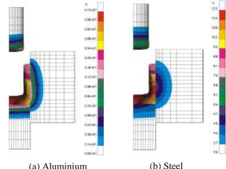
the beginning of forming, the workpiece is axially upset and a full contact between the surfaces of the punch and workpiece is developed. Further movement of the punch forces the material deformation through the gap between the punch and the die, in the opposite direction of the punch movement. The maximum equivalent strain and temperature occur on the internal wall of the can near to the bottom. Figure 5 shows the temperature distributions of aluminium and steel materials after the punch unloading. It is clear that the higher flow stress of steel results in greater temperature increase due to plastic deformation and friction heat.
4.2
Tool Elastic Deflections
[image:3.612.89.551.47.243.2]Figure 6 shows radial deflections of the die internal surface at different punch strokes. After an initial increase of die radial deflections, the maximum die deflection decreases since more material flows into the gap between the punch and die as the punch moves further and the contact area between the workpiece and the die increases. The FE modelling results obtained here are similar with experimental measurements of die deflections by other researchers [5]. (a) Pure Aluminium (DIN: Al99.5) (b) Low carbon steel (DIN: C15)
Fig.3. Material flow stresses [8]
(a) Aluminium (b) Steel
[image:3.612.339.571.535.708.2]Fig.5. Temperature distributions of aluminium and steel materials after punch removal (a) Displacement (b) Plastic strain (c) Temperature
[image:3.612.57.307.582.711.2]262 Although the die deflection profiles for extrusion of the
aluminium material shown in Figure 6(b) are very much similar t o that of the steel material in Figure 6(a), the
maximum deflection values are significantly smaller due to the lower flow stress of the aluminium material that requires a much lower force to deform the workpiece.
0 5 10 15 20 25
0 20 40 60
C
a
n
H
e
ig
h
t
(m
m
)
After Forming
0 20 40 60
After Unloading
0 20 40 60
After Ejection
0 20 40 60
After Cooling
Fig.7. Radial dimensional errors of the cup outer surface at different stages for steel material
0 5 10 15 20 25
-10 10 30
C
a
n
H
e
ig
h
t
(m
m
)
After Forming
-20 0 20
After Unloading
-20 0 20
After Ejection
-40 -20 0
After Cooling
Fig.8. Radial dimensional errors of the cup outer surface at different stages for aluminium material
0 5 10 15 20 25 30 35 40 45
0 10 20 30 40 50 60
D
ie
h
e
ig
h
t
(m
m
)
Punch stroke 2.65 mm Punch stroke 6.05 mm Punch stroke 10 mm
0 5 10 15 20 25 30 35 40 45
0 5 10 15
D
ie
h
e
ig
h
t
(m
m
)
Punch stroke 3.43 mm Punch stroke 6.68 mm Punch stroke 10 mm
Die internal surface
Radial deflection (m) Radial deflection (m)
(a) Extrusion of steel material (b) Extrusion of aluminium material
Fig.6. Radial deflections of the die internal surface during forming Formed
263
4.3
Component dimensional errors
4.3.1 Low carbon steel
Figures 7 and 8 show the radial error distributions of the cup outer surfaces at different stages for steel and aluminium materials respectively. At the end of forming, the formed cup is remain in the die container and the punch is still sustained the forming load. Hence, the errors of the cup outer surface are determined by deflections of the die internal surface, whilst the errors of the cup inner surface are affected by the punch deflections. When punch is removed, the radial stress acted on the die internal surface is reduced but still with a residual stress applied on the outer surface of the cup. The residual stress causes a compressive deflection of the cup. It has a greater influence on the outer surface than on the inner surface of cup.
After component ejection, the cup experiences an expansion resulted from the material elastic recovery deformation of the component due to its release from the die container. The lower and upper parts of the outer surfaces display an obvious radial error increase. After the cup cools to room temperature, thermal contractions occur. The final maximum radial error of the outer surface of the steel material is 36 m, appearing at the lower part of the cup.
4.3.2 Pure aluminium
Because of the much lower flow stress of aluminium, smaller maximum radial errors are obtained. After punch is removed, the maximum compressive deflections of the outer surface occur in the lower and middle parts of the cup. After the component is ejected, the maximum material elastic recovery of the outer surfaces appears in the upper part of the cup. However, due to the temperature start to decrease after
-5 0 5 10 15 20 25
0 3 6 9 12 15
Radius (mm) C a n H e ig h t (m m ) After Forming Nominal Profile -5 0 5 10 15 20 25
0 3 6 9 12 15
Radius (mm) After Unloading Nominal Profile -5 0 5 10 15 20 25
0 3 6 9 12 15
Radius (mm) After Ejection Nominal Profile -5 0 5 10 15 20 25
0 3 6 9 12 15
Radius (mm) After Cooling Nominal Profile
Fig.9. Enlarged deformation profiles of steel material at different stages (x25 radial direction)
-5 0 5 10 15 20 25
0 3 6 9 12 15
Radius (mm) C a n H e ig h t (m m ) After Forming Nominal Profile -5 0 5 10 15 20 25
0 3 6 9 12 15
Radius (mm) After Unloading Nominal Profile -5 0 5 10 15 20 25
0 3 6 9 12 15
Radius (mm) After Ejection Nominal Profile -5 0 5 10 15 20 25
0 3 6 9 12 15
Radius (mm) After Cooling Nominal Profile
264 forming, thermal contractions come into effect on
dimensional errors. As the maximum temperature occurs at the bottom corner of the cup, a greater contraction can be seen at the lower part of the outer surfaces during ejection. When the component cools to the room temperature, the outer surfaces of the cup acquire negative radial errors and the maximum error is –29 m occurred at the middle part of the cup.
The nominal profile and enlarged dimensional profiles at different stages for the steel and aluminium materials can be seen in Figures 9 and 10. It shows a significant effect of elastic-plastic and thermal behaviour of the workpiece and tools on dimensional errors. The radial errors of the outer and inner surface are varied along the axial direction. The finial dimensions of the outer and inner surfaces are larger than the nominal dimensions for the steel cup. It is suggested that the material flow stress and the elastic deflections of tools have a more prominent role than the thermal behaviour on dimensional errors for the steel material.
Comparing to the enlarged dimensional profiles of the aluminium cup with that of the steel cup, the finial radial dimensions of the aluminium component are smaller than the nominal dimensions, but that for the steel component are larger than the nominal dimensions. This illustrates the different patterns of radial errors of the steel and aluminium materials and demonstrates how material properties and forming stages affect component accuracy in backward cup extrusions. It also provides quantitative information with which different compensation approaches can be developed to further reduce the component errors for different material types.
5 CONCLUSIONS
(1) Elastic-plastic behaviour of the workpiece and tools has a significant influence on dimensional errors of the cold formed components. It affects component dimensions during forming, punch unloading and component ejection. The tool deflections after forming, material reverse deformation after unloading and component elastic recovery deformation after ejection contribute to the component dimensional errors.
(2) The material flow stress and properties of workpiece are essential to the accuracy of formed components. The elastic-plastic behaviour of the component and tools has a greater impact on dimensional errors for the steel component. Conversely, for the aluminium material, the thermal behaviour of the component has a more dominant effect on component accuracy.
6 REFERENCES
1) K. Lange et al, Hand book of metal forming.
McGraw-Hill, Inc. (1985).
2) T. Altan, S.I. Oh and H.L. Gegel, Metal forming Fundamentals and applications. American Society
for Metals (1983).
3) Kocanda, R. Cacko and P. Czyzewski, Some aspects of die deformation in net-shape cold forging, In: Proc. 5th ICTP1996, ed, T. Altan, Columbus, USA, (1996) 267-270.
4) N. Bay, Surface stress in cold forward extrusion.
Annals of the CIRP. 32 (1983) 195-199.
5) Y. Murata and Y. Yabuki, Measurement of die deformation in forging by capacitive displacement transducer. In: Proc. 4th ICTP1993, editor, Z.R. Wang, Beijing, China, (1993) 1216-1221.
6) K. Imai, Effects of tool deformation and product’ elastic recovery on the dimensional accuracy of backward-extruded cups. Journal of JSTP. 23 (1982) 35-43.
7) ABAQUS User’a Manual, v 6.1. Hibbitt, Karlsson & Sorensen Inc. (2000).