International Journal of Innovative Technology and Exploring Engineering (IJITEE) ISSN: 2278-3075, Volume-9 Issue-1, November 2019
Abstract: Multiple-input multiple-output (MIMO) radar is used extensively due to its application of simultaneous transmission and reception of multiple signals through multiple antennas or channels. MIMO radar receives enormous attention in communication technologies due to its better target detection, higher resolution and improved accurate target parameter estimation. The MIMO radar has several antennas for transmitting the information and also the reflected signals from the target is received by the multiple antennas and it mainly used in military and civilian fields. But sometimes the performance of the MIMO radars is degraded due to its limited power. So the optimum power allocation is required in the communication systems of MIMO radar to improve its performance. In this paper, an Energy Efficiency based Power Allocation (EEPA) is used to allocate the power to a user of the clusters and also across the clusters. Here, the MIMO radars are clustered by using a naive bayes classifier. Subsequently, an efficient target detection is achieved by using Generalized Likelihood Ratio Test (GLRT) and then the clusters are divided into primary and distributive clusters based on the distance from the target. Here, the proposed methodology is named as EEPA-GLRT and the implementation of this MIMO radar system with an effective power allocation is done by Labview. The performance of the EEPA-GLRT methodology is analyzed in terms of the power consumption of various clusters. The performance of the EEPA-GLRT methodology is compared with Generalized Nash Game (GNG) method and it shows the power consumption of EEPA-GLRT is 0.0549 for cluster 1 of scenario 1, which is less when compared to the GNG method.
Index Terms: Multiple-input multiple-output radar, generalized likelihood ratio test, Naive Bayes classifier, power allocation and power consumption.
I. INTRODUCTION
MIMO radar systems are an emerging and rapidly growing research area because of its target detection capability. The antennas of MIMO radar simultaneously transmit numerous independent waveforms when compared to the conventional phased-array radar. Same like it uses the multiple antennas for receiving the backscattered signals [1], [2]. The waveforms emitted by the MIMO radar vary based on the power and bandwidth [3]. The difference from the transmitted signals of the MIMO radar creates the waveform diversity or spatial diversity, it leads maximizes the Degrees Of Freedom (DOF) and this improves the MIMO radar system performance. Besides the waveform diversity provides various advantages to the MIMO radar than the conventional phased-array radar systems. This phased-array radar only sends the scaled forms
Revised Manuscript Received on November 05, 2019.
T Harikala, Electronics and communication, S.V. University, Tirupati Name, India.
R.V.S. Satyanarayana, Electronics and communication, S.V. University, Tirupati, India.
of a single waveform and cannot achieve the waveform diversity [4], [5], [6]. Additionally, this waveform diversity also emphasizes the illumination cooperation [7]. Generally, the MIMO radar system is classified into two types such as statistical MIMO radar and coherent MIMO radar. In that statistical MIMO radar is initialized with widely separated antennas and coherent MIMO radar is initialized with co-located antennas [8], [9].
Moreover, the spatial diversity of the Radar Cross Section (RCS) of target is used to improve the capability of localization and target detection. The localization accuracy depends on various parameters such as target RCS, transmit power, network topology and signal bandwidth [10]. The limited power of the radar leads to degrade the performance of the MIMO radar system. So, the power allocation strategy is introduced in MIMO radar to overcome the limitations due to radar’s power level [11]. Conventionally, the power is allocated to transmit antennas based on the addition of the power constraint at the transmitter [12]. Some of the methods used for the power allocation in MIMO radar system is given as follows: The cooperative game theory based power allocation is presented based on the target localization game with a sequential Bayesian estimator [13]. In MIMO radar, two different power allocation schemes are used. In that one is used for reducing the entire transmit power and other one increases the accuracy [14]. The robust chance constrained power allocation is used in MIMO radar by considering the probabilistic uncertainty on the target RCS [15]. The major contributions of this research work are stated as follows:
The MIMO radars of the network are clustered by using the Naive Bayes classifier for accomplishing better data transmission.
The target detection of the MIMO radar system is performed by using the generalized likelihood ratio test. The classification among the primary and distributive clusters is identified by considering the distance between the clusters and the target.
Additionally, the power allocation of intra and inter clusters is performed by considering the energy efficiency of the system. By considering the energy efficiency in the power allocation, the total power allocation of the system is reduced.
II. LITERATUREWORKS
Abtahi, A., Modarres-Hashemi, M., Marvasti, F. and Tabataba, F.S. [16] introduced the compressive sensing based distributed MIMO radars
with two different methods
for improving the
Adaptive Energy Efficiency Based Power
Allocation for MIMO Radar Network
performance of the radar network. In that, the first technique is utilized for assigning the optimal energy to the transmitters and subsequently the other technique is used for designing the optimal measurement matrix. The aforementioned two techniques depend on reducing the upper bound of the addition of the sensing matrix block’s block-coherences. These techniques lead to improve the accuracy of the estimation of target parameter in the distributed MIMO radar during the total transmitted energy is fixed as constant. The normalized processing time of the measurement matrix design is higher than the energy allocation method.
Song, X., Zheng, N. and Bai, T [17] introduced a distributed MIMO radar system with antenna selection schemes for improving the performance of resource allocation. These antenna selection schemes are introduced for tracking the multiple targets with various location estimation MSE and priorities of the targets. In this MIMO radar, the targets are moving through the test area with low attitude. Besides, the targets of the MIMO radar is not treated equally, it is separated as hot targets, suspicious targets and general targets. Here, two different operational schemes such as modified fair multistart local search with one antenna to all targets (MFMLS_OAT) algorithm and multistart local search (MFMLS) algorithm are used for a low and high location MSE respectively. The complexity of the initial antenna subset is added to the MFMLS algorithm to offer the balanced antenna allocation.
Deligiannis, A., Panoui, A., Lambotharan, S. and Chambers, J.A [18] presented the power allocation in the multistatic and distributed radar network. In that network, the MIMO radars are divided into multiple clusters. In this MIMO radars, the power allocation is performed by game theory and Nash equilibrium analysis is used for the multistatic MIMO radar system. The concern due to power adaptation is avoided by using convex optimization methods and non-cooperative game-theoretic techniques. The aforesaid techniques are incorporated using the signal-to-interference-plus-noise ratio (SINR). The Generalized Nash Game (GNG) is formulated when there is no communication among the clusters. Hence, the performance of the radars present in the clusters is specified by the game-theoretic analysis. Here, only one radar is transmitting in the zero probability even when the
n
amount of radars have the SINR equality.Wang, L., Wang, L., Zeng, Y. and Wang, M [19] introduced the jamming power allocation strategies based on two different criteria such as Minimum Mean Square Error (MMSE) and Mutual Information (MI) among the target impulse response and radar echo. In this, the jamming methods of MMSE and MI are used for increasing the MMSE target estimation and reducing the MI among the MIMO radar’s target impulse response and echo. The jamming power allocation is possible only when the system knows the noise Power Spectral Density (PSD), radar waveform power allocation, and target PSD.
Song, X., Zheng, N., Yan, S. and Li, H [20] presented the joint resource allocation method to enhance the resource utilization and system performance of the distributed MIMO radar systems. This joint resource allocation method
addresses the velocity estimation problem while processing the multiple targets tracking in MIMO radar. This power allocation method leads to enhance the key target performance while increasing the resource utilization of the general targets. The suboptimal method is initialized to solve the issues related to the limited and relatively sufficient system resources. Then the convex relaxation is used to convert the optimization problem into a three-step suboptimal method and here each step performs the Second-Order Cone Programming (SOCP) problem. The proposed algorithm is applicable only to limited users.
[image:2.595.330.509.207.663.2]III. EEPA-GLRT METHODOLOGY
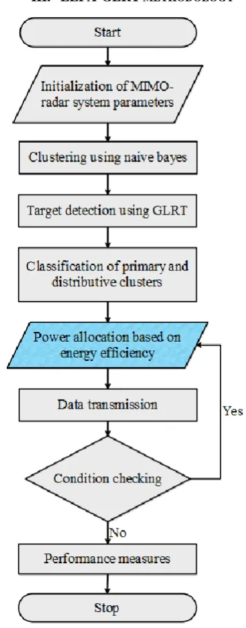
Figure 1. Flowchart of the EEPA-GLRT methodology In this EEPA-GLRT methodology, an efficient power allocation between the users of clusters and across the clusters are used to allocate enough power to the radar systems for maintaining proper data transmission through the MIMO-radar system. The flowchart of the EEPA-GLRT methodology is shown in
International Journal of Innovative Technology and Exploring Engineering (IJITEE) ISSN: 2278-3075, Volume-9 Issue-1, November 2019
steps. 1) MIMO-radar deployment in the test area, 2) Clustering of radars using naive bayes, 3) GLRT based target detection, 4) classification of primary and distributive clusters, 5) Energy efficiency based power allocation, 6) Data transmission.
A. MIMO radar system model
Generally the MIMO radar network is initialized withM number of transmitter antennas and Namount of receiver antennas with target. In this MIMO radar network, the target is considered as a point among each pair of transmitting and receiving antennas. The nth antenna received signal component at the th
k time is given in Eq. (1).
1
, 1,...., K
M
n in i n
i
y k h s k k k
(1)Where, the transmitted signal of ith antenna is represented as s ki
; the impulse response among the transmitter antennai and the receiver antenna n is hinand the noise in the
receive antennanis
k . The noise vector components are considered as independent and equally distributed Gaussian random variables with variance and zero mean. The vector form of signal model is expressed in Eq. (2).
T
n n n
y k h s k
k (2) Where, hn
h1n,h2n,...hMn
T and
1
, 2 ,...,
T M
s k s k s k s k . The K amount of samples are stacked to obtain the received signal in the th
n
receive element. These signals are received in T seconds of observation time which is expressed in Eq. (3).
T T n n n n
y h S (3) WhereS s
1 ,s 2 ,...,s K
T. The matrix form of the received signals is created by gathering the received waveforms from all N amount of receive elements. The following Eq. (4) shows the received waveform of MIMO radar system.YSH (4) Where, Y y1T,y2T,...yTN . This received signal is
Gaussian distributed with the covariance of SR SH H
2Ikand zero mean. These MIMO radars are clustered by using Naive bayes classifier.
B. Target detection using GLRT
In this EEPA-GLRT methodology, the presence of target is detected by using a binary hypothesis testing at the received signal. This target detection is depending on the Generalized Likelihood Ratio Test (GLRT). The detection probability
, ,
D i i i
p
and false alarm pFA i,
i is expressed in the following Eq. (5).
, 1 , 1 1 . 1 1 1 I ND i i i
i i
N FA i i i p N p (5)
Where, the decision threshold is represented as i ; the amount of received pulses at time on target isNand the SINR collected at the radar iis i which is given in Eq. (6).
, 2 , , , 1, 1 T t i i i i Md t
i j i j j i j j w j j
h P
c h P h P
(6)The numerator of Eq. (6) describes the return signal which is scattered off the target as well as the denominator has noise and interference. The above Eq. (6) is rewritten as Eq. (7).
,
t i i i i i h P I
(7) Where, Ii represents the total interference and noise
collected on the radari which is expressed in the following Eq. (8).
2, , ,
1,
T
M
d t
i i j i j j i j j w i j i
I c h P h P
(8) For certifying the performance of target detection, the ithradar received SINR is less than the predefined minimum value i.e. min . The condition for the target detection is given in Eq. (9).
min
i
(9) Then the clusters are classified as primary and distributive clusters based on the distance among the target and the clusters.
C. Power allocation based on the energy efficiency The energy efficiency based power allocation is used in this EEPA-GLRT methodology, to allocate the efficient power to the users/clusters which doesn’t have enough energy for performing the data transmission. The power allocation should be introduced in the MIMO radar system to avoid data loss through the system. Generally, the power consumption of the MIMO radar system is separated as two types such as fixed circuit power consumption
Pc and flexible transmitpower
Pt . The following Eq. (10) represents the flexible transmit power.max .
1 1
M L
t m l
m l
P P
(10) Where, Pmaxis the total transmit power to the BS andm l. is the power allocation coefficient.The Energy Efficiency (EE) of the system is expressed in the following Eq. (11).
sum EE c t R P P
(11)
Where, the achievable sum rate is represented as Rsum i.e.,
, 1 1 M L sum m l m l R R
. The objective of this EEPA-GLRT(12a)
min
, ,
. . m l m l, 1,... , 1,....
s t R R m M l L (12b)
, 1 1
1
M L m l m l
(12c) Where, the minimum rate requirements of user and transmit power constraint is represented in Eq. (12b) and (12c) respectively.The objective function mentioned in Eq. (12) is in fractional form. Hence (12) is a non-convex problem and obtain an optimal solution that is non-trivial. Based on Eq. (11), the SE is maximized for increasing the EE under the
condition ofP Pf, f Preq,Pmax . The following Eq. (13)
formulates the maximization problem of SE.
,
max sum
m l
R
(13a)
min
, ,
. . m l m l, 1,... , 1,....
s t R R m M l L (13b)
max ,
1 1
M L
m l f m l
P P
(13c) The formulated a problem of Eq. (13) is still non-convex because of the non-concavity which is involved in the objective function. To provide the optimal solution to the MIMO-radar system, the power allocation is used within each cluster and across clusters. The power allocation of each cluster and across clusters are described as follows:1) Power allocation of each cluster
In the power allocation of inside cluster, each user receives enough power to satisfy the Quality of Service (QoS) requirements of the EEPA-GLRT methodology. Here, enough power is allocated to every user to increase the cluster sum rate. Consider, the power transfer happens among the th
n
user and first user by using the EEPA. After performing the power transfer, the achieved sum rate of the user with a worse channel increases than the th
n user that is remain unchanged. The first n users are compared, when comparing the sum rates of two cluster. The following Eqs. (14) and (15) show the sum rate of before and after performing the power transfer respectively.
2 ,k , , 1
1 2
, ,l 1 , 1
, 2
1
1 1
2 , , ,l 1 1 1 log 1 l H m m l m l m k
n n
n
H
m k m m l m m l
k
l l
n
H m k m n m m k
v H p
v H p
R
v H p
(14) 2 , , , 1 1 2 ', , 1 ,
, 2
1
1 1
2 , , ,n 1 1 1 log 1 l H tr m k m l m l m
k l n
n
H
tr m k m l m l m m l
k
l l
n
H m k m n m m k
P v H p
P v H p
R
v H p
(15)From the Eq. (14) and (15) concluded that the
2 2
, , , 1 , 1
H H
m l m l m m l m l m
v H p v H p . So, therefore
'
, ,
1 1
n n
m l m l
l l
R R
it shows the sum rate of the MIMO radar system is increased after performing the power allocation. The power allocation to the desired user increase the sum rate of the entire system.2) Power allocation of across the clusters
At first, the power is allocated within the clusters for satisfying the QoS requirements that requires power of Preq . the remaining power is denoted as PremPf Preq . The overall system rate is maximized by allocating the remaining power across the clusters. The amount of additional power required for desired cluster is identified while increasing the sum rate. The power required for th
m cluster by R is expressed in the following Eq. (16).
max ,1 2 , , 2 2 1 m l L R l m H m l m l m
P R
P
v H p
(16)The power increment for each cluster is affected by the user’s channel gain and minimum rate requirement. The less additional power is required to increase the sum rate for
smaller , max 1 2 , ,
2 m l
L
l H m l m l m
P R
v H p
. This observation is utilized for
designing the iterative power allocation algorithm. In an each
iteration, the cluster with lesser
min max , 1 2 , , 2 L m l l H
m l m l m
P R
v H p
is chosen to
receive the extra power. Thus leads to increase its sum rate and this process is continued until the full utilization of Pf . The extra power required for the cluster is expressed in the Eq. (17). min max , 1 2 , , 2 L m l l m H m l m l m
P R
P
v H p
(17)Where,
represents the auxiliary variable and it is expressed in following Eq. (18).min max , 1 2 , , 2 L
m l m l
H m l m l m
P R R
v H p
(18)Additionally, the required power for the mth cluster is expressed in the following Eq. (19).
min max , 1 22 , , 2 L m l l m H m l m l m
P R
P
v H p
(19)International Journal of Innovative Technology and Exploring Engineering (IJITEE) ISSN: 2278-3075, Volume-9 Issue-1, November 2019
IV. RESULTSANDDISCUSSION
In this section, simulation results are provided to demonstrate the performance of the EEPA-GLRT
methodology. The EEPA-GLRT methodology is
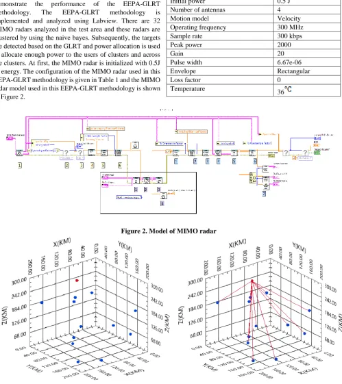
implemented and analyzed using Labview. There are 32 MIMO radars analyzed in the test area and these radars are clustered by using the naive bayes. Subsequently, the targets are detected based on the GLRT and power allocation is used to allocate enough power to the users of clusters and across the clusters. At first, the MIMO radar is initialized with 0.5J of energy. The configuration of the MIMO radar used in this EEPA-GLRT methodology is given in Table 1 and the MIMO radar model used in this EEPA-GLRT methodology is shown in Figure 2.
Table.1. MIMO radar specifications
Parameters Values
Initial power 0.5 J
Number of antennas 4
Motion model Velocity
Operating frequency 300 MHz
Sample rate 300 kbps
Peak power 2000
Gain 20
Pulse width 6.67e-06
Envelope Rectangular
Loss factor 0
[image:5.595.56.556.81.643.2]Temperature 36
Figure 2. Model of MIMO radar
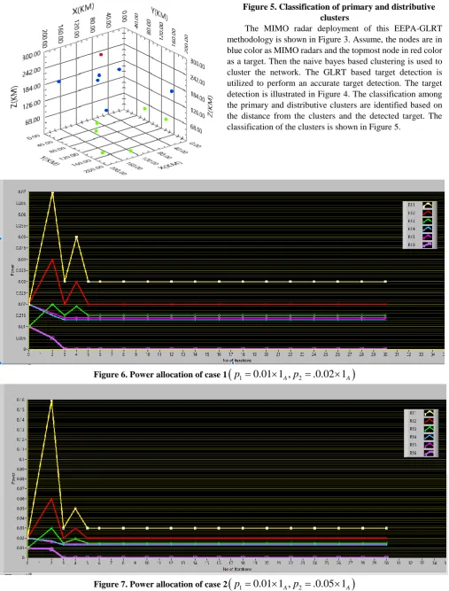
Figure 5. Classification of primary and distributive clusters
The MIMO radar deployment of this EEPA-GLRT methodology is shown in Figure 3. Assume, the nodes are in blue color as MIMO radars and the topmost node in red color as a target. Then the naive bayes based clustering is used to cluster the network. The GLRT based target detection is utilized to perform an accurate target detection. The target detection is illustrated in Figure 4. The classification among the primary and distributive clusters are identified based on the distance from the clusters and the detected target. The classification of the clusters is shown in Figure 5.
Figure 6. Power allocation of case 1
p
1
0.01 1 ,
Ap
2
.0.02 1
A
Figure 7. Power allocation of case 2
p
1
0.01 1 ,
Ap
2
.0.05 1
A
The power allocation update of MIMO radars of the network is shown in Figure 6 and Figure 7. The Figure 6 and Figure 7 shows the power allocation performance for two different initial power allocations (i.e., case 1 and case 2) of
the clusters. These simulations are taken for the network with 2 clusters and each cluster
has 6 radars. Moreover the
International Journal of Innovative Technology and Exploring Engineering (IJITEE) ISSN: 2278-3075, Volume-9 Issue-1, November 2019
Figure 6 and Figure 7 represents the radars exist in the cluster and
A
represents the amount of radars in cluster. From the Figure 6 and Figure 7, conclude that the channel gain is remain similar for both the simulations. The amount of active radars for both the clusters is same for both the simulations but the initial power allocation is different for both examples. Here, the power allocation is mainly depending on the energy efficiency of the network. From the Figures, it concludes that the optimal power allocation is converged within 5 iterations.A. Performance comparison of EEPA-GLRT methodology with existing method
This section used to analyze the effectiveness of the EEPA-GLRT methodology with one existing method called
GNG [18]. This GNG is used to perform the communication among the clusters and performance of this GNG is analyzed based on the game theoretic analysis. The comparison is made in terms of power consumption of the clusters and it is shown in the following Table 2. This comparison is evaluated in three different scenarios that are mentioned as below:
Scenario 1: The network consisting of 2 clusters each with 2 MIMO radars.
Scenario 2: The network consisting of 2 clusters each with 6 MIMO radars.
Scenario 3: The network consisting of 3 clusters each with 3 MIMO radars.
Table 2. Performance comparison of EEPA-GLRT methodology with existing method
Scenario 1 Scenario 2 Scenario 3
C1 C2 C1 C2 C1 C2 C3
GNG [18] 0.0763 0.0418 0.1382 0.1398 0.0641 0.1190 0.0895
EEPA-GLRT methodology 0.0549 0.0217 0.0943 0.0974 0.0289 0.0197 0.0141
The
C C and C
1, 2
3
mentioned in the Table 2 specifiesthe clusters of the network. Table 2 conclude that the power consumption of the EEPA-GLRT methodology is less than the GNG [18] method. Because, the EEPA-GLRT methodology provides an effective power allocation based on the energy efficiency. For instance, in scenario 1, the EEPA-GLRT methodology power consumption are 0.0549 and 0.0217 for cluster 1 and cluster 2 respectively, it is less when compared to the GNG that are 0.0763 and 0.0418 of cluster 1 and cluster 2 respectively. Also, this EEPA-GLRT methodology allocates the power to the members in the clusters as well as across the clusters. Moreover, the convergence of optimal power allocation of EEPA-GLRT methodology took 5 iterations, it is less than the GNG [18] i.e., 6 iterations.
V. CONCLUSION
The energy efficiency based power allocation is introduced in the EEPA-GLRT methodology to allocate the power for both inter and intra clusters. In energy efficiency based power allocation, the user (i.e., MIMO radar) with less energy receives the power from the other users of same cluster. Thus leads to improve QoS requirements of the EEPA-GLRT methodology namely power consumption. This power allocation strategy is implemented over naive bayes based clustered radars. The MIMO radars are separated as clusters to improve the data transmission performance of the EEPA-GLRT methodology. Moreover, the target detection is obtained precisely by using the GLRT method. The research concludes that the EEPA-GLRT methodology converges the optimal power allocation within 5 iterations, it is less when compared to the GNG method i.e., 6 iterations. Furthermore, the genetic algorithm based heuristic method can be used for an efficient power allocation to reduce the overall energy consumption of the MIMO-Radar system.
REFERENCES
1. Y. Yu, S. Sun, R.N. Madan, and A. Petropulu, “Power allocation and waveform design for the compressive sensing based MIMO radar,” IEEE Transactions on Aerospace and Electronic Systems, Vol.50, No.2, pp.898-909, 2014.
2. W. Xia, Z. He, and Y. Liao, “On the maximum likelihood method for target localization using MIMO radar,”. Science China Information Sciences, Vol.53, No.10, pp.2127-2137, 2010.
3. N. Garcia, A.M. Haimovich, M. Coulon, and M. Lops, “Resource allocation in MIMO radar with multiple targets for non-coherent localization,” IEEE Transactions on Signal Processing, Vol.62, No.10, pp.2656-2666, 2014.
4. X. Lan, W. Li, X. Wang, J. Yan, and M. Jiang, “MIMO radar and target Stackelberg game in the presence of clutter,” IEEE Sensors Journal, Vol.15, No.12, pp.6912-6920, 2015.
5. Y.X. Wang, G.C. Huang, W. Li, and J.L. Li, “Colocated MIMO radar waveform-design based on two-step optimizations in spatial and spectral domains,” Frontiers of Information Technology & Electronic Engineering, Vol.18, No.7, pp.1021-1032, 2017.
6. A. Khawar, A. Abdelhadi, and T.C. Clancy, “QPSK waveform for MIMO radar with spectrum sharing constraints,” Physical Communication, Vol.17, pp.37-57, 2015.
7. X. Song, P. Willett, S. Zhou, and P.B. Luh, “The MIMO radar and jammer games,” IEEE Transactions on Signal Processing, Vol.60, No.2, pp.687-699, 2011.
8. X. Wang, Y. Xiong, B. Tang, and Y. Li, “An approach to the modulation recognition of MIMO radar signals,” In Communications, Signal Processing, and Systems, New York, pp. 343-351, 2012.
9. S. Liu, G. Zhang, J.D. Zhang, M. Yang, and Y. Tao, “Transmit and Receive Gain Optimization for Distributed MIMO Radar,” Wireless Personal Communications, Vol.85, No.4, pp.1969-1986, 2015. 10. B. Ma, H. Chen, B. Sun, and H. Xiao, “A joint scheme of antenna
selection and power allocation for localization in MIMO radar sensor networks,” IEEE communications letters, Vol.18, No.12, pp.2225-2228, 2014.
11. Y. Yuan, W. Yi, T. Kirubarajan, and L. Kong, “Scaled accuracy based power allocation for multi-target tracking with colocated MIMO radars,” Signal Processing, Vol.158, pp.227-240, 2019.
12. M. Arulraj, and T.S. Jeyaraman, “MIMO radar waveform design with peak and sum power constraints,” EURASIP Journal on Advances in Signal Processing, Vol.2013, No.1, p.127, 2013.
13. H. Chen, S. Ta, and B. Sun, “Cooperative game approach to power allocation for target tracking in distributed MIMO radar sensor networks,” IEEE Sensors Journal, Vol.15, No.10, pp.5423-5432, 2015. 14. H. Godrich, A.P. Petropulu,
multiple-radar architectures,” IEEE Transactions on Signal Processing, Vol.59, No.7, pp.3226-3240, 2011.
15. J. Yan, W. Pu, H. Liu, B. Jiu, and Z. Bao, “Robust chance constrained power allocation scheme for multiple target localization in colocated MIMO radar system,” IEEE Transactions on Signal Processing, Vol.66, No.15, pp.3946-3957, 2018.
16. A. Abtahi, M. Modarres-Hashemi, F. Marvasti, and F. Tabataba, “Power allocation and measurement matrix design for block CS-based distributed MIMO radars,” Aerospace Science and technology, Vol.53, pp.128-135, 2016.
17. X. Song, N. Zheng, and T. Bai, “Resource allocation schemes for multiple targets tracking in distributed MIMO radar systems,” International Journal of Antennas and Propagation, 2017.
18. A. Deligiannis, A. Panoui, S. Lambotharan, and J.A. Chambers, “Game-theoretic power allocation and the Nash equilibrium analysis for a multistatic MIMO radar network,” IEEE Transactions on Signal Processing, Vol.65, No.24, pp.6397-6408, 2017.
19. L. Wang, L. Wang, Y. Zeng, and M. Wang, “Jamming power allocation strategy for MIMO radar based on MMSE and mutual information,” IET Radar, Sonar & Navigation, Vol.11, No.7, pp.1081-1089, 2017. 20. X. Song, N. Zheng, S. Yan, and H. Li, “A joint resource allocation
method for multiple targets tracking in distributed MIMO radar systems,” EURASIP Journal on Advances in Signal Processing, Vol. 2018, No.1, p.65, 2018.
AUTHORSPROFILE
Harikala, Research scholar, ECE dept. in SV university, Tirupati. Presently doing research work in MIMO. Received M.Tech degree from S.V.University college of Engineering(SVUCE) , Tirupathi.