International Journal of Innovative Technology and Exploring Engineering (IJITEE) ISSN: 2278-3075, Volume-9 Issue-2, December 2019
Abstract— The target of the registration process is to get the disagreement between two captured images for the same area to candidate the transformation matrix that is used to map the points in one image to its congruent in the other image for the same area. A dynamic method is demonstrated in this paper to improve registration process of SAR images. At first, smoothing filtering is used for noise reduction based on gaussian-kernel filter to set aside the pursue-up amplification of noise. Then; area based matching method, cross correlation, is used to perform a coarse registration. The output of the coarse registration is directly applied to the regular step gradient descent (RSGD) optimizer as a fine registration process. The performance of the demonstrated method was evaluated via comparison with the common used corner detectors (Harris, Minimum Eigenvalues, and FAST). Mean square error (MSE) and peak signal-to-noise ratio (PSNR) are the main factors for the comparison. The results show that the demonstrated approach preserves the robustness of the registration process and minimizes the image noise.
Index Terms— Image fusion, image matching, image retrieval, image processing, Object detection, stereo image processing.
I. INTRODUCTION
The goal of the registration process is to catch the geometric transformation matrix between the reference image and the slave image. There are two main categories for the image registration, one of them is the area based methods and the other is the feature based methods. Image registration algorithm suitable for remote sensing has to meet several criteria : Accurate, Reliable, It should be able to handle all the occurring displacements and gray-level variations between the images to be registered, The registration should be as fast as possible and ideally fully automatic [1-5]. The combination between the approaches based on using the area based method to remove the pixel shift between the images and to use the feature based method to remove the sub-pixel shift. The coarse co-registration step is the removal of the offset in pixel level between the two SAR images. These two images must be taken under the same flight conditions for the same location. One of the two images is called the master image which is located closer to the target of interest, while
Revised Manuscript Received on December 05, 2019. * Correspondence Author
Mohammed Safy, Electrical department, Egyptian Academy for Engineering & Advanced Technology Affiliated to Ministry of Military Production, Cairo, Egypt. Email: [email protected]
Abdelhameed S. Eltanany, Radar department, Military Technical college, Cairo, Egypt. Email: [email protected]
A. S. Amein, Radar department, Military Technical college, Cairo, Egypt. Email: [email protected]
the other is called the slave image. To calculate the offset in the coarse co-registration step, there are three methods: (1) Using the cross-correlation function to estimate the offset between the two images. (2) Use the orbital data and the baseline information in the head file to estimate the offset between the two images (3) manually selection of the Features in each image. After coarse co-registration, there is a sub-pixel offset between the master image and the shifted slave image .The removing of the sub-pixel offset between the master image and the shifted slave image is called the fine co-registration [4, 6-9].
Feature based methods are based on the extraction of the same features on the two images to be aligned. These features must be stay in a fixed position through the operation, detectable and spread in all over the two images and distinct. The extracted features may be Points (region corners, line intersections, points on curves with high curvature), Lines (region boundaries, coastlines, roads, rivers), Regions (forests, lakes, fields). Manually selection of ground control points is the traditional method. But this method needs persons with high experience which lead to time consuming and a lot of laboratory work. In last 10 years many of automatic co-registration methods are developed [4, 7, 8]. Generally, the feature detectors can be categorized according to: principle of operation (template-based, contour-based, and direct-based), operating scale (single, multi, and affine invariant) [4, 8, 10]. Feature matching is the step which establishes the correspondences between the detected features in the master image and those in the slave image. Various feature descriptors and similarity measures along with spatial relationships among the features are used for that purpose. The essential step after matching the ground control points in the two images is how to map the points in the slave image to its correspondence in the master image. There are five models for this process affine, rigid, projective, polynomial and simple translation. The main different between these models is how to estimate the parameters of the transformation model. The transformation matrix should achieve the desired similarity metric to detect the specific value of nearness or the grade of convenience between the input images [4, 8, 11-14].
This issue can be treated as an optimization method to investigate the optimal parameters of the transformation model that optimize the similarity metric function [15, 16]. Gradient descent is a common technique, is utilized as black-box, to achieve the process of optimization [17]. Image registration requires
finding the transformation that increases mutual information
SAR Images Co-registration Based on Gradient
Descent Optimization
between the input images by optimizing the fitting parameters between images. Since estimating of the cost function is expensive, so the traditional descent approaches depending on approximations of gradient's finite difference are quite inactive. The reason for this is that for each refinement, accurate estimation for the cost function is required [15-18]. The registration process based on the optimization method requests a pre-defined measurement for congruency (similarity) such that the primary values of the transformation matrix parameters can be found. To develop the algorithm, update the parameters, until reaching maximum congruency value are obtained [15, 19, 20]. For all the image registration techniques it is not possible to use only one optimization technique as a norm one [21-23]. For intensities images, not all optimization techniques can be applied [15, 24, 25]. There are several algorithms of optimization can be applied, but the commonly algorithms are regularized step-size gradient descent, quasi-Newton, Powell-Brent, adaptive stochastic gradient descent, downhill simplex, standard gradient descent, evolutionary strategies, and simulated annealing [15, 26, 27]. Finally; the algorithms of optimization can be classified into: 1) Continuous as conjugate gradient descent (CGD), stochastic gradient descent (SGD), Quasi-Newton, and gradient descent (GD); 2) Discrete ones that are based on the theories of linear programming and graph; and 3) Evolutionary methods. Estimating the parameters describing the transformation can be carried out directly iteratively [15-28].
The remainder of this paper is organized as follows. Section (2) describes the Gradient Descent Optimization method. Section (3) presents the methodology of the proposed method where the frame work is described in subsection (3.1) and experimental Dataset, Results, and Analysis are presented in Section (3.2). Conclusion is given in Section (4).
II. GRADIENTDESCENT(GD)OPTIMIZATION METHOD
In general; Gradient descent is a manner to diminish the cost function characterized by a certain model's parameters. This can be achieved by renewing of parameters in the reversed side of the cost function's gradient related to these parameters [15,16, 29]. Gradient descent approach is a way to locate the local minimum of a certain function starting with a primary assumption for resolution and estimating the function's gradient at this point. Step the resolution toward the negative direction of the gradient and repeat this process till the convergence is occurred where the value of the gradient is zero, w.r.t to the required local minimum [15, 17, 23, 29]. This process is crucial for local minimum estimation. On the contrary; the target of the gradient ascent is to find the local maximum. The step size to reach the target (local minimal or maximal), is based on the rate of learning. The wrong selection of the step size will affect on the convergence and the divergence process [15, 29]. To reach the convergence take into consideration the inversely relation between the step size selection and the consumed time. This issue could be recovered using fixed or adaptive step size. Normally the gradient descent start with fixed step
size with fixed rate then several step sizes at each restoration is chosen in adaptive manner to reach the convergence [15-17, 23, 29].
The steepest descent is one of the most famous search descent methods, it is proposed for unconstrained minimization problem [15, 29]. The goals of registration process based on optimization algorithm are: 1) estimation of measurements of dissimilarity or similarity, 2) dedicating the primary parameters that used approximately for registration images as initial step, and 3) updating the parameters till developing the used algorithm taking the last form which is the best. The registration process between images is optimal when maximizing the measurement of similarity or minimizing the dissimilarity measurement. The selection of adequate similarity measurement, or dissimilarity, is based on the characteristics of the selected images to be registered [15-17, 29].
Primary parameters of the transformation matrix may be described manually or in automated manner. For manually procedures, the servant revokes one of the images over the other to be aligned, while the automated manner does not request the servant intrusion. The transformation matrix parameter of the registered images is affected by the sensor type. If the two images from the same sensors then a large step will be considered on the other hand for different sensors a small step is considered. This procedure will continue until reaching the maximum similarity or minimum of dissimilarity [15, 23, 29].
There are three forms of gradient descent differ in the used data capacity to estimate the cost function. First; in Batch Gradient Descent (BGD), the computations of gradient of the cost function is carried out w.r.t. to the entire training dataset parameters. BGD is slow and is troublesome for a certain datasets that are not of the right shape and size. Second; Stochastic Gradient Descent (SGD) is used in case of huge size of data and can be used if the workout data has many excessive data samples. That is because SGD is closer to the right gradient Δf(x). SGD has the advantages of being low consuming time, achievement of small number of refinement to get the most real solution, and it can act as regularization in case of small batch size. On the other hand SGD executes chronic updates with a high distinction causing cost function to pulsate foolishly as shown in figure 1. Third; Mini-batch gradient descent (MBGD) can be considered to be the best one where the update execution can be carried out every mini batch of (n) numbers of training samples. So, it decreases the distinction or the variance of updating the parameter leading the convergence having more stability. It utilizes a highly optimization matrix that lead to an effective gradient function calculations [15, 17, 23,28, 29]. There are many algorithms for gradient descent optimization each one them has its own advantages and its drawbacks. These algorithms are Momentum, Nesterov accelerated gradient (NAG), Adagrad, Adadelta, RMSprop, AdaMax, Nadam, and AMSGrad [15, 17, 29]. There is nothing perfect, that the gradient descent algorithms may be hopeless in case of the
International Journal of Innovative Technology and Exploring Engineering (IJITEE) ISSN: 2278-3075, Volume-9 Issue-2, December 2019
data amount is an important factor to achieve the trade-off process between parameters updating accuracy and the consumed time to carry out the update [15, 23]
Fig.1
.
Illustration of Stochastic Gradient Descent (SGD) fluctuationIII. METHODOLOGY
The demonstrated approach for image registration is mainly based on the regular step gradient descent algorithm (RSGD). The computations of the step size is estimated using bipartition method such that updating of the transformation matrix parameters in the gradient's direction is constrained by the rate of learning. The function's gradient can be represented as a vector of n-components given by [15]:
*1
1 2
[ fn ]T . .
n
df df df
dx dx dx
(1)
[image:3.595.312.566.50.207.2] [image:3.595.46.288.99.270.2]Each point has its own gradient vector whose parameters increase rapidly in the direction of tangential descent related to every point. This gradient vector demonstrates steepest ascent or descent direction according to the values of gradient vectors. If this value is positive, it represents a steepest ascent and the negative value represents the steepest descent [15, 25]. Implementation of RSGD optimizer requires some procedures starting with creation of the optimizer and its appropriate characteristics followed by creation of characteristics of the metric object. Then starting the modification of the optimizer's specifications to get better fineness. Finally, performing the process of the registration [15, 17, 25].
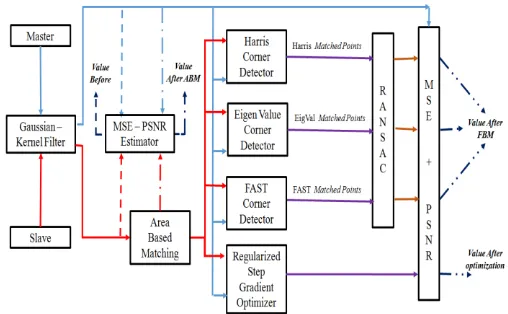
A. Proposed Framework
The framework of this paper is illustrated as shown in figure 2 where a combination between area based matching (ABM) technique, represented in correlation method, as a coarse co-registration process and a feature based matching (FBM) technique, represented in utilizing regular step gradient descent optimizer; harris detector; eigenvalues detector; and FAST detector, as a fine co-registration process. After acquiring both master and slave images, MSE; PSNR; and Shift between input images are estimated before starting the registration process.
Fig.2. Illustration Framework of co-registration process
Applying the correlation method as an area based matching (ABM) technique in order to perform the coarse co-registration, then; MSE, PSNR, and Shift between input images are estimated. The shift between the input images will be (0,0), but in fact; there is a sub-pixel shift between images. This sub-pixel shift will be recovered using the fine co-registration process which is represented, as mentioned above, utilizing the regular step gradient descent optimizer; harris detector; eigenvalues detector; and FAST detector. Both master and Shifted slave images are passed into two ways: (1) a group of different detector and (2) regular step gradient descent (RSGD) optimizer.
W.r.t the usage of different detectors, the common used feature detectors (Harris [30], Minimum Eigenvalues [31], and FAST [32]) is used to evaluate the performance of the demonstrated algorithm. Harris corner detector was developed to recover the limitations of Moravec's detector [33]. Shi, Tomasi [31], known as minimum eigenvalues corner detector, was proceeded as an optimization process depending on the concept of harris detector allowing utilization of the eigenvalues, minimum, for differentiation leading to control and simplify the calculations of harris. Based on [34] Features from Accelerated Segment Test (FAST) [32] was proposed as one scale corner detector where anchor points are dedicated by forming a test for all image pixels considering a circle, called bresenham circle, of diameter of sixteen pixels around the key-point. Although
there is a similarity between both FAST and SUSAN [35] detectors from point of operational view, FAST detectors utilizes a narrow window size beside the actuality that not all of pixels are examined but only somewhat of these are investigated. Finally, FAST corner detector can be considered to be close to local binary pattern LBP [2-14].
The regular step gradient descent (RSGD) optimizer performs a certain procedures based on specific steps in order to complete the fine registration process [15, 17, 20].
[image:4.595.308.549.115.683.2]After applying the fine registration process using the two ways, also; MSE, PSNR, and Shift between input images (master and registered) are estimated. The shift between the images will be (0,0) accurately.
Fig. 3. Description of RANSAC Concept
B. Experimental Dataset, Results, and Analysis
The working on dataset contains 4 pairs of SAR images where one pair is simulated and the other three pairs are real images, captured using different sensors and have different sizes and different pixel shift as shown in Table 1. Each used detector (harris; minimum eigenvalues; and FAST feature detectors) has its own specifications w.r.t the used pair of image while keeping the characteristics of the regular step gradient descent optimizer unchanged for almost pairs of images, as shown in Table 2. For evaluating the performance of the demonstrated method, harris; minimum eigenvalues; and FAST feature detectors will be used. Cross correlation peak is represented for all the steps before, during, and after the co-registration process. W.r.t. the image Pair number 1(Simulated), the experimental results are shown in Tables 3 and the cross correlation peak between the input images is represented in figure 4. Harris and FAST corner detectors fail to extract corners. W.r.t. the image Pair number 2 (Las Vegas, USA), the experimental results are shown in Tables 4 and the cross correlation peak between the input images is represented in figure 5. W.r.t. the image Pair number 3 (Part of China), the experimental results are shown in Tables 5 and the cross correlation peak between the input images is represented in figure 6. W.r.t. the image Pair number 4 (Aswan Dam, Egypt), the experimental results are shown in Tables 6 and the cross correlation peak
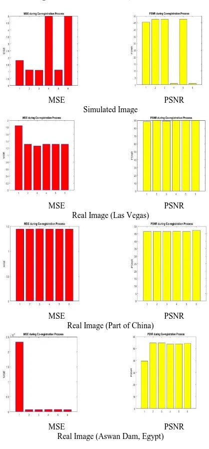
between the input images is represented in figure 7.The estimated mean square error (MSE) and peak signal to noise ratio (PSNR) for each pair of images is depicted in figure 8.
TABLE1
DATASET AND DETECTORS SPECIFICATIONS
Specifications
Pair No. (1) (2) (3) (4)
Image Type Simulated Real Real Real
Sensor - ERS 1, 2 ERS 1, 2 Terra-X
Pixel Shift 0, 1 199, 6 0, 0 60, -40
Size 1502*1148 9000*2500 3000*3000 1800*3600
TABLE2
SPECIFICATIONS OF USED DETECTORS AND OPTIMIZER
Specifications
Pair No. -1 -2 -3 -4 Detectors
Threshol d
Harris 1.00E-0 8
1.00E-0 6
1.00E-0 6
1.00E -06 Eigenvalue
s
1.00E-0 6
1.00E-0 6
1.00E-0 6
1.00E -06 FAST 5 1200 100 500 RSGD Magnitude
Tolerance
1.00E-0 6
1.00E-0 6
1.00E-0 6 10 Optimize
r
Min. Step Length
1.00E-0 5
1.00E-0 5
1.00E-0 5 100 Max. Step
Length
4.00E-0 4
4.00E-0 4
4.00E-0 4 400 Max.
Iterations 300 300 300 500 Relaxation
Factor
5.00E-0 2
5.00E-0 2
5.00E-0 2
5.00E -02
TABLE3
RESULTS OF IMAGE PAIRS NO.1(SIMULATED)
Pair No. (1) Parameters Harris FAST
Eigen
value RSGD
Before
Shift Peak
Position 0, 1 MSE 1.815 PSNR 45.541
ABM
Shift Peak
Position 0, 0 MSE 1.124 PSNR 47.622
FMB
Maximum
Corners 5000 - Mat Pts - - 70 - Shift Peak
[image:4.595.61.276.138.441.2] [image:4.595.309.546.452.694.2]International Journal of Innovative Technology and Exploring Engineering (IJITEE) ISSN: 2278-3075, Volume-9 Issue-2, December 2019
TABLE4
RESULTS OF IMAGE PAIRS NO.2(REAL) Pair No. (2)
Parameters Harris FAST Eigen
value RSGD
Before
Shift Peak
Position 199, 6 MSE 1.847 PSNR 88.348
ABM
Shift Peak
Position 0, 0 MSE 1.316 PSNR 89.818
FMB
Maximum
Corners 5000 - Mat Pts 46 9 51 - Shift Peak
Position 0, 0 0, 0 0, 0 0, 0 MSE 1.3159 1.3163 1.3161 1.266 PSNR 89.819 89.815 89.813 *89.837
* is best one
TABLE5
RESULTS OF IMAGE PAIRS NO.3 (REAL) Pair No. (3)
Parameters Harris FAST
Eigen
value RSGD
Before
Shift Peak
Position 0, 0 MSE 1.446 PSNR 46.53
ABM
Shift Peak
Position 0, 0 MSE 1.446 PSNR 46.53
FMB
Maximu
m Corners 5000 - Mat Pts 156 393 156 - Shift Peak
Position 0, 0 0, 0 0, 0 0, 0 MSE 1.446 1.447 1.446 1.448 PSNR 46.78 *47.376 46.559 46.523 * is best one
TABLE6
RESULTS OF IMAGE PAIRS NO.3 (REAL)
BEFORE CO-REGISTRATION AFTER APPLYING ABM
REGULAR STEP GRADIENT DESCENT OPTIMIZER
EIGENVALUES DETECTOR
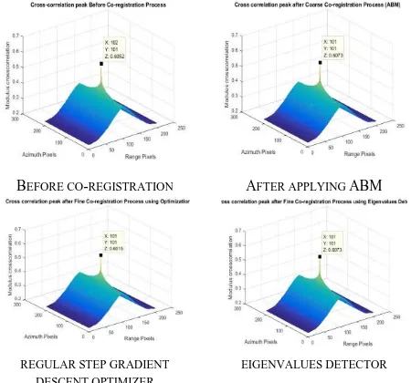
Fig. 4. Cross correlation Peak of Simulated Image: 1) before registration, 2) after applying ABM, and 3) after applying FBM using
a) regular step gradient descent optimizer; b) eigenvalues detector
Regular step gradient descent optimizer
Harris detector
[image:5.595.80.539.46.842.2]Eigenvalues detector FAST detector
Fig. 5. Las Vegas): 1 After applying FBM using a) regular step gradient descent optimizer; b) harris detector, c) eigenvalues detector, and d)
FAST detector
Regular step gradient descent optimizer
Harris detector
Eigenvalues detector FAST detector
Fig. 6. Part of China): 1After applying FBM using a) regular step gradient descent optimizer; b) harris
[image:5.595.306.531.52.262.2] [image:5.595.307.533.55.508.2] [image:5.595.56.280.69.282.2]Regular step gradient descent optimizer
Harris detector
[image:6.595.59.277.50.250.2]Eigenvalues detector FAST detector
Fig. 7. Aswan Dam, Egypt): 1 Part of China): 1After applying FBM using a) regular step gradient descent optimizer; b) harris detector, c)
eigenvalues detector, and d) FAST detector
MSE PSNR Simulated Image
MSE PSNR Real Image (Las Vegas)
MSE PSNR Real Image (Part of China)
MSE PSNR Real Image (Aswan Dam, Egypt)
Fig. 8. MSE and PSNR for all the tested images of during Co-registration process where x-axis label 1) before co-registration, 2) after applying ABM, 3) after applying gradient Optimizer as FBM, 4) after applying harris detector as FBM, 5) after applying Eigenvalues
detector as FBM, and 6) after applying FAST detector as FBM
IV. CONCLUSION
The exhibited dataset permits to conduct two forms of experiments on SAR images: (1) simulated and real with approximately no pixel shift and (2) real with somewhat large pixel shift. The paper demonstrates a dynamic method to improve the registration process of SAR images. A combination between area based matching (ABM) technique, represented in correlation method acting as a coarse co-registration process and utilizing regular step gradient descent (RSGD) optimizer to act as fine co-registration step. Applying on 4 pairs of SAR images acquired from different sensors with different sizes and different pixel shift shows that the demonstrated method gives a reasonable results, if not better, compared to the commonly used feature detectors (Harris, Minimum Eigenvalues, and FAST).
REFERENCES
1. M. Hassaballah, Hammam A. Alshazly and Abdelmgeid A. Ali (2019) Analysis and Evaluation of Keypoint Descriptors for Image Matching. In: Recent Advances in Computer Vision Theories and Applications vol. 804, pp 113-140 . https://doi.org/10.1007/978-3-030-03000-1 2. Ertugrul BAYRAKTAR, Pinar BOYRAZ (2017) Analysis of feature
detector and descriptor combinations with a localization experiment for various performance metrics. Turkish Journal of Electrical Engineering & Computer Sciences, vol. 25, pp 2444-2454. https://doi.org/10.3906/elk-1602-225
3. Abdelhameed S. Eltanany, M. S. Elwan, and A. S. Amein (2019) Key Point Detection Techniques. Proc. of the International Conference on Advanced Intelligent Systems and Informatics. In: Advances in Intelligent Systems and Computing series, vol. 1058, chapter 82. to be published.
4. Reshmi Krishnan, Anil. A. R., (2016) A Survey on Image Matching Methods. International Journal of Latest Research in Engineering and Technology (IJLRET), vol. 2(1), pp 58-61.
5. Niangang Jiao, Wenchao Kang, et al (2017) A Novel and Fast Corner Detection Method For SAR Imagery. International Archives of the Photogrammetry, Remote Sensing and Spatial Information Sciences, vol. XLII–2/W7, pp 605-608. https://doi.org/10.5194/isprs-archives-XLII-2-W7-605-2017. 6. A.A. Karim, E. F. Nasser (2017) Improvement of Corner Detection
Algorithms (Harris, FAST and SUSAN) Based on Reduction of Features Space and Complexity Time. Engineering & Technology Journal, vol. 35, Part B(2), pp 112-118.
7. Wong, Alexander, David A. Clausi (2007) ARRSI: automatic registration of remote-sensing images. IEEE Transactions on Geoscience and Remote Sensing, vol. 45(5), pp 1483-1493. https://doi.org/ 10.1109/TGRS.2007.892601.
8. M. Hassaballah, Aly Amin Abdelmgeid and Hammam A. Alshazly (2016) Image Features Detection, Description and Matching. In: Image Feature Detectors and Descriptors: Foundations and Applications, vol.630, pp11-45. https://doi.org/10.1007/978-3-319-28854-3. 9. Arthur Ardeshir Goshtasby (2017) Theory and Applications of Image
Registration. 1st edn, JohnWiley & Sons, USA.
10. Ardeshir Goshtasby (2012) Image Registration Principles, Tools and Methods. Advances in Computer Vision and Pattern Recognition. Springer-Verlag London. https://doi.org/10.1007/978-1-4471-2458-0 11. Bentoutou, Youcef, et al. (2005) An automatic image registration for
applications in remote sensing. IEEE Transactions on Geoscience and Remote Sensing, vol. 43(9), pp 2127-2137. https://doi.org/ 10.1109/tgrs.2005.853187.
12. E.R. Davies (2018) Computer Vision Principles, Algorithms Applications, Learning, 5th edn, Elsevier Inc.
13. Victor T. Wang (2018) Registration of Synthetic Aperture Imagery using Feature Matching. University of Canterbury, Christchurch, New Zealand.
14. K Y Kok and P Rajendran (2018) Validation of Harris Detector and Eigen Features Detector.
[image:6.595.58.267.290.738.2]International Journal of Innovative Technology and Exploring Engineering (IJITEE) ISSN: 2278-3075, Volume-9 Issue-2, December 2019
370. https://doi.org/ 10.1088/1757-899X/370/1/012013.
15. Shadrack Mambo (2019) Optimization and Performance Evaluation in image registration technique. Tshwane University of Technology. 16. Catalina-Lucia Cocianu and Alexandru Stan. (2019) New
Evolutionary-Based Techniques for Image Registration. Applied Sciences-Open Access Journal, vol. 9(1), 176. https://doi.org/10.3390/app9010176.
17. Bruno Conejo (2018) Optimization techniques for image registration applied to remote sensing. University Paris-East.
18. Guoli Song, Jianda Han, et al (2017) A Review on Medical Image Registration as an Optimization Problem. Current Medical Imaging Reviews, vol. 13(3), pp 274-283. https://doi.org/ 10.2174/1573405612666160920123955.
19. Yuchuan Qiao (2017) Fast optimization methods for image registration in adaptive radiation therapy. Geboren te Hubei, China. 20. Daniel James Taylor (2018) Optimization Methods and Applications
on problem solving with MATLAB in the presence of Randomness. University of Chester.
21. Meifeng Shi, Zhongshi He, Ziyu Chen, Hang Zhang (2016) A Novel Multi-objective Optimization-based Image Registration Method. The Genetic and Evolutionary Computation Conference, pp 605-612. https://doi.org/10.1145/2908812.2908931.
22. PN Maddaiah , PN Pournami , VK Govindan (2014) Optimization of Image Registration for Medical Image Analysis. International Jour. of Computer Science and Information Technologies, vol. 5(3), pp 3394-3398.
23. Viktor Vegh, Zhengyi Yang, Quang M. Tieng , et al (2010) Multimodal Image Registration Using Stochastic Differential Equation Optimization. 17th International Conference on Image Processing, Proceedings of IEEE, pp 4385-4388. https://doi.org/10.1109/ICIP.2010.5653395.
24. Van der Bom I., Klein S., et al (2011) Evaluation Of Optimization Methods for Intensity-based 2d-3d Registration in X-ray Guided Interventions. International Society for Optics and Photonics, Proc. of SPIE, Medical Imaging, vol. 7962, pp 23(1-15). https://doi.org/10.1117/12.877655.
25. Klein S. (2008) Optimization methods for medical image registration. Image Sciences Institute, Utrecht University, Netherlands.
26. Gupta A., Verma H.K., & Gupta S. (2012) Technology and research developments in carotid image registration. Journal of Biomedical Signal Processing and Control, vol. 7, pp 560-570. https://doi.org/ 10.1016/j.bspc.2012.05.003.
27. Ying Chen, Richard R. Brooks,S. Sitharama yengar (2002) Efficient Global Optimization for Image Registration. IEEE Transactions on knowledge and data engineering, vol. 14(1), pp 79-92.
28. Sebastian Ruder (2017) An overview of gradient descent optimization algorithms. Cornell university. arXiv:1609.04747v2.
29. Meza, J. C. (2010) Steepest descent. Wiley Interdisciplinary Reviews: Computational Statistics Journal, vol. 2(6), pp 719-722. https://doi.org/10.1002/wics.117
30. C. Harris and M. Stephens (1988) A combined corner and edge detector. Alvey Vision Conference, pp 147-151. https://doi.org/10.5244/C.2.23.
31. Shi, J., and C. Tomasi (1994) Good Features to Track. Proc. of the IEEE Conference on Computer Vision and Pattern Recognition (CVPR94) Seattle. https://doi.org/10.1109/CVPR.1994.323794. 32. Rosten, E., Drummond, T. (2006) Machine learning for high speed
corner detection. 9th European Conference on Computer Vision (ECCV’06), vol 3951, pp 430-443. https://doi.org/10.1007/11744023_34.
33. Moravec, H.P. (1977) Towards automatic visual obstacle avoidance. Proc. of the 5th International Joint Conference on Artificial Intelligence (IJCAI), vol. 2, pp 584-594.
34. Förstner, W; Gülch (1987) A Fast Operator for Detection and Precise Location of Distinct Points, Corners and Centers of Circular Features. International Society for Photogrammetry and Remote Sensing ISPRS, Intercommision Workshop.
AUTHORSPROFILE
Mohammed Safy received B.Sc. degrees in Electrical Engineering from Military Technical College (MTC), Cairo, Egypt, 2001. Also, He received M.Sc. degree "Micro-machined bolometer for thermal imaging" from MTC, 2008. and Ph.D. degree "High Resolution Digital Terrain - Elevation Data For Intelligence Gathering and
Tactical Target", University of Xian, China, 2014. His research interests include Image processing, Air and Space-borne InSAR, InSAR performance estimation, Optimization methods in SAR image registration.
Abdelhameed S. Eltanany received B.Sc. degree in Electrical Engineering from Military Technical College (MTC), Cairo, Egypt, 2001. Also, He received M.Sc. degree "Co-registration Techniques of Satellite SAR Images for Earth Observation" from MTC, 2015. He is currently pursuing Ph.D. degree in MTC, Cairo, Egypt. His research and interests are focusing on SAR Images Features Matching and Registration.