Copyright to IJAREEIE DOI:10.15662/IJAREEIE.2015.0411031 8756
Loss Reduction of Distribution System by
Capacitor Placement Using Ant Colony
Search Algorithm
K Naveenkumar1, K Rajavelu2, R Kalaiselvi3,
Assistant Professor, Dept. of EEE, CKCET, Cuddalore, Tamilnadu, India1 Assistant Professor, Dept. of EEE, CKCET, Cuddalore, Tamilnadu, India 2 Assistant Professor, Dept. of EEE, CKCET, Cuddalore, Tamilnadu, India 3
ABSTRACT: The voltage instability occurs in power system when the system is unable to maintain an acceptable voltage profile under an increasing load demand and / or configuration changes the operating conditions of the presents day distribution systems are closer to the voltage stability boundaries due to the ever increasing load demand. Capacitors have long been used in power system for providing reactive power support, which reduces power and energy losses, increase the available capacity of the feeders, and improves the feeder voltage profile. In this work, a method employing the Ant Colony Search Algorithm (ACSA) has been developed for the capacitor placement in a view to enhance voltage stability besides improving voltage profile and reducing losses. The proposed technique has been tested on 28 node distribution systems. It has been found that the proposed method provides highly satisfactory results.
KEYWORDS: Ant colony search algorithm, Capacitor placement, Voltage Stability, Distribution system
I. INTRODUCTION
The present day electric power systems are operated in stressed conditions because the transmission lines of the system are operated below the surge impedance loading to meet the ever increasing load. Recently, there has been a growing interest in optimizing the operation of distribution networks, which are in general configured radically. These systems have a combination of loads like industrial, commercial and domestic loads; and distinct changes in load level may occur at any time and at any part of the system. The main factor causing voltage instability is the inability of the system to meet the demand for reactive power in the heavily stressed systems, which prevents it from maintaining the desired voltages. The other factors contributing to voltage collapse are generator reactive power/voltage control limits, load characteristics; characteristics of reactive compensation devices and the actions of voltage control devices such as transformer under load tap changers.When a power system is operating close to its stability limits, it is essential for the system operator have a clear knowledge of its operating state. They are looking for tools that can enhance their understanding of where the system is operating with respect to the point of voltage collapse.
A number of approaches besides various indices have been suggested for predicting voltage instabilities, such as singular value decomposition, L-index, PV, and QV curves, eigen value decompositions, V-Q sensitivity and energy based method, in the literature. Most of the methods require significantly large computations and are not efficient enough for real time use in energy management systems.
It is therefore essential that efficient and economically justified solution techniques for avoiding voltage instability problem be developed. Obviously, an effective control measure is the most appropriate strategy to prevent voltage collapse.
Generally capacitors have been commonly employed to provide reactive power compensation in distribution system. They are reduces the power loss and to maintain the voltage profile within the acceptable limits. They benefits of the compensation depend on how capacitors are placed in the system, specifically on the location on the sides of the added capacitors.
Variety of method have been developed to solving optimal capacitor placement problems by employing mathematical programming techniques
1. Ant Colony Search Algorithm 2. Simulated Annealing
3. Genetic Algorithm
4. Evolutionary Programming 5. Particle Swarm Optimization
In this work, Ant Colony Search Algorithm has been used to optimal capacitor placement. The following are the disadvantage of corresponding techniques when compared to Ant Colony Search Algorithm. Repeatedly annealing with a 1/log k schedule is very slow, especially if the cost function is expensive to compute. For problems where the energy landscape is smooth, or there are few local minima, SA is overkill --- simpler, faster methods (e.g., gradient descent) will work better. But usually don't know what the energy landscape is. Heuristic methods, which are problem-specific or take advantage of extra information about the system, will often be better than general methods. But SA is often comparable to heuristics. The method cannot tell whether it has found an optimal solution. Some other method (e.g. branch and bound) is required to do this.
They shows a very fast initial convergence, followed by progressive slower improvements (sometimes is good to combine it with a local optimization method). In presence of lots of noise, convergence is difficult and the local optimization technique might be useless. Models with many parameters are computationally expensive. Sometimes not particularly good models are better than the rest of the population and cause premature convergence to local minima. The fitness of all the models may be similar, so convergence is slow. Optimal solution cannot be ensured on using evolutionary programming methods. Convergence of EP techniques is problem oriented. Sensitivity analysis should be carried out to find out the range in which the model is efficient. Implementation requires good programming skill.
Lacking somewhat of a solid mathematical foundation for analysis, some limitations in real-time ED applications, such as in the 5-minute dispatch with constraints, due to relatively longer computation time (possibility for the off-line real world problems such as in the day-ahead electrically markets). Still having the problems of dependency on initial conditions, parameter values, difficulty in finding the optimal design parameters, stochastic characteristics of the final outputs.
Advantage
1. Ant colony search algorithm are parallel search and optimization capabilities
2. Ant colony search algorithm are applied to the capacitor placement problems in which switches are discrete 3. The state transition rule, global and local updating rules are introduced to ensure the optimal solution
II. LITERATUREREVIEW
A variety of methods have been devoted to solving optimal capacitor placement problems by employing mathematical programming techniques. Grainger et al. [1], [2] formulated the problem as a nonlinear programming problem by treating the capacitor sizes and the locations as continuous variables.Duran [3] considered the capacitor sizes as discrete variables and used dynamic programming to find the optimal solution.
Copyright to IJAREEIE DOI:10.15662/IJAREEIE.2015.0411031 8758
In [10], the authors proposed a single dynamic data structure for an evolutionary programming (EP) algorithm to solve the optimal capacitor allocation. Civanlar et al. [11] conducted the early research on feeder reconfiguration for loss reduction.. In [12], Baran et al. modeled the problem of loss reduction and load balancing as an integer programming problem.In [13], the authors used a genetic algorithm to look for the minimum loss configuration. In [14], the authors presented the use of the power flow method based on a heuristic algorithm to determine the minimum loss configuration for radial distribution networks. In [15], [16], the authors proposed a solution procedure which employed simulated annealing to search for an acceptable non-inferior solution.
In [17], the authors proposed a mixed-integer hybrid differential evolution to solve network reconfiguration. In [18], the authors proposed an economic operation model to solve distribution network configuration. In [19], the authors proposed a tree encoding and two genetic operators to improve the EA performance for network reconfiguration problems.
In [20], the authors proposed a fuzzy multiobjective approach to solve the network reconfiguration problem. However, most of the previous studies handled capacitor placement problems without consideration of feeder reconfigration [1]–[10], or handled feeder reconfiguration problems without consideration of capacitor placement [11]– [20]. They dealt with the feeder reconfiguration and capacitor placement in a separate manner [1]–[20], which may result in unnecessary losses and cannot yield the minimum loss configuration. On the other hand, there are only few examples in the literature on loss minimization applying heuristic techniques for feeder reconfiguration and capacitor placement [21]–[24].
III. ANT COLONY SEARCH ALGORITHM
In this work, Ant Colony Search Algorithm has been used to optimal capacitor placement. This algorithm is a member of ant colony algorithms family, in swarm intelligence methods, and it constitutes some metaheuristic optimizations. Initially proposed by Marco dorigo in 1992 in his PhD thesis. The first algorithm was aiming to search for an optimal path in a graph; based on the behavior of ants seeking a path between their colony and a source of food. The original idea has since diversified to solve a wider class of numerical problems, and as a result, several problems have emerged, drawing on various aspects of the behavior of ants.
In the real world, ants (initially) wander randomly, and upon finding food return to their colony while laying down pheromone trails. If other ants find such a path, they are likely not to keep traveling at random, but to instead follow the trail, returning and reinforcing it if they eventually find food.
Over time, however, the pheromone trail starts to evaporate, thus reducing its attractive strength. The more time it takes for an ant to travel down the path and back again, the more time the pheromones have to evaporate. A short path, by comparison, gets marched over faster, and thus the pheromone density remains high as it is laid on the path as fast as it can evaporate. Pheromone evaporation has also the advantage of avoiding the convergence to a locally optimal solution. If there were no evaporation at all, the paths chosen by the first ants would tend to be excessively attractive to the following ones. In that case, the exploration of the solution space would be constrained.
Thus, when one ant finds a good (i.e., short) path from the colony to a food source, other ants are more likely to follow that path, and positive feedback eventually leads all the ants following a single path. The idea of the ant colony algorithm is to mimic this behavior with "simulated ants" walking around the graph representing the problem to solve.
A.ANT COLONY BEHAVIOR
The ACSA imitates the behaviors of real ants. As is well known, real ants are capable of finding the shortest path from food sources to the nest without using visual cues. Also, they are capable of adapting to changes in the environment, For example, finding a new shortest path once the old one is no longer feasible due to a new obstacle. Moreover, the ants manage to establish shortest paths through the medium that is called “pheromone.” The pheromone is the material deposited by the ants, which serves as critical communication information among ants, thereby guiding the determination of the next movement. Any trail that is rich of pheromone will thus become the goal path.
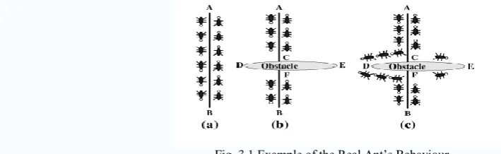
The process is illustrated by Fig. 3.1. In Fig. 3.1(a), the ants are moving from food Source A to the nest B on a straight line. Once an obstacle appears as shown in Fig. 3.1(b), the path is cut off. The ants will not be able to follow the original trail in their movements. Under this situation, they have the same probability to turn right or left. But after some time the path CD will have more pheromones and all the ants will move in the path ACD. As the ants from C to reach F through D will reach quicker than that of the ants through E, i.e., CEF.
increasingly guided to move on the shorter path. Due to this autocatalytic process, very soon all ants will choose the shorter path. This behavior forms the fundamental paradigm of the ant colony search algorithm.
Fig. 3.1 Example of the Real Ant’s Behaviour
As illustrated in Fig. 3.1, by the guidance of the pheromone intensity, the ants select preferable path. Finally, the favorite path rich of pheromone becomes the best tour, the solution to the problem. This concept develops the emergence of the ACSA method. At first, each ant is placed on a starting state. Each will build a full path, from the beginning to the end state, through the repetitive application of state transition rule. While constructing its tour, an ant also modifies the amount of pheromone on the visited path by applying the local updating rule. Once all ants have terminated their tour, the amount of pheromone on edge is modified again through the global updating rule.
In other words, the pheromone updating rules are designed so that they tend to give more pheromone to paths which should be visited by ants. In the following, the state transition rule, the local updating rule and the global updating rule are briefly introduced.
B State Transition Rule
The state transition rule used by the ant system, called a random-proportional rule, is given by the following, which gives the probability with which ant k in node i chooses to move to node j :
pk i, j =
τ i, j [η i, j ]β τ i, m [η i, m ]β
mϵJk(i)
, if j ϵ Jk(i)
0,
Where,
τ - The pheromone which deposited on the edge between node i and node j. η - The inverse of the edge distance.
Jk (i) - The set of nodes that remain to be visited by ant k positioned on node i. β -Parameter which determines the relative importance of pheromone versus distance.
Equation indicates that the state transition rule favors transitions toward nodes connected by shorter edges and with large amount of pheromone.
C Local Updating Rule
While constructing its tour, each ant modifies the pheromone by the local updating rule. This can be written as follows:
τ i, j = 1 − ρ τ i, j + ρτο Where,
τo - The initial pheromone value. ρ -A heuristically defined parameter.
The local updating rule is intended to shuffle the search process. Hence the desirability of paths can be dynamically changed. The nodes visited earlier by a certain ant can be also explored later by other ants. The search space can be therefore extended. Furthermore, in so doing, ants will make a better use of pheromone information. Without local updating all ants would search in a narrow neighborhood of the best previous tour.
D Global Updating Rule
Copyright to IJAREEIE DOI:10.15662/IJAREEIE.2015.0411031 8760
τ i, j = 1 − σ τ i, j + σδ−1
Where,
δ- The distance of the globally best tour from the beginning of the trail. σ Є [0,1]- The pheromone decay parameter.
This rule is intended to make the search more directed; therefore the capability of finding the optimal solution can be enhanced through this rule in the problem solving process.
E ALGORITHM FOR PROPOSED METHOD
The main computational processes are briefly stated below.
Step 1) Initiation
At first, the colonies of ants are randomly selected and which estimated the initial fitness in the different permutations. A random number generator can be employed to generate the number of ants within the feasible search space. In addition, these ants are positioned on different nodes, while the initial pheromone value of τo is also given at this step.
.Step 2) Estimation of the fitness
When all ants have finished a tour, the fitness of each ant is estimated. Usually, fitness function is defined to estimate the performance of each ant. In this step, the fitness of all ants is assessed based on the corresponding objective function, which is expressed as (1). Then, the pheromone can be added to the particular direction in which the ants have chosen. At this stage, a roulette selection algorithm can be employed based on the computed fitness. Then, by spinning this designated roulette, a new permutation of pheromone associated with different paths is formed. In other words, based on a roulette selection method, a path (fitness) with higher amount of pheromone will easily be selected as a new path. Hence, it would be more suitable for guiding the ants to the direction.
Step 3) Ant Placement and Reconfiguration
The ant placement and reconfiguration are based on the level of pheromone and distance. As (4.1) shows, each ant selects the next node to move taking into account the τ (i,j) and η (i,j) values. A greater η (i,j) means that there has been a lot of traffic on this edge; hence, it is more desirable to approach the optimal solution. On the other hand, a greater τ
(i,j) indicates that the closer node should be chosen with a higher probability. In the capacitor placement and network reconfiguration study, this can be seen as the difference between the original total power loss and the new total power loss. Therefore, in this step, the ant placement and reconfiguration process helps convey ants by selecting directions based on these two parameters.
Step 4) Local/Global Updating Rule
While constructing a solution of the capacitor placement and network reconfiguration problem, ants visit edges and change their pheromone level by applying the local updating rule of (10). Its purpose is not only broadening the search space, but dynamically increasing the diversity of ant colony. After n iterations, all ants have completed a tour; the pheromone level is updated by applying the global updating rule of (11) for the trail that belongs to the best selected path. Therefore, according to this rule, the shortest path found by the ants is allowed to update its pheromone. Also, this shortest path will be saved as a record for the later comparison with the succeeding iteration.
Step 5) Termination of the Algorithm
End the process if “the maximum iteration number is reached” or “all ants have selected the same tour” is satisfied; otherwise repeat the outer loop. In addition, the number of ants and the number of iterations were experimentally determined. All the tour visited by ants in each iteration should be evaluated. If a better path found in the process, it will be saved for later reference.
IV. PROPOSEDMETHOD
secondary substation bus s/s) distribution feeder as shown in Fig. 8, and each bus has five available capacitor sizes to choose from. Consequently, a 5* 5 matrix can be formed, as shown in Fig. 9, to express what is mentioned above.
S/S 1 2 3 4 5
Fig.2 Five-Bus Distribution Feeder
The path indicated means capacitor sizes 3, 2, 3, 1, and 4 have been chosen for buses 1, 2, 3, 4, and 5, respectively. In terminology of the ACSA, it is described that each bus has five nodes (i.e., five available capacitor sizes) and from each bus to its next bus there are five edges. For example, the path indicated in Fig. 9 has five edges, there are edge (s/s→ node 3 of bus 1) (not indicated in the figure), edge (node 3 of bus 1→ node 2 of bus 2), edge (node 2 of bus 2→ node 3 of bus 3), edge (node 3 of bus 3 → node 1 of bus 4), and edge (node 1 of bus 4→ node 4 of bus 5), Thus, there are five edge distances and five amounts of pheromone corresponding to these five edges.
Fig.3 A 5*5 Capacitor Placement Space
Assume that there are five ants moving from bus 1 to bus 5 with five different paths indicated as [2 1 2 1 3; 2 1 3 2 5; 1 2 3 4 3; 3 5 4 1 1; 4 1 3 5 4]. For example, the path for ant 1 is node 2 of bus 1→ node 1 of bus 2→ node 2 of bus 3 → node 1 of bus 4 → node 3 of bus 5. In the capacitor placement problem, this path means that buses 1 to 5 choose capacitor sizes 2, 1, 2, 1, and 3, respectively. Furthermore, assume that the path distances for these five paths are 200, 250, 300, 350, and 400, indicated as [200 250 300 350 400]. Here, the path distance is the sum of the edge distances of itself. For example, path 1 has a path distance of 200, which is the sum of the edge distances of edge (s/s → node 2 of bus 1), edge (node 2 of bus 1 node 1 of bus 2), edge (node 1 of bus 2 node 2 of bus 3), edge (node 2 of bus 3 → node 1 of bus 4), and edge (node 1 of bus 4 → node 3 of bus 5). In the capacitor placement problem, path 1 having a path distance of 200 means that the for the capacitor placement [2 1 2 1 3] is 200.The average edge distances for these five paths are calculated as [200; 250; 300; 350; 400] / 5 = [40; 50; 60; 70; 80], because each path has five edge distances. The inverse of the average edge distance is subsequently determined as η = [1/40; 1/50; 1/60; 1/70; 1/80] . And the distance of the globally best tour is δ = [200 250 300 350 400]. Moreover, let the initial τ(i,j) = 0,τo = 0.1,ρ = 0.05, σ = 0.1 and β = 1.
By applying the local updating rule of , the local τ(i,j) is determined. This local τ(i,j) is then substituted into the global updating rule of to obtain the global . Finally, this global τ(i,j), η , and β are substituted into the state transition rule of to determine the probability of these five available capacitor sizes to be selected for placement by these five buses.
Copyright to IJAREEIE DOI:10.15662/IJAREEIE.2015.0411031 8762
From the probability matrix shown above, it can be seen that path [2 1 3 1 3] has the highest probability to be selected. Moreover, path [2 1 3 1 3] is very close to path [2 1 3 1 3] , which has the lowest cost of 200 assumed above. Similar search procedures are repeated to reach a final convergent solution.
V. CASESTUDY
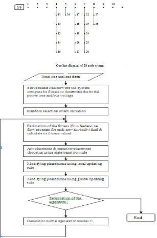
The Ant Colony Search Algorithm has based tested on 28 node test systems. The one line diagram of the test systems are given in below.
The results are obtained and presented in table1. The analysis of these results indicates that the Ant Colony Search Algorithm provides optimal locations of capacitor support to be provided to improve voltage stability. This method not only enhances voltage stability but also minimizes the losses and improves voltage profile. This method is suitable for practical implementation.
VI. CONCLUSION
A simple optimal capacitor placement for voltage stability enhancement of distribution system by using Ant Colony Search Algorithm has been suggested in this thesis. This method is simple and is based on a voltage stability index. This method not only improves voltage stability but also reduces network losses and enhances voltage profile effectively. This Algorithm is suitable for practical implementation on systems of any size.
SYSTEM DESCRIPTION BEFORE CAPACITOR PLACEMENT AFTER CAPACITOR PLACEMENT BUS VOLTAGE 1 0.9862 0.9665 0.9523 0.9382 0.9277 0.9185 0.9160 0.9157 0.9155 0.9462 0.9444 0.9433 0.9431 0.9428 0.9371 0.9259 0.9249 0.9232 0.9224 0.9217 0.9156 0.9141 0.9129 0.9126 0.9125 0.9155 0.9154 1 0.9873 0.9687 0.9557 0.9427 0.9333 0.9252 0.9237 0.9245 0.9252 0.9508 0.9500 0.9500 0.9507 0.9515 0.9426 0.9325 0.9325 0.9319 0.9320 0.9324 0.9233 0.9238 0.9226 0.9234 0.9242 0.9243 0.9251
Vmax 1 1
Vmin 0.9125
(BUS 26)
Copyright to IJAREEIE DOI:10.15662/IJAREEIE.2015.0411031 8764
REFERENCES
[1] J. J. Grainger and S. H. Lee, “Optimum size and location of shunt capacitors for reduction of losses on distribution feeders,” IEEE Trans.Power App. Syst., vol. PAS-100, pp. 1105–1118, Mar. 1981.
[2] J. J. Grainger and S. H. Lee, “Capacity release by shunt capacitor placement on distribution feeder: A new voltage-dependent model,” IEEE Trans. Power App. Syst., vol. PAS-101, no. 5, pp. 1236–1244, May 1982.
[3] H. Duran, “Optimum number, location, and size of shunt capacitors in radial distribution feeder: A dynamic programming approach,” IEEE Trans. Power App. Syst., vol. PAS-87, no. 9, pp. 1769–1774, Sep. 1968.
[4] Y. Baghzouz and S. Ertem, “Shunt capacitor sizing for radial distribution feeders with distorted substation voltages,” IEEE Trans. Power Del., vol. 5, no. 2, pp. 650–657, Apr. 1990.
[5] J. L. Bala, P. A. Kuntz, and R. M. Taylor, “Sensitivity-based optimal capacitor placement on a radial distribution feeder,” in Proc. 1995 Northcon 95 IEEE Technical Application Conf., pp. 225–230.
[6] H. D. Chiang, J. C. Wang, O. Cocking, and H. D. Shin, “Optimal capacitors placements in distribution systems, part I: A new formulation of the overall problem,” IEEE Trans. Power Del., vol. 5, no. 2, pp.634–642, Apr. 1990.
[7] S. Sundhararajan and A. Pahwa, “Optimal selection of capacitor for radial distribution systems using a genetic algorithm,” IEEE Trans. Power Syst., vol. 9, no. 3, pp. 1499–1507, Aug. 1994.
[8] M. A. S. Masoum, M. Ladjevardi, A. Jafarian, and E. F. Fuchs, “Optimal placement, replacement and sizing of capacitor banks in distorted distribution networks by genetic algorithms,” IEEE Trans. Power Del.,vol. 19, no. 4, pp. 1794–1801, Oct. 2004.
[9] A.Mendes, P.M. Franca, C. Lyra, C. Pissarra, and C. Cavellucci, “Capacitor placement in large-sized radial distribution networks,” Proc.Inst. Elect. Eng., Gen., Transm., Distrib., vol. 152, no. 4, pp. 496–502,Jul. 2005.
[10] B. Venkatesh and R. Ranjan, “Fuzzy EP algorithm and dynamic data structure for optimal capacitor allocation in radial distribution systems,” Proc. Inst. Elect. Eng., Gen., Transm., Distrib., vol. 153, no.1, pp. 80–88, Jan. 2006.
[11] S. Civanlar, J. J. Grainger,H.Yin, and S. S. H. Lee, “Distribution feeder reconfiguration for loss reduction,” IEEE Trans. Power Del., vol. 3, no. 3, pp. 1217–1223, Jul. 1988.
[12] M. E. Baran and F. F.Wu, “Network reconfiguration in distribution systems for loss reduction and load balancing,” IEEE Trans. Power Del.,vol. 4, no. 2, pp. 1401–1407, Apr. 1989.
[13] K. Prasad, R. Ranjan, N. C. Sahoo, and A. Chaturvedi, “Optimal reconfiguration of radial distribution systems using a fuzzy mutated genetic algorithm,” IEEE Trans. Power Del., vol. 20, no. 2, pp. 1211–1213,Apr. 2005.
[14] D. Shirmohammadi and H. W. Hong, “Reconfiguration of electric distribution networks for resistive line loss reduction,” IEEE Trans. Power Del., vol. 4, no. 2, pp. 1492–1498, Apr. 1989.
[15] H. D. Chiang and J. J. Rene, “Optimal network reconfiguration in distribution systems: Part 1: A new formulation and a solution methodology,” IEEE Trans. Power Del., vol. 5, no. 4, pp. 1902–1908, Oct.1990.
[16] H. D. Chiang and J. J. Rene, “Optimal network reconfiguration in distribution systems: Part 2: Solution algorithms and numerical results,”IEEE Trans. Power Del., vol. 5, no. 3, pp. 1568–1574, Jul. 1992.
[17] C. T. Su and C. S. Lee, “Network reconfiguration of distribution systems using improved mixed-integer hybrid differential evolution,”IEEE Trans. Power Del., vol. 18, no. 3, pp. 1022–1027, Jul. 2003.
[18] A. A. Miguel and S. H. Hernán, “Distribution network configuration for minimum energy supply cost,” IEEE Trans. Power Syst., vol. 19,no. 1, pp. 538–542, Feb. 2004.
[19] A. C. B.Delbem, A. C. P. de L. F. de Carvalho, and N.G. Bretas, “Main chain representation for evolutionary algorithms applied to distribution system econfiguration,” IEEE Trans. Power Syst., vol. 20, no. 1, pp.425–436, Feb. 2005.
[20] D. Das, “A fuzzy multiobjective approach for network reconfiguration of distribution systems,” IEEE Trans. Power Del., vol. 21, no. 1, pp.202– 209, Jan. 2006.
[21] Z. Rong, P. Xiyuan, H. Jinliang, and S. Xinfu, “Reconfiguration and capacitor placement for loss reduction of distribution systems,” in Proc.IEEE TENCON’02, 2002, pp. 1945–1949.
[22] C. T. Su and C. S. Lee, “Feeder reconfiguration and capacitor setting for loss reduction of distribution systems,” Elect. Power Syst. Res., vol.58, no. 2, pp. 97–102, Jun. 2001.
[23] G. J. Peponis, M. P. Papadopoulos, and N. D. Hatziargyiou, “Optimal operation of distribution networks,” IEEE Trans. Power Syst., vol. 11,no. 1, pp. 59–67, Feb. 1996.