.
Abstract: Photovoltaic (PV) panel produces a DC voltage as output which is always having random variations which is further required to convert into a constant DC voltage output, a Voltage Source Inverter (VSI) is the required and further another DC to AC VSI convertor required. VSI used Pulse width modulation (PWM) for switching of metal Oxide semiconductor Field Effect Transistor (MOSFET) and a very fast switch cause harmonics in the circuits, which further need to remove by filters. The available filters are good but reducing either the overall efficiency by 2-3 percentage or giving high damp at resonant frequency. that issue must be resolve, proposed work has come up with a new design in which Parallel LCL-R (PLCL-R) type filter which has high efficiency and high attenuation than previous and better response at high frequencies. Proposed design is been developed with help of Matrix laboratories (MATLAB) Simulink design, where power electronics component tool box 'sim-electronics and sim-escape' used. The results of proposed work found better then LCL filter, TRAP filter and other filters of base works.
Keywords: Voltage Source Invertors, Pulse width modulation, Photovoltaic, L-Inductor, C-Capacitor, R-Resistor
---
I.INTRODUCTION
[image:1.595.306.547.212.381.2]Inverters with PV panel are highly used in power generation and distribution systems now a days. very high switching frequency of VSI based Direct current to Direct current (DC2DC) and Direct Current to Alternate Current (DC2AC) circuits operates in ranges of frequency from 5kHz to 20kHz and this causes generation of harmonics in output AC supply this harmonics cannot be directly provide to Loading devices and must need to be remove. Selection of different harmonics filters may filter this harmonics but there are certain limitation of available filters as mentioned in table below.
Table 1 Harmonic Filter Analysis Filter Type L
Filter LC filter LCL Filter LCL-R filter TRAP filter
Damping 0 db 2.2
db 1.5 db More than 100 db 9 db
Attenuation 16 db
20 db
22 db
39 db 28 db
Maximum Freq 3.8 Khz 6.21 Khz 11.7 Khz
12 Khz 21.4 Khz
Revised Manuscript Received on August 05, 2019.
Sukriti, Electrical Engineering Department, JEC, Jabalpur, India.
Sudeep Kumar Mohaney, Electrical Engineering Department, JEC,
Jabalpur, India.
Figure 1 Harmonic Filters types II.METHODOLOGY
The harmonics are harmful for the load and it is required to have high attenuation of harmonics at the same time also there should be no damping proposed filter is a design which is using Inductor in series then Capacitor in parallel with one inductor in parallel then one Inductor in series then one capacitor in parallel with a extra variable resistor also in last one extra inductor in series. the idea is to merge TRAP filter with LCL-R and L filters in one circuits and to choose appropriate values which can cause very low damping and very high attenuation.
Proposed PLCL-R filter: In proposed work damping is a easy parallel capacitor damping and a variable resistor cause high attenuation for LCL filters, in proposed filter damping is not completely depends resistance it also depends on (C2 / C1 )
[image:1.595.51.287.598.715.2]ratio, which cause less damping with resistance.
Figure 2: Proposed PLCL-R Filter
Design Of High Attenuation and Less Damping
Filter for Renewable Energy Source with Parallel
Lrc Component
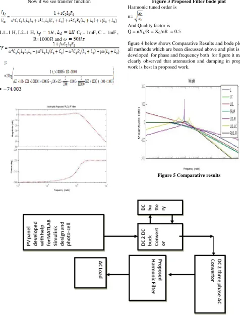
[image:1.595.312.547.605.835.2]Now if we see transfer function
L1=1 H, L2=1 H, , Cf = 1mF, C = 1mF ,
R=1000 and
Figure 3 Proposed Filter bode plot Harmonic tuned order is
n=
[image:2.595.51.528.54.682.2]And Quality factor is Q = nXL/R = XC/nR = 0.5
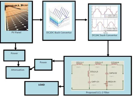
[image:2.595.324.535.213.387.2]figure 4 below shows Comparative Results and bode plot for all methods which are been discussed above and plot is been developed for phase and frequency both for figure it may be clearly observed that attenuation and damping in proposed work is best in proposed work.
Figure 5 Comparative results
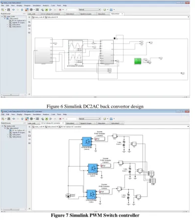
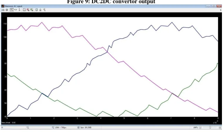
Figure 6 Flow of Proposed Design Step1: PV panel development as in new version for
MATLAB we have new features in its Simulink which is Simscape and Sim-Electronics this allows us to use photo cell
inputs (temperature, Radiation, maximum voltage etc. ) given to it.
” and to have this if significant amout for sunlight is not there it will get values from DC battery attached with it and if radiation is higher than required it will store DC power into DC battery. Step 3: Conversion DC input into 3 phase AC supply it is been done with help for Pulse Width Modulation (PWM) and for achieving this necessary a capacitor and a switch. Switch is controlled by PWM and this switch has to be switch at very high speed and this is main problem for generation for harmonics for this we necessary harmonic filter. Step 4: filtering for harmonics generated during DC 2DC and DC 2 AC conversions, it is been done with proposed filter and harmonics removed with -74 db attenuation and very small damping.
[image:3.595.69.528.317.650.2]III.RESULTS
Figure 4 shown below are block that is been developed, since design is too big so it is been shown by four various pictures. It may be seen that flow for design is exactly as explain in figure 3.17.
Figure 5 Simulink PV panal and DC2DC buck convertor design
[image:4.595.103.502.284.734.2]Figure 6 Simulink DC2AC buck convertor design
Figure 8 GUI after execution
Figure 9: DC2DC convertor output
[image:5.595.108.490.482.708.2]Figure 11:three phase filtered AC output In figure 8,9,10 it may be seen that input from PV panel in
[image:6.595.56.283.397.512.2]have fluctuations and high value and at output side DC value is been regulated to its maximum value and also shows proposed filter at various frequency range ad for better loading it should be less so small amount for power dissipate at filtering circuit and most for power goes to load and our design maintain maximum efficiency.
Table 2 Comparative results
Work Average Attenuation
L 16 db
LC 20 db LCL 22 db TRAP 28 db LCL with passive Resistance 39 db Subash chandar, LCL-LC 60 db Proposed, PLCL-R 74 db
[image:6.595.74.266.579.710.2]Table 2 shows comparative results between proposed work and other standard filters and base paper also. It may be seen the proposed work has highest attenuation among available methods.
Table 3 Comparison and analysis for results observed for various work
Work Maximum Damping
at Resonant Freq.
L 0 db
LC 2 db
LCL 0 db
TRAP 10 db
LCL with passive Resistance
100 db
LCL-LC [1] 6 db
Proposed 1.3 db
From table 3 it may be seen that L and LCL filters are generally excellent in damping at resounding recurrence and
furthermore sum for non-renewable energy sources has been exhausting to a base degree. So sustainable power source request more, anyway change effectiveness for these sources is less which prompts a mind-boggling expense for generation. In photovoltaic framework, cost for PV board is high and at same time vitality change just around 18%. After this another misfortunes that further happens like an inverter that is utilized to change over DC to DC first than DC to AC acquaints parts for music with lattice side current which may prompt harm for burden and diminish proficiency. The exchanging recurrence for converters is for the most part between 5 kHz and 20 kHz and causes high request music that may aggravate other EMI delicate burdens/gear on network side. Picking a high incentive for line-side inductance may resolve this issue, anyway this makes framework costly and massive. On opposite, to receive a LCL-LC [1] filter setup permits to utilize decreased qualities for inductances (saving unique execution) and to lessen exchanging recurrence contamination produced in matrix.
IV.CONCLUSION
ACKNOWLEDGEMENT
This paper work is been created as fractional satisfaction of level of Masters of Technology structure Jabalpur Engineering school, this paper philosophy will be actualized with sufficient apparatuses and results with characterize parameters will be looked at not so distant future. I like to thanks my Professors of JEC, Jabalpur for giving me their significant time and backing
REFERENCES
1. Subash chandar A., Sanjib Kumar Panda, Degradation Detection and Diagnosis of Inductors in LCL Filter Integrated with Active Front End Rectifier, DOI 10.1109/TPEL.2017.2685421, IEEE Transactions on Power Electronics ( Volume: 33 , Issue: 2 , Feb. 2018 )
2. Lorand Bede, Ghanshyamsinh Gohil1, Tamas Kerekes, Mihai Ciobotaru, Remus Teodorescu1, Vassilios G Agelidis, Comparison between cross section side and inverter side current control for parallel interleaved grid related converters, DOI: 10.1109/EPE.2015.7311745, Proceedings of the 2015 seventeenth European Conference on Power Electronics and Applications (EPE'15 ECCEEurope)
3. Hyosung Kim Kyoung-Hwan Kim, FILTER DESIGN FOR GRID CONNECTED PV INVERTERS, ICSET 2008, 978-1-4244-1888-6/08,2008 IEEE
4. Fei Li, Student Member, IEEE, Xing Zhang, Senior Member, IEEE, Hong Zhu, Haoyuan Li, and Changzhou Yu, Student Member, IEEE, 'A LCL-AFER Filter for Grid-Connected Converter Topology, Parameter, and Analysis' IEEE TRANSACTIONS ON POWER ELECTRONICS, VOL. 30, NO. 9, SEPTEMBER 2015 5067 5. Mikel Zabaleta, Eduardo Burguete, Danel Madariaga, Ignacio
Zubimendi, Markel Zubiaga, Igor Larrazabal. LCL Grid Filter Design of a Multi-Megawatt Medium-Voltage Converter for Offshore Wind Turbine utilizing SHEPWM Modulation, Department of Ingeteam Power Technology S.A., Spain, IEEE Transactions on Power Electronics • January 2015
6. A. A. Rockhill, Marco Liserre, Remus Teodorescu, and Pedro Rodriguez, Grid-Filter Design for a Multimegawatt Medium Voltage-Source Inverter, IEEE TRANSACTIONS ON INDUSTRIAL ELECTRONICS, VOL. 58, NO. 4, APRIL 2011 1205
AUTHORSPROFILE
First Author (Sukriti) : She is Graduated in Electrical Engineering from Govt. Engineering College Rewa (M.P.) in year 2004.Presently pursuing M. Tech. in HV & PS from Jabalpur Engg. College, Jabalpur (M.P.) She is having teaching experience of more than 12 years in the field of Electrical Engineering with specialized focus on electrical machines & power transmission. Presently associated with Govt. Polytechnic College Satna (M.P.) as Lecturer in Electrical Engg. Dept. Formerly worked as Lecturer in Govt. Engineering College Rewa (M.P.). Her previous paper is published in International Journal of Interdisciplinary Research and Innovations on “ Harmonic Filter Requirements in Renewable Energy Source : A Review”. profile which contains their education details, their publications, research work, membership, achievements, with photo that will be maximum 200-400 words.
Second Author (Sudeep Kumar Mohaney) : He has
completed his BE in Electrical and Electronics Engineering from Swami Vivekanand College of Engineering, Indore in 2011. Then he has completed his MTech in Power Electronics from Vindhya Institute of Technology and Science, Indore in 2015.
He is having teaching experience of more than 6 years in the field of Electrical Engineering with specialized focus on high voltage & power systems. Presently working as Assistant Professor in Jabalpur Engineering College, Jabalpur.