An Improved Quadrilateral Flat Element with Drilling
Degrees of Freedom for Shell Structural Analysis
H. Nguyen-Van1, N. Mai-Duy1and T. Tran-Cong1
Abstract: This paper reports the development of a simple and efficient 4-node flat shell element with six degrees of freedom per node for the analysis of arbitrary shell structures. The element is developed by incorporating a strain smoothing technique into a flat shell finite element approach. The membrane part is formu-lated by applying the smoothing operation on a quadrilateral membrane element using Allman-type interpolation functions with drilling DOFs. The plate-bending component is established by a combination of the smoothed curvature and the sub-stitute shear strain fields. As a result, the bending and a part of membrane stiffness matrices are computed on the boundaries of smoothing cells which leads to very accurate solutions, even with distorted meshes, and possible reduction in computa-tional cost. The performance of the proposed element is validated and demonstrated through several numerical benchmark problems. Convergence studies and compar-ison with other existing solutions in the literature suggest that the present element is efficient, accurate and free of lockings.
Keywords: flat shell, strain smoothing method, shear-locking free, first-order shear deformation theory, drilling degrees of freedom.
1 Introduction
The wide application of shell structures in engineering practice has caught the in-terests of many researchers in the fields of analysis and design of such structures. A great body of research work has been proposed over several decades towards the development of simple and efficient shell finite elements through three ma-jor approaches: (1) the curved shell elements based on classical shell theory with curvilinear coordinates; (2) the degenerated shell elements derived from three-dimensional solid elements and (3) the flat shell elements obtained by the com-bination of the membrane and bending behaviour of plate elements.
In general, it is difficult to identify which shell element is the most advantageous. Among these approaches, the flat shell elements are regarded to be the most attrac-tive as they can be readily built by combining existing plate and membrane ele-ments. They have been used extensively because of the simplicity in their formula-tion, the effectiveness in performing computation and the flexibility in applications to both shell and folded plate structures. In addition, the performance of the flat shell elements for thick to thin structures also significantly improved with the aid of Reissner-Mindlin kinematics, the incorporation of drilling degrees of freedom (Iura and Atluri, 1992) and the variational principles governing rotations (Atluri, 1980; Atluri and Cazzani, 1994; Atluri, 1984; Suetake, Iura, and Atluri, 2003).
Although triangular flat elements are most efficient for discretizing arbitrary shell geometries, quadrilateral elements are usually used owing to their better perfor-mance with respect to convergence rates than that of triangular elements (Lee and Bathe, 2004). The difficulty in the development of the four-node shell element is that such elements are too stiff and suffer from locking phenomenon. This phe-nomenon originates from the shortcoming in the interpolation of the displacement. Two well-known locking types that may occur in four-node flat elements in analysis of shell structures are (1) the transverse shears locking which arises as the ratio of the thickness-to-characteristic length of a shell becomes small (e.g.t/L≤1/100), and (2) the membrane locking which occurs when coarse or distorted meshes are used, especially in bending dominated problems.
gap (DSG) elements proposed by Bischoff’s group (Bischoff and Bletzinger, 2001; Koschnick, Bischoff, Camprubi, and Bletzinger, 2005). Another interesting scheme arising from mixed variational formulations is the enhanced assumed strain (EAS) method first presented by Simo and Rifai (1990) and further developed in the linear elastic range (Andelfinger and Ramm, 1993; Cardoso, Yoon, and Valente, 2006) and nonlinear aspects (Bischoff and Ramm, 1997; Eckstein and Basar, 2000; Car-doso, Yoon, and Valente, 2007). The key point of this method lies in the use of a strain field composed of a compatible strain field and an enhanced strain field based on the Hu-Washizu variational principle to reduce shear locking.
Some of these approaches mentioned above are also used to remedy membrane locking, especially the selective reduced integration (SRI) technique and the EAS method. However some of them deteriorate significantly when mesh is distorted (Cardoso, Yoon, and Valente, 2006). More works on the problems related to the membrane locking of flat shell elements can be found in the references of Cook (1994), Groenwold and Slander (1995), Choi and Lee (2003) and Cui, Liu, Li, Zhao, Nguyen, and Sun (2008).
A large number of four-node shell element formulations have been presented to date, showing good performance, however, there is still room to improve the be-haviour of flat shell elements, in order to enhance the efficiency, accuracy and sta-bility even when meshes are coarse or elements are badly-shaped. The objective of this study is to propose an improved formulation of a locking-free quadrilateral flat shell element with six degrees of freedom per node that is able to reduce the mesh distortion sensitivity and enhance the coarse mesh accuracy. The present flat element is obtained by applying the strain smoothing method (SSM) to a quadri-lateral flat shell element with the combined characteristics of a membrane Allman-type element with drilling DOFs and the assumed strain plate-bending element of Bathe and Dvorkin (1985). The SSM was originally proposed by Chen, Wu, and You (2001) as a normalization for nodal integration of mesh-free Galerkin weak form. Based on this concept, Liu, Dai, and Nguyen (2007) first presented the ap-plication of the SSM to the 2D elasticity finite element method as a new smoothed finite element method (SFEM). Further application of SSM for laminated compos-ite plates/shells and piezoelectric solids was presented by Nguyen-Van, Mai-Duy, and Tran-Cong (2007, 2008a,b).
more accurate numerical integration even with badly-shaped elements or coarse meshes and also reduce computational time when compared with the evaluation of domain integration. Moreover, the incorporation of the SSM also facilitates relatively simple implementation procedure which makes coding much easier.
In the following sections, a brief review of the four-node flat shell finite element with drilling DOFs is first introduced. This is followed by the strain smoothing approach for the flat shell element. Numerical benchmarks are then conducted to investigate and assess the performance of the proposed 4-node flat shell element before drawing the final conclusions.
2 Finite element formulations of the 4-node flat shell element with drilling degrees of freedom
2.1 Membrane part
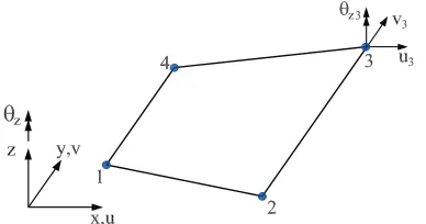
[image:4.504.157.351.368.470.2]The 4-node membrane element with drilling DOFs (Figure 1) is derived by combin-ing the in-plane displacements uscombin-ing Allman-type interpolation functions (Allman, 1984) and the standard bilinear independent normal (drilling) rotation fields. De-tails of the formulation can be found in the original reference (Ibrahimbegovic, Taylor, and Wilson, 1990) and only a brief review is presented here.
Figure 1: A 4-node quadrilateral element with drilling degrees of freedom
The independent rotation field is interpolated as follows.
θz=
4
∑
i=1
Ni(ξ,η)θzi, (1)
and the in-plane displacement fields are approximated by the Allman-type interpo-lation
u=
u v
=
4
∑
i=1
Ni(ξ,η)
ui
vi
+1
8 8
∑
k=5
Nk(ξ,η)(θz j−θzi)
yi j
xi j
where
xi j= xj−xi, yi j=yj−yi, (3)
Ni(ξ,η) = 14(1+ξiξ)(1+ηiη) i=1,2,3,4 (4) Nk(ξ,η) = 12(1−ξ2)(1+ηkη) k=5,7 (5)
Nk(ξ,η) = 12(1+ξkξ)(1−η2) k=6,8. (6)
and the ordered triplets(k,i,j)are given by(5,1,2),(6,2,3), (7,3,4), (8,4,1)
The linear strain matrix is given by
εεεm=symm∇u=
4
∑
i=1
Bmiui, (7)
whereui = [ui vi θzi]T is the nodal vector and the gradient matrixBmi has the
following form
Bmi =
Ni,x 0 Nxi,x
0 Ni,y Nyi,y
Ni,y Ni,x Nxi,y+Nyi,x
. (8)
in whichNx, Nyare Allman’s incompatible shape functions defined as
Nxi =
1
8(yi jNl−yikNm), (9)
Nyi =
1
8(xi jNl−xikNm). (10)
The above indices i, j, k, l, m can be expressed in a Matlab-like definition as follows.
i = 1,2,3,4;m=i+4; l=m−1+4∗f loor(1/i);
k = mod(m,4) +1; j=l−4. (11)
where f loor(x) rounds the elements of x to the nearest integers towards minus infinity andmod(x,y)is the modulus after division ofxbyy.
Furthermore, the skew-symmetric part of the strain tensor (εεεsk) can be expressed as
εεεsk=skew∇u=
4
∑
i=1
where
bi =
−1 2Ni,y 1 2Ni,x 1
16 −yi jNl,y+yikNm,y+xi jNl,x−xikNm,x
−Ni
, (13)
and the indicesi, j,k,l, mare defined by Equation (11).
The variational formulation suggested by Hughes and Brezzi (1989) is described as
Πγ(u,θz) =
1 2
Z
Ω ε
εεTmDmεεεmdΩ+
1 2γ
Z
Ω
(εεεsk−θz)2dΩ−
Z
Ω
uTfdΩ. (14)
Minimization of Equation (14) results in the element membrane stiffness matrix Kmem, which is the sum of matrixKmand a penalty matrixPγ as follows.
Kmem=Km+Pγ = Z
Ω
BTmDmBmdΩ+γ
Z
Ω
bTbdΩ. (15)
The positive penalty parameterγin Equation (15) is problem dependent. However, the formulation is reported to be insensitive to the value ofγ which is taken as the shear modulus value (γ=G) (Hughes, Brezzi, Masud, and Harari, 1989; Ibrahim-begovic, Taylor, and Wilson, 1990). Many recent numerical studies showed that the smaller value of γ (i.e. value of γ/G between 1/10000 and 1) appeared to give more accurate solutions (Long, Geyer, and Groenwold, 2006; Liu, Riggs, and Tessler, 2000; Pimpinelli, 2004). In this study,γ/G=1/1000 is used.
2.2 Plate-bending part
For the plate bending component of the flat shell element, the Mindlin-Reissner type 4-node plate element is employed (Figure 2).
The displacement fielduis approximated as
u= [w θx θy]T=
4
∑
i=1
Niui, (16)
whereNi is the bilinear shape function as in Equation (4) andui= [wi θxi θyi]is
the nodal displacement vector of the element.
The corresponding approximation of curvature is given by
κ=
θx,x
θy,y
θx,y+θy,x
Figure 2: A 4-node quadrilateral plate bending element
where
Bbi =
0 Ni,x 0
0 0 Ni,y
0 Ni,y Ni,x
. (18)
The shear strain is approximated with independent interpolation schemes in the natural coordinate system as
γx
γy
=J−1
γξ
γη
=J−1Nˆ
γηA
γξB
γηC γξD
, (19)
in which
ˆ N= 1
2
(1−ξ) 0 (1+ξ) 0 0 (1−η) 0 (1+η)
, (20)
Jis the Jacobian matrix and the midside nodes A, B, C, D are shown in Figure 2. ExpressingγηA,γηCandγξB,γξDin terms of the discretized fieldsu, we obtain the shear matrix
¯
Bsi=J−1
Ni,ξ b11i Ni,ξ b12i Ni,ξ Ni,η b21i Ni,η b22i Ni,η
, (21)
where
in whichξi∈ {−1,1,1,−1},ηi∈ {−1,−1,1,1}
and(i,M,L)∈ {(1,B,A);(2,B,C);(3,D,C);(4,D,A)}.
Then through the direct application of variational principles, the element plate-bending stiffness matrix can be obtained as follows.
Kp=Kb+Ks=
Z
Ωe
BTbDbBbdΩ+
Z
Ωe
BTsDsBsdΩ, (23)
whereDs, Dbare material rigidity matrices for bending and shear, respectively.
2.3 Construction of a flat shell element
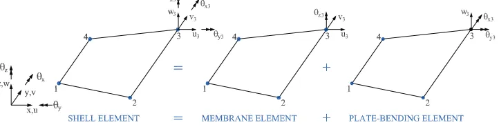
[image:8.504.74.435.309.401.2]The plate bending and membrane formulations presented in the above sections can be combined to form a four-node shell element as shown in Figure 3.
Figure 3: A 4-node quadrilateral flat shell element
When all nodes of the flat shell element are placed in the mid-thickness plane of the shell, the stiffness matrix of a shell element can be formed by combining the plate stiffness and membrane stiffness obtained independently as follows.
Kf lat=
Kmem 0
0 Kp
. (24)
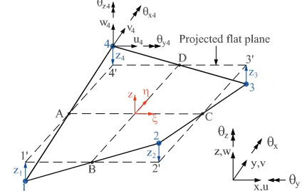
For some shells with double curvature, it may not be possible to have four nodes of the flat shell element on the same plane (warped geometries) and the flat element stiffness must be modified before transformation to the global reference system by using the rigid link correction suggested by Taylor (1987). For the rigid link correction, the mean plane is formed by connecting central points of each side and distances between the mean plane and each nodes are taken to be the same
is employed to transform the nodal variables to the projected flat element variables
q0i=
u0i v0i w0i θxi0
θyi0
θzi0
=
1 0 0 0 0 0
0 1 0 0 0 0
0 0 1 0 0 0
0 zi 0 1 0 0
−zi 0 0 0 1 0
0 0 0 0 0 1
ui vi wi θxi θyi θzi
=Wiqi, (25)
whereWis the projection matrix andzi defines the warpage offset at each nodei
[image:9.504.142.354.293.427.2]perpendicular to the flat mean plane as shown in Figure 4.
Figure 4: The projection of a warped shell element into a flat mean plane
The local element stiffness matrix, considering the warping effects, is obtained as follows
Klocal=WKf latWT. (26)
Then the element stiffness in the global reference systemKglobal is obtained via the
rotation matrixR
3 Strain smoothing approach for flat shell finite element
3.1 Smoothed membrane strain approximation
The membrane strains at an arbitrary pointxCcan be obtained by using the
follow-ing strain smoothfollow-ing operation
˜
εεεm(xC) =
Z
ΩC
ε
εεm(x)Φ(x−xC)dΩ, (28)
whereεεεm is the membrane strain obtained from displacement compatibility
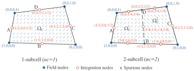
con-dition as given in Equation (7); ΩC is the smoothing cell domain on which the smoothing operation is performed (ΩC may be an entire element or part of an
el-ement as shown in Figure 5, depending on the stability analysis (Liu, Dai, and Nguyen, 2007));Φis a given smoothing function that satisfies at least unity prop-erty R
ΩC
ΦdΩ=1 and, in the present work is defined as
Φ(x−xC) =
1/AC x∈ΩC,
0 x∈/ΩC, (29)
in whichAC=
R
ΩC
[image:10.504.87.416.397.517.2]dΩis the area of a smoothing cell (subcell).
Figure 5: Subdivision of an element intoncsmoothing cells and values of bilinear shape functions at nodes
Substituting Φ into Equation (28) and applying the divergence theorem, one can
get the smoothed membrane strain
˜ ε
εεm(xC) =
1 2AC
Z
ΩC
∂ui
∂xj
+∂uj
∂xi
dΩ= 1
2AC
Z
ΓC
whereΓCis the boundary of the smoothing cell.
Introducing the finite element approximation ofum= [u v θz]T into Equation (30)
gives
˜
εεεm(xC) =B˜m(xC)um, (31)
where
umi = [ui vi θzi]T, (32)
˜
Bmi(xC) =
1 AC Z ΓC
Ninx 0 Nxinx
0 Niny Nyiny
Niny Ninx Nxiny+Nyinx
dΓ. (33)
Applying Gauss integration along 4 segments of the boundaryΓCof the smoothing
domainΩC, the above equation can be rewritten in algebraic form as
˜
Bmi(xC) =
1 AC
4
∑
b=1
nG ∑
n=1
wnNi(xbn)nx 0 0
0
nG ∑
n=1
wnNi(xbn)ny 0
nG ∑
n=1
wnNi(xbn)ny nG
∑
n=1
wnNi(xbn)nx 0
+ 1 AC 4
∑
b=1
0 0 nG ∑
n=1
wnNxi(xbn)nx
0 0
nG ∑
n=1
wnNyi(xbn)ny
0 0
nG ∑
n=1
wnNxi(xbn)ny+ nG
∑
n=1
wnNyi(xbn)nx
(34)
wherenG is the number of Gauss integration points, xbn the Gauss point andwn
the corresponding weighting coefficients. The first term in Equation (34), which relates to the in-plane translations (approximated by bilinear shape functions), is evaluated by one Gauss point (nG=1). The second term, associated with the in-plane rotations (approximated by quadratic shape functions), is computed using two Gauss points (nG=2).
The smoothed membrane element stiffness matrix can be obtained as
˜
Kmem=K˜m+Pγ = R
ΩB˜
T
mDmB˜mdΩ+γ
R Ωb Tbd Ω = nc ∑
C=1
˜ BT
mCDmB˜mCAC+γ
R
Ωb
Tbd
in whichncis the number of smoothing cells. To avoid numerically over-stiffening the membrane, one smoothing cell (nc=1) is used in the present formulation. Higher numbers of smoothing cells will lead to stiffer solutions and the accuracy may not be enhanced considerably. The penalty matrixPγ is integrated using a 1–
point Gauss quadrature to suppress a spurious, zero-energy mode associated with the drilling DOFs.
3.2 Smoothed plate-bending strain approximation
In a similar way, by using the same constant smoothing functionΦas for membrane
strain, the smoothed curvature matrix can be obtained as
˜ κ κκ(xC) =
Z
ΩC
κ
κκ(x)Φ(x−xC)dΩ= 1
2AC
Z
ΓC
(θinj+θjni)dΓ. (36)
Then the relationship between the smoothed curvature field and the nodal displace-ment is written as
˜
κκκ(xC) =B˜b(xC)ub, (37)
where
ubi = [wi θxi θyi]T, (38)
˜
Bbi(xC) =
1 AC Z ΓC
0 Ninx 0
0 0 Niny
0 Niny Ninx
dΓ. (39)
Using integration with one-point Gauss quadrature to evaluate the above equation over four boundary segment of the smoothing cell we obtain
˜
Bbi(xC) =
1 AC
4
∑
b=1
0 Ni(xGb)nx 0
0 0 Ni(xGb)ny
0 Ni(xGb)ny Ni(xGb)nx
lbC. (40)
Finally, the plate-bending element stiffness matrix in Equation (23) can be trans-formed as follows
˜
Kp=K˜b+Ks= nc
∑
C=1
˜
BTbDbB˜bAC+
Z
Ωe
BTsDsBsdΩ. (41)
In Equation (41), the shear termKs is still computed by 2×2 Gauss quadrature
each segment of the smoothing cells of the element. In this study, two smoothing cells (nc=2) as shown in Figure 5 are used for calculating the smoothed bending stiffness matrix of the element in order to ensure the rank sufficiency.
The flat shell element stiffness matrix in Equation (24) is then rewritten as
˜
Kf lat=
˜
Kmem 0
0 K˜p
. (42)
This forms the basis of a new four-node quadrilateral element named MISQ24 (Mixed Interpolation Smoothing Quadrilateral element with 24 DOFs) for analysis of shell structures.
4 Numerical results and discussions
In this section, several benchmark problems are presented to validate and demon-strate the performance of the MISQ24 flat element in shell structural analysis. The developed element performance is compared with that of a fairly complete set of other four-node shell elements in the literature. The list of shell elements used for comparison with the proposed element is outlined in Table 1.
4.1 Scordelis-lo (Barrel vault) roof
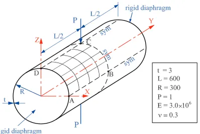
[image:13.504.132.372.476.608.2]The Scordelis-Lo roof provides one of the standard tests to assess the performance of shell elements in a combined bending-membrane problem with the membrane action being dominant. The roof is modelled as a short cylinder shell, loaded by self-weight and supported by rigid diaphragms at the curved edges while the straight edges are free. Geometric, material data and boundary conditions of the problem are shown in the Figure 6.
Table 1: List of shell elements used for comparison in the present study.
Name Brief description
DKQ-4 4-node discrete Kirchoff quadrilateral element of Taylor (1987) SRI-4 bilinear degenerated shell element, with selective reduced integration
of Hughes and Liu (1981)
RSDS-4 bilinear resultant-stress degenerated-shell element, with uniform re-duced integration and stability (Liu, Law, Lam, and Belytschko, 1986) URI-4 4-node uniformly reduced integrated element (Belytschko, Wong, and
Stolarski, 1989)
QPH quadrilateral shell element with physical hourglass control of Be-lytschko and Leviathan (1994)
IBRA-4 4-node shell element with drilling DOFs developed by Ibrahimbegovic and Frey (1994)
MITC4 4-node fully integrated shell element based on assumed shear strain field of Dvorkin and Bathe (1984)
Mixed bilinear element with mixed formulation for membrane and bending stress and full 2x2 quadrature of Simo, Fox, and Rifai (1989)
MIN4T 4-node flat shell with drilling DOFs via explicit Kirchhoff constrains (Liu, Riggs, and Tessler, 2000)
NMS-4F defect-free 4-node flat shell element with drilling DOF (Choi and Lee, 1999)
XSHELL41/42 4-node quasi-conforming flat shell element with driling DOFs (Kim, Lomboy, and Voyiadjis, 2003)
QC5D-SA 4-node flat shell with drilling DOFs and 5-point quadrature by Groen-wold and Slander (1995)
SHELL63 4-node thin shell element with drilling DOFs in ANSYS (1998) T029 4-node Mindlin shell element in Samtech (2003)
Sauer 4-node element proposed by Sauer (1998)
GruWag 4-node element proposed by Gruttmann and Wagner (2005)
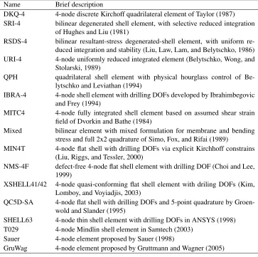
According to MacNeal and Harder (1985), the theoretical value for the vertical de-flection at the center of the free edge is 0.3086, but a slightly lower value 0.3024 seems to have become the reference solution for many publications. In this study the latter value is used to normalize numerical results. Taking advantage of sym-metry, only a quadrant of the roof is discretized and analyzed. Two typical types of mesh, namelyN×Nuniform elements andN×Ndistorted elements are shown in Figure 7.
0 5
10
15 0 5 10
15 20
25 −5
−4 −3 −2 −1 0
0 5
10
15 0 5 10
15 20
25
−5
−4
−3
−2
−1 0
[image:15.504.120.398.96.208.2](a) (b)
Figure 7: The Scordelis-Lo roof: (a) typical regular mesh and (b) irregular mesh.
elements perform quite well in both types of mesh in comparison with the reference solution and other shell elements. The convergence of stress resultants obtained by uniform elements is also presented in Table 3.
Table 2: The Scordelis-Lo roof: displacements at point B, normalized by 0.3024
Model Mesh
4×4 8×8 12×12 16×16 MISQ24 (regular mesh) 1.1912 1.0420 1.0154 1.0063 MISQ24 (irregular mesh) 1.1925 1.0422 1.0155 1.0066
SRI-4 0.964 0.984 – 0.999
RSDS-4 1.201 1.046 – 1.010
T029 (SAMCEF) 0.976 0.986 – 0.993
NMS-4F 1.047 1.005 – 0.997
QPH 0.940 0.980 – 1.010
DKQ-4 1.048 1.005 – 0.996
IBRA-4 1.047 1.005 – 0.997
URI-4 1.219 1.054 – 1.017
[image:15.504.81.424.326.531.2]Table 3: The Scordelis-Lo roof: Stress resultants (bending and membrane compo-nents)
Mesh MxC NxC NyB
4×4 -2.162E3 -3.210E3 6.810E4
8×8 -2.081E3 -3.379E3 7.372E4
16×16 -2.062E3 -3.400E3 7.372E4
quite satisfactory.
1.4 1.6 1.8 2 2.2 2.4 2.6 2.8 −3
−2.5 −2 −1.5 −1
log10(number of nodes)
log
10
(relative error of w
B
) SRI−4
RSDS−4 IBRA−4 T029 NMS−4F QPH DKQ−4 URI−4 MISQ24−re MISQ24−ir
Figure 8: The Scordelis-Lo roof: Convergence behaviour
4.2 A pinched cylinder with end diaphragms
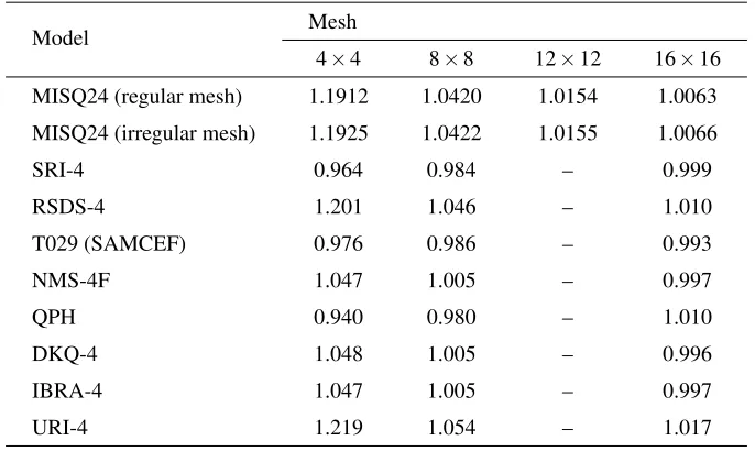
In this section, a pinched cylinder with end diaphragms is considered. This problem is regarded as one of the most severe tests for the performance of the element with the presence of both in-extensible bending and complex membrane states of stress. The cylinder is supported by rigid diaphragms at both ends and pinched with two opposite radial concentrated loads at the middle of the length. The geometrical and material properties of the cylinder are depicted in Figure 9.
[image:16.504.146.350.256.424.2]Figure 9: A pinched cylinder with end diaphragms: Geometry and material data
0 100
200
300 0 50 100 150 200 250
300 0
50 100 150 200 250 300
0 100
200
300 0 50 100 150 200 250
300 0
50 100 150 200 250 300
(a) (b)
Figure 10: A pinched cylinder with end diaphragms: (a) typical regular mesh and (b) irregular mesh.
The theoretical solution of the radial deflection at the loading point (point C) given by Ted Belytschko and Leviathan (1994) is 1.8248×10⁻⁵. The present numerical results with meshes of 4×4, 8×8, 12×12 and 16×16 elements are compared versus other solutions from the literature using 4–node quadrilateral elements. All the numerical results, normalized with respect to the analytical value, are given in the Table 4. It is observed that the performance of the present element is in excellent agreement with the analytic solution for both types of mesh and are better than other shell elements considered in this study. The convergence of stress resultants at the loaded point obtained by uniform elements is also reported in Table 5.
[image:17.504.129.384.271.372.2]Table 4: A pinched cylinder with end diaphragms: displacements at point C, nor-malized by: 1.8248×10⁻⁵
Model Mesh
4×4 8×8 12×12 16×16 MISQ24 (regular) 0.6416 0.9411 0.9921 1.0018 MISQ24 (irregular) 0.6478 0.9375 0.9915 1.0010
MIN4T 0.5040 0.8374 – 0.9619
XSHELL41 0.625 0.926 – 0.995
XSHELL42 0.625 0.918 – 0.992
SRI-4 0.373 0.747 – 0.935
RSDS-4 0.469 0.791 – 0.946
SHELL63(ANSYS) 0.6302 0.9371 – 1.0029
QC5D-SA 0.3759 0.7464 – 0.9300
QPH 0.370 0.740 – 0.930
IBRA-4 0.3704 0.7367 – 0.9343
DKQ-4 0.6357 0.9459 – 1.0160
MITC4 0.3699 0.7398 – 0.9300
[image:18.504.155.348.345.411.2]Mixed 0.3989 0.7628 – 0.9349
Table 5: A pinched cylinder with end diaphragms: Stress resultants.
Mesh MxC NCx
8×8 1.381E-1 -6.501E-2 12×12 2.060E-1 -7.276E-2 16×16 2.464E-1 -7.362E-2
elements using uniform elements. The MISQ24’s convergence rate is even slightly better than the SHELL63 element used in the commercial finite element software ANSYS for this problem.
4.3 A pinched hemispherical shell with an180hole
Figure 12 shows the hemispherical shell with an 180hole subjected to concentrated diametrical loads of opposite signs every 900in the equatorial plane. This problem is a very useful example to check the ability of the element to handle rigid body rotation about the normal to the shell surface and the inextensible bending modes. Shell elements with membrane locking cannot correctly solve this problem. Taking advantage of symmetry, a quadrant of the shell is modelled with uniform elements.
1.4 1.6 1.8 2 2.2 2.4 2.6 2.8 −3
−2.5 −2 −1.5 −1 −0.5 0
log
10(number of nodes)
log
10
(relative error of w
C
)
[image:19.504.135.357.101.275.2]MIN4T SRI−4 XSHELL41 XSHELL42 IBRA−4 RSDS−4 SHELL63 QC5D−SA QPH DKQ−4 MITC4 Mixed MISQ24−re MISQ24−ir
Figure 11: A pinched cylinder with end diaphragms: Convergence behaviour
Figure 12: A pinched hemispherical shell with 180 hole: Geometry and material data
[image:19.504.145.363.337.440.2]1.4 1.6 1.8 2 2.2 2.4 2.6 2.8 −3
−2.5 −2 −1.5 −1 −0.5 0
log
10(number of nodes)
log
10
(relative error of u
A
) MIN4TIBRA−4
[image:20.504.153.342.100.250.2]XSHELL41 XSHELL42 QC5D−SA NMS−4F T029 DKQ−4 Mixed MISQ24
Figure 13: A pinched hemispherical shell with an 180hole:Convergence behaviour
4.4 A hypar shell
A hyperbolic paraboloid shell or hypar shell (Figure 14) as proposed in Gruttmann and Wagner (2005) is studied. This problem is used to assess the performance of element in dealing with warped geometry and the effect of membrane locking. The geometry of the hypar shell is defined by the expressionz= 8xyL. The shell is subjected to a uniform loadpzin the vertical direction with the following boundary
conditions:
[image:20.504.123.376.409.562.2]w(−L/2,y) =w(L/2,y) =w(x,−L/2) =w(x,L/2) =0; uA=uB=0; vC=vD=0.
Figure 14: A hypa shell: Geometry and material data
mod-Table 6: A hemispherical shell with an 180hole: displacements at point A, normal-ized by 0.0940
Model Mesh
4×4 8×8 12×12 16×16 MISQ24 (regular) 0.7670 0.9798 0.9954 0.9960
MIN4T 0.136 0.651 0.897 –
IBRA-4 0.999 0.991 0.990
XSHELL41 1.027 1.001 – 0.990
XSHELL42 0.266 0.652 – 0.960
QC5D-SA 0.386 0.951 – 0.991
DKQ-4 0.897 0.999 – 0.995
NMS-4F 0.935 0.989 – 0.991
Mixed 0.993 0.987 – 0.988
[image:21.504.98.407.121.280.2]els. The analytic solution for the central deflection (w0=4.6) calculated by (Dud-deck, 1962) is used for normalization. Numerical results indicate that the behaviour of the present element is in a close agreement with other reference solutions. It is observed that the present element does not show any sign of membrane lock-ing even with coarse meshes. The element demonstrates an excellent performance where the displacement prediction error for the coarse mesh of 8×8 elements is about 0.35%.
Table 7: A hypar shell: central deflectionw0for different elements, normalized by 4.6
Model Mesh
4×4 8×8 16×16 32×32 64×64
MISQ24 0.978 0.994 0.998 0.999 1.000
DKQ-4 0.980 0.989 0.991 – 0.993
Sauer 0.980 0.991 0.996 – 1.000
GruWag 0.983 0.991 0.996 – 1.000
[image:21.504.116.391.462.546.2]0 500 1000 1500 2000 2500 3000 3500 4000 4500 0.975
0.98 0.985 0.99 0.995 1 1.005
Number of nodes
Normalized centre deflection
[image:22.504.151.342.99.243.2]Taylor Sauer Wagner MISQ24 Analytic
Figure 15: A hypar shell: normalized central deflections with mesh refinement
Figure 16: A partly clamped hypar shell: Geometry and material data
4.5 A partly clamped hyperbolic paraboloid shell
The problem considered in this section is that of a hyperbolic paraboloid shell, clamped along one side and free on three edges and loaded by self-weight (Fig-ure 16). This is a p(Fig-ure bending dominated problem and known to be a very hard test for locking behaviour as suggested in References (Chapelle and Bathe, 1998; Bathe, Iosilevich, and Chapelle, 2000). The shell geometry is described by the equation:z=x2−y2;(x,y)∈
−L
2;
L
2
[image:22.504.147.357.290.388.2]
element. The computed results are reported in Table 8 and Table 9 for displace-ments and strain energies, respectively.
Table 8: A partly clamped hypar shell: deflection at point A with mesh refinement.
Mesh t/L=1/100 t/L=1/1000
MISQ24 MITC16 MISQ24 MITC16
8×4 9.9088E-5 – 7.1209E-3 –
16×8 9.4681E-5 – 6.7129E-3 –
32×16 9.3665E-5 – 6.4677E-3 –
48×24 9.3501E-5 9.3355E-5 6.4264E-3 6.3941E-3
[image:23.504.118.391.331.431.2]64×32 9.3453E-5 – 6.4130E-3 –
Table 9: A partly clamped hypar shell: strain energy with mesh refinement
Mesh t/L=1/100 t/L=1/1000
MISQ24 MITC16 MISQ24 MITC16
8×4 1.8028E-3 – 1.2512E-2 –
16×8 1.7073E-3 – 1.1633E-2 –
32×16 1.6858E-3 – 1.1155E-2 –
48×24 1.6822E-3 1.6790E-3 1.1077E-2 1.1013E-2
64×32 1.6812E-3 – 1.1055E-2 –
Figure 17 demonstrate the convergence of displacement and strain energy. It can be seen that the proposed element MISQ24 performs well, exhibiting insensitivity to the decrease in thickness.
4.6 A pre-twisted cantilever beam
0 500 1000 1500 2000 2500 3000 3500 4000 4500 1
1.02 1.04 1.06 1.08 1.1 1.12 1.14
Number of nodes
Normalized deflection at point A
t/L=1/100 t/L=1/1000 MITC16 Solution
(a)
0 500 1000 1500 2000 2500 3000 3500 4000 4500
1 1.05 1.1 1.15
Number of nodes
Normalized strain energy
t/L=1/100 t/L=1/1000 MITC16 Solution
[image:24.504.154.344.96.429.2](b)
Figure 17: A partly clamped hypar shell: (a) Convergence of the deflection at point A and (b) convergence of the strain energy.
Table 10 presents the obtained results with mesh refinement together with other numerical solutions in the literature. It is observed that the MISQ24 element has no difficulties in dealing with warped geometries. Its performance is found to be better than that of some other elements cited here such as XSHELL42, RSDS-4 and MITC4 elements.
5 Conclusions
analy-Figure 18: Pre-twisted cantilever beams: geometry and material data.
Table 10: Isotropic pre-twisted cantilever beam: tip displacements, normalized by 5.424×10⁻²for in-plane displacements and by 1.754×10⁻²for out-of-plane displacements.
Load case Model Mesh
2×6 4×12 4×24
In-plane MISQ24 0.979 1.006 1.008
DKQ-4 – – 0.996
XSHELL41 – – 0.997
XSHELL42 – – 1.228
RSDS-4 – – 1.411
MITC4 – – 0.996
Out-of plane MISQ24 0.811 0.928 1.015
DKQ-4 – – 0.998
XSHELL41 – – 0.999
XSHELL42 – – 1.473
RSDS-4 – – 1.361
MITC4 – – 0.974
[image:25.504.103.399.238.451.2]avoid membrane locking due to drilling DOFs.
Several numerical benchmark investigations are carried out to validate and demon-strate the efficiency and accuracy of the proposed element. The new flat shell el-ement provides very excellent results to most of problems when compared with analytic solutions and referenced four-node shell elements in the literature. It is observed that the element is free of membrane and shear locking and could be a good candidate for general shell structural analysis in engineering practice where the range of thickness-to-length (t/L) ratio is usually from 1/10 to 1/1000.
Acknowledgement: The supports from the Faculty of Engineering and Survey-ing (FoES) and the Computational EngineerSurvey-ing & Science Research Center (CESRC), USQ, Australia, are gratefully acknowledged. The authors would like to thank the referees for their helpful comments.
References
Allman, D. J.(1984): A compatible triangular element including vertex rotations for plane elasticity analysis. Computers and Structures, vol. 19, pp. 1–8.
Andelfinger, U.; Ramm, E.(1993): EAS-elements for two-dimensional, three-dimensional, plate and shell structures and their equivalence to HR-elements. In-ternational Journal for Numerical Methods in Engineering, vol. 36, pp. 1311– 1337.
ANSYS(1998): ANSYS User’s Manual v5.5, 1998.
Atluri, S. N.(1980): On some new general and complementary energy theorems for the rate problems in finite strain, classical elastoplasticity. Journal of Structural Mechanics, vol. 8, no. 1, pp. 61–92.
Atluri, S. N. (1984): Alternate stress and conjugate strain measures and mixed variational formulations involving rigid rotations, for computational analyses of finitely deformed plates and shells: Part-i: Theory. Computers & Structures, vol. 18, no. 1, pp. 93–116.
Atluri, S. N.; Cazzani, A.(1994): Rotations in computational solid mechanics. In Archives for Computational Methods in Engineering, ICNME, volume 2, pp. 49–138.
Bathe, K. J.; Iosilevich, A.; Chapelle, D.(2000): An evaluation of the MITC shell elements. Computers and Structures, vol. 75, pp. 1–30.
Belytschko, T.; Leviathan, I.(1994): Physical stabilization of the 4-node shell with one-point quadrature. Computer Methods in Applied Mechanics and Engi-neering, vol. 113, pp. 321–350.
Belytschko, T.; Lin, J. I.; Tsay, C.-S.(1984): Explicit algorithms for the nonlin-ear dynamics of shells. Computer Methods in Applied Mechanics and Engineering, vol. 42, pp. 225–251.
Belytschko, T.; Tsay, C.-S.(1983): A stabilization procedure for the quadrilateral plate element with one-point quadrature. International Journal for Numerical Methods in Engineering, vol. 19, pp. 405–419.
Belytschko, T.; Wong, B. L.; Stolarski, H.(1989): Assumed strain stabiliza-tion procedure for the 9-node Lagrange shell element. International Journal for Numerical Methods in Engineering, vol. 28, pp. 385–414.
Bischoff, M.; Bletzinger, K.(2001): Stabilized DSG plate and shell elements. In Trends in Computational Structural Mechanics, CIMNE, Barcelona, pp. 253–263.
Bischoff, M.; Ramm, E. (1997): Shear Deformable shell elements for large strains and rotations. International Journal for Numerical Methods in Engineering, vol. 40, pp. 4427–4449.
Cardoso, R. P. R.; Yoon, J. W.; Valente, R. A. F. (2006): A new approach to reduce membrane and transverse shear locking for one-point quadrature shell elements: linear formulation. International Journal for Numerical Methods in Engineering, vol. 66, no. 2, pp. 214–249.
Cardoso, R. P. R.; Yoon, J. W.; Valente, R. A. F. (2007): Enhanced one-point quadrature shell element for nonlinear applications. International Journal for Numerical Methods in Engineering, vol. 69, pp. 627–663.
Chapelle, D.; Bathe, K. J. (1998): Fundamental considerations for the finite element analysisof shell structures. Computers and Structures, vol. 66, pp. 19–36.
Chen, J.; Wu, C.; You, Y. (2001): A stabilized conforming nodal integration for Galerkin meshfree method. International Journal for Numerical Methods in Engineering, vol. 50, pp. 435–466.
Choi, C.-K.; Lee, T.-Y. (2003): Efficient remedy for membrane locking of 4-node flat shell elements by non-conforming modes. Computer Methods in Applied Mechanics and Engineering, vol. 192, pp. 1961–1971.
Cook, R. D.(1994): Four-node ’flat’ shell element: drilling degrees of freedom, membrane-bending coupling, warped geometry and behaviour. Computers and Structures, vol. 50, pp. 549–555.
Cui, X. Y.; Liu, G. R.; Li, G. Y.; Zhao, X.; Nguyen, T. T.; Sun, G. Y.(2008): A smoothed finite element method (sfem) for linear and geometrically nonlinear anal-ysis of plates and shells. CMES: Computer Modeling in Engineering & Sciences, vol. 28, no. 2, pp. 109–125.
Duddeck, H. (1962): Die Biegetheorie der flachen hyperbolischen Paraboloid-schale z=cxy¯ . Archive of Applied Mechanics (Ingenieur Archiv), vol. 31, pp. 44–78.
Dvorkin, E. N.; Bathe, K. J.(1984): A continuum mechanics based four node shell element for general nonlinear analysis. Engineering Computations, vol. 1, pp. 77–88.
Eckstein, A.; Basar, Y.(2000): Ductile damage analysis of elasto-plastic shells at large inelastic strains. International Journal for Numerical Methods in Engineer-ing, vol. 47, pp. 1663–1687.
Groenwold, A. A.; Slander, N.(1995): An efficient 4-node 24 DOF thick shell finite element with 5-point quadrature. Engineering Computations, vol. 12, pp. 723–747.
Gruttmann, F.; Wagner, W.(2005): A linear quadrilateral shell element with fast stiffness computation. Computer Methods in Applied Mechanics and Engineering, vol. 194, pp. 4279–4300.
Hughes, T. J. R.; Brezzi, F.(1989): On drilling degrees of freedom. Computer Methods in Applied Mechanics and Engineering, vol. 72, pp. 105–121.
Hughes, T. J. R.; Brezzi, F.; Masud, A.; Harari, I.(1989): Finite element with drilling degrees of freedom: Theory and numerical evaluations. In Proceedings of the fifth international symposium on numerical methods in engineering, pp. 3–17. Computational mechanics publications, Ashurst, U.K.
Hughes, T. J. R.; Liu, W. K.(1981): Nonlinear finite element analysis of shells: Part II. Two-dimensional shells. Computer Methods in Applied Mechanics and Engineering, vol. 27, pp. 167–182.
Ibrahimbegovic, A.; Frey, F. (1994): Stress resultant geometrically non-linear shell theory with drilling rotations. Part III: Linearized kinematics. International Journal for Numerical Methods in Engineering, vol. 37, pp. 3659–3683.
Ibrahimbegovic, A.; Taylor, R. L.; Wilson, E. L.(1990): A robust quadrilateral membrane finite element with drilling degrees of freedom. International Journal for Numerical Methods in Engineering, vol. 30, pp. 445–457.
Iura, M.; Atluri, S. N.(1992): Formulation of a membrane finite element with drilling degrees of freedom. Computational Mechanics, vol. 96, pp. 417–428.
Kim, K. D.; Lomboy, G. R.; Voyiadjis, G. Z.(2003): A 4-node assumed strain quasi-conforming shell element with 6 degrees of freedom. International Journal for Numerical Methods in Engineering, vol. 58, pp. 2177–2200.
Koschnick, F.; Bischoff, M.; Camprubi, N.; Bletzinger, K. (2005): The dis-crete strain gap method and membrane locking. Computer Methods in Applied Mechanics and Engineering, vol. 194, pp. 2444–2463.
Lee, P.-S.; Bathe, K.-J.(2004): Development of MITC isotropic triangular shell finite elements. Computers & Structures, vol. 82, no. 11-12, pp. 945–962.
Lee, S.; Pian, T.(1978): Improvement of plate and shell finite elements by mixed formulations. AIAA Journal, vol. 16, pp. 29–34.
Liu, G. R.; Dai, K. Y.; Nguyen, T. T.(2007): A smoothed finite element method for mechanics problems. Computational Mechanics, vol. 39, no. 6, pp. 859–877.
Liu, J.; Riggs, H. R.; Tessler, A.(2000): A four-node, shear-deformable shell element developed via explicit Kirchhoff constraints. International Journal for Numerical Methods in Engineering, vol. 49, pp. 1065–1086.
Liu, K. K.; Law, E. S.; Lam, D.; Belytschko, T. (1986): Resultant-stress degenerated-shell element. Computer Methods in Applied Mechanics and En-gineering, vol. 55, pp. 259–300.
MacNeal, R. H. (1978): A simple quadrilateral shell element. Computer and Structures, vol. 8, pp. 175–183.
MacNeal, R. H.(1982): Derivation of element stiffness matrices by assumed stain distribution. Nuclear Engineering Design, vol. 70, pp. 3–12.
MacNeal, R. H.; Harder, R. L.(1985): A proposed standard test problems to test finite element accuracy. Finite Element in Analysis and Design, vol. 1, pp. 3–20.
Nguyen-Van, H.; Mai-Duy, N.; Tran-Cong, T.(2007): A simple and accurate four-node quadrilateral element using stabilized nodal integration for laminated plates. CMC: Computers, Materials&Continua, vol. 6, no. 3, pp. 159–176.
Nguyen-Van, H.; Mai-Duy, N.; Tran-Cong, T.(2008a): A node-based element for analysis of planar piezoelectric structures. CMES: Computer Modeling in En-gineering&Sciences, vol. 36, no. 1, pp. 65–96.
Nguyen-Van, H.; Mai-Duy, N.; Tran-Cong, T.(2008b): A smoothed four-node piezoelectric element for analysis of two-dimensional smart structures. CMES: Computer Modeling in Engineering&Sciences, vol. 23, no. 3, pp. 209–222.
Noor, A. K.; Peters, J. M.(1981): Mixed models and reduced/selective integra-tion displacement models for nonlinear analysis of curved beams. International Journal for Numerical Methods in Engineering, vol. 17, pp. 615–631.
Pimpinelli, G. (2004): An assumed strain quadrilateral element with drilling degrees of freedom. Finite Element in Analysis and Design, vol. 41, pp. 267–283.
Samtech(2003): Samcef User’s Manual v10.1, 2003.
Sauer, R. (1998): Eine einheitliche Finite Element Formulierung fur Stabund Schalentragwerke mit endlichen Rotationen. Bericht 4. Institut fur Baustatik, Uni-versitat Karlsruhe (TH).
Simo, J. C.; Fox, F. D.; Rifai, M. S.(1989): On a stress resultant geometrically exact shell model. Part II: The linear theory; Computational aspects. International Journal for Numerical Methods in Engineering, vol. 73, pp. 53–92.
Simo, J. C.; Rifai, M. S.(1990): A class of mixed assumed strain methods and the method of incompatible models. International Journal for Numerical Methods in Engineering, vol. 29, pp. 1595–1638.
Suetake, Y.; Iura, M.; Atluri, S. N.(2003): Variational formulation and symmet-ric tangent operator for shells with finite rotation field. CMES: Computer Modeling in Engineering&Sciences, vol. 4, no. 2, pp. 329–336.
Taylor, R. L.(1987): Finite element analysis of linear shell problems. In White-man, J.(Ed): Proceeding of the Mathematics in Finite Element and Applications. Academic Press, New York.
Yang, H. T. Y.; Saigal, S.; Masud, A.; Kapania, R. K.(2000): A survey of recent shell element. International Journal for Numerical Methods in Engineering, vol. 47, no. 1-3, pp. 101–127.