Evaluation of a new approach for modelling the screw-bone
interface in a locking plate fixation – a corroboration study
Mehran Moazen1, Jonathan H Mak1, Alison C Jones1, Zhongmin Jin1,2, Ruth K Wilcox1, Eleftherios Tsiridis3-5
1Institute of Medical and Biological Engineering, University of Leeds, Leeds, LS2
9JT, UK
2Institute of Advanced Manufacturing Technology, School of Mechanical
Engineering, Xi’an Jiaotong University, Xi’an, 710049, P.R. of China
3Academic Department of Orthopaedic and Trauma, University of Leeds, Leeds,
LS2 9JT, UK4Department of Surgery and Cancer, Division of Surgery, Imperial
College London, London, W12 0HS UK
5Academic Orthopaedics and Trauma Unit, Aristotle University Medical School,
University Campus 54 124, Thessaloniki, Greece
Corresponding author:
Mehran Moazen, PhD
Institute of Medical and Biological Engineering, School of Mechanical Engineering, University of Leeds, Woodhouse Lane, Leeds, LS2 9JT
Tel: +44 (0) 113 34 32160; Fax: +44 (0) 113 24 24611; Email: [email protected]; [email protected] Abstract word count: 218
Main text (excluding reference list) word count: 4559 Number of Tables: 3
Abstract
Computational modelling of the screw-bone interface in fracture fixation constructs is challenging. Whilst incorporating screw threads would be a more realistic representation of the physics, this approach can be computationally expensive. Several studies have instead suppressed the threads and modelled the screw shaft with fixed conditions assumed at the screw-bone interface. This study assessed the sensitivity of the computational results to modelling approaches at the screw-bone interface. A new approach for modelling this interface was proposed and it was tested on two locking screw designs, in a diaphyseal bridge plating configuration. Computational models of locking plating and far cortical locking constructs were generated and compared to in vitro models described in prior literature to corroborate the outcomes. The new approach led to closer agreement between the computational and the experimental stiffness data while the fixed approach led to overestimation of the stiffness predictions. Using the new approach, the pattern of load distribution and the magnitude of the axial forces, experienced by each screw, were compared between the locking plating and far cortical locking constructs. The computational models suggested that, under more severe loading conditions, far cortical locking screws might be under higher risk of screw pull-out than the locking screws. The proposed approach for modelling the screw-bone interface can be applied to any fixation involved application of screws.
1. Introduction
Clinical failure of bone fracture fixation constructs is not common but still occurs.1-4
This has generated interest from both the biomechanics and orthopaedic trauma communities to investigate the strength and stability of fracture fixation constructs.3-13
There are several failure mechanisms of these constructs such as: plate failure, screw shaft bending, screw breakage or screw pull-out.1-3Screw pull- out although is
not common but can occur in the case of poor bone quality14, periprosthetic fracture
fixations where the surgical approach is constrained by the presence of a prosthesis and uni-cortical screws may be used, or where non-locking screws are used. Therefore, a number of studies have been carried out to investigate various design features of screws.11,13-16 Experimental pull-out tests on a single screw in cadaveric
or synthetic bones have been widely used to find out the optimum screw design.17-20
Such tests provide invaluable information on the performance of a single screw, however, our understanding of the pattern and magnitude of the load distribution between screws in a fracture fixation construct is still limited.21
computationally expensive to solve due to the high mesh densities required when a number of screws are used. Several authors have instead suppressed the threads and modelled the screw shaft with fixed conditions assumed at the screw-bone (or cylinder-bone) interface25-27, which is referred to here as the “fixed” condition.
However, this approach can lead to an overestimation of the construct stiffness and it is difficult to estimate the magnitude of the pull-out forces that are experienced by each screw in the construct. Understanding the axial screw forces can potentially shed light on rationale behind the clinical screw pull-out cases1-3 and facilitate
advances to overcome these challenges.
Therefore, the aims of this study were to (1) assess the sensitivity of the computational results to modelling approaches at the screw-bone interface; (2) propose and test a new approach for modelling the screw-bone interface and (3) implement the new approach to estimate the pattern of load distribution and the magnitude of the forces that are experienced by each screw, between two locking screw designs, in a diaphyseal bridge plating configuration. It should also be noted that the computational models were developed based on in vitrostudy of Bottlang et al.11 and corroborated against their results in the present study. To ensure
like-for-like comparison between the computational models in this study and the previously reported experimental models,11the authors were contacted and they kindly provided
us with all necessary information for the current study.
2. Materials and Methods
tests were performed (Fig. 2) to understand the effect of modelling the screw-bone interface and associated input parameters on the overall stiffness of this construct. Here, a new approach for modelling the screw-bone interface was proposed. In the second step, FE models of far cortical locking (FCL) constructs were developed based on the parameters that best fitted the experimental data of the LP case. The models were assembled to correspond to the experimental tests of Bottlang et al.11
on synthetic femoral diaphysis bone, and were loaded under same magnitude and loading conditions (i.e. axial compression, torsion and bending).
2.1. Model development
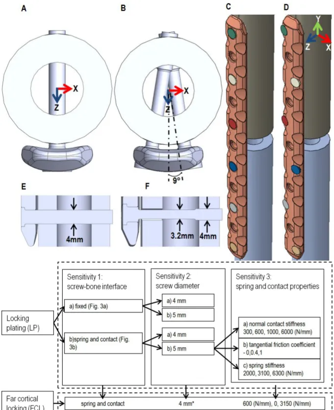
Computer aided design (CAD) models of the locking plate, and the locking and far cortical locking screws were provided by Bottlang et al. as described in Bottlang et al.11 In brief, the plate had eleven holes, a thickness of 4.5 mm, a width of 17.5 mm
and a length of 200 mm. The locking screws had a uniform outer diameter of 4.5 mm and core diameter of 4 mm. The far locking screws had a section with a diameter of 3.2 mm, to avoid any fixation at the near cortex, and a 4.5mm outer diameter at the far cortex (Fig. 1). To assess sensitivity of the FE results to the diameter of the modelled screws, locking screws were modelled with 4 mm and 5 mm diameters (sensitivity 2 in Fig. 2). FCL screws were modelled with a 4 mm diameter (core diameter) at the far cortex. In all cases screw threads were suppressed (Fig. 1).
These implants were used to fix a transverse fracture, with a 10 mm fracture gap, in a cylindrical model replicating a non-osteoporotic femoral diaphysis with an outer diameter of 27 mm and a wall thickness of 7 mm.11 The modelled diaphysis is
Pacific Research Laboratories, Vashon, Washington). For each plating case, screws were placed in the first, third and fifth holes from the fracture site (Fig. 1). The far locking screw fixations were arranged in a staggered 9° angle configuration (Fig. 1). This configuration was used in the experimental study11 to increase the torsional
stiffness of the FCL construct. The two construct fixations were assembled with a 1 mm gap between the plate and bone in SolidWorks (Dassault Systèmes SolidWorks Corp., Concord, MA, USA). These models were then exported to a finite element package (ABAQUS v. 6.9, Simulia Inc., Providence, RI, USA).
2.2. Material properties
All sections were assigned isotropic material properties with an elastic modulus of 16.3 GPa for the synthetic bone28 and 110 GPa for the titanium plate and screws.27
A Poisson’s ratio of 0.3 was used for all materials.27 These properties were chosen
to match the study of Bottlang et al.11
2.3. Interactions
The interface between the screw head and plate was fixed. Penalty based contact conditions were specified at both the plate-bone interface and between the midshaft of the FCL screws and the bone at the near cortex with a coefficient of friction of 0.3729 and normal contact stiffness of 600 N/mm.30 It should be noted that
plate-bone contact was not found to occur under the loading considered in this study.
Both approaches are illustrated in Fig. 3. The latter approach was implemented using spring and contact elements. Here, sliding contact conditions were created between the screw and the bone, while screw pull-out/push-in was resisted by attaching two spring elements between the screw and the bone (as it is shown in Fig. 3), allowing some relative movement at this interface. The spring elements spanned the length of screw where the thread would be embedded into bone, with the far cortex end attached to the screw and the near cortex end attached to the bone. It
should be noted that (1) the spring attachment point on the bone for LP was on the near cortex and for the FCL was on the far cortex; (2) the spring forces were independent of the initial lengths (i.e. F=K × dL where F is force, K is spring stiffness and dL is difference between the spring length before and after loading); (3) any number of spring elements could have been chosen, however since they are effectively attached in parallel to each other, the stiffness of each spring should be equal to the total stiffness divided by the number of springs. This approach required further assumptions in relation to the choice of contact and total spring stiffness parameters. Therefore, further sensitivity tests were performed.
Contact was modelled using a penalty based contact condition with a frictionless coefficient and a normal contact stiffness. The normal contact stiffness was initially set to 600 N/mm based on Bernakiewicz and Viceconti30 who found that this value
for the titanium-bone interface closely replicated the subsidence of a cementless hip stem. This contact stiffness value was then altered to 300 and 1000 N/mm31 for
sensitivity test 3a and the friction coefficient was altered to 0.4 and 1 for sensitivity test 3b to cover the range of experimental data reported in literature32, 33(Fig. 2). As
of Zdero et al.19 This group reported an average ultimate pull-out force and work to
pull-out of 6390 N and 6.5 J respectively for 4.5 mm screws on femoral diaphysis with similar mechanical properties to those used in this study. Based on these values, an elastic screw displacement of 2.034 mm was calculated (i.e. [2×work]/load=displacement - [2×6.5 J]/6390 N=2.034 mm), and based on this displacement, a total stiffness of 3141 N/mm (i.e. load/displacement=stiffness - 6390 N/2.034 mm=3141 N/mm) was calculated for both springs for the initial elastic pull-out of the screw. The total spring stiffness was altered to 2000 and 6300 N/mm for sensitivity test 3c (Fig. 2). Note that any radial pre-stress at the screw-bone interface due to the screw insertion was not considered in this study.
In all cases stiffness values were compared under three loading conditions (as described in 2.4). The baseline values were used for all FCL models, except spring stiffness where the baseline value was halved, as screws are initially in contact with bone at just far cortex.19
2.4. Boundary conditions and loads
construct was loaded to generate constant bending of 10 Nm across the plate. Here the bone was constrained at the support point only along Z direction (see Fig. 1 for X, Y and Z directions). The aforementioned boundary condition were applied to replicate the experimental set ups.
2.5. Mesh sensitivity
Tetrahedral (C3D10M) elements were used to mesh all of the components in a finite element package (ABAQUS v. 6.9, Simulia Inc., Providence, RI, USA). Convergence was tested by increasing the number of elements from 70,000 to 1,600,000 in five steps. The solution converged on the parameter of the interest (≤ 5% - axial stiffness, torsional and bending rigidity as well as spring force) with approximately 400,000 elements. The spring forces converged at an element size of approximately 0.5 mm at the screw-bone interface.
2.6. Simulations and measurements
The models were solved and analysed in ABAQUS. The axial stiffness was calculated by dividing the magnitude of axial load by displacement of the proximal section of the specimens. Torsional stiffness was calculated by dividing the magnitude of torsion by the rotation around the diaphyseal axis. Torsional stiffness was multiplied by the specimen length of 260 mm to derive torsional rigidity. Bending stiffness was expressed in terms of flexural rigidity as EI=Fa2(3l-4a)/12y, where F is
the total applied force, l is the distance between the lower supports (400 mm), a is the distance between the lower and upper supports (55 mm) and y is the displacement of the diaphysis at the applied load.11 Interfragmentary motion was
displacements in the frontal plane between the most distal point of the proximal fragment and the most proximal point of the distal fragment.
3. Results
Increasing the screw diameters by 1 mm (25%) led to an increase in axial stiffness, torsional and bending rigidity of the construct of 32%, 30% and 3% respectively (Table 1 - fixed condition). A similar pattern of stiffness increase was found when increasing the diameter with the alternative screw-bone interface condition (Table 1-spring and contact). Moving from the fixed to the 1-spring and contact interface condition caused a reduction in axial stiffness, torsional and bending rigidity of the construct by 44%, 39% and 28% respectively, based on the 4 mm screw diameter (Table 1).
Sensitivity tests on the input parameters for the spring and contact approach (with screw diameter of 5 mm) showed that increasing the normal contact stiffness, friction coefficient and spring stiffness each led to an increase in the axial stiffness, torsional and bending rigidity of construct (Table 2). Over the range of tested input parameters, axial stiffness and torsional rigidity were most sensitive to the normal contact stiffness (a maximum increase of 50% and 17%) followed by the friction coefficient (maximum increase of 17% and 8%) and spring stiffness (maximum increase of 5% and 0%). Bending rigidity was most sensitive to the friction coefficient followed by spring stiffness and normal contact stiffness (7%, 6% and 6% respectively).
spring and contact approach). The models successfully replicated the experimental bi-linear stiffness in the FCL case, with a predicted initial stiffness of 0.29 kN/mm and secondary stiffness of 2.3 kN/mm (for a load >400 N). The initial stiffness of this construct was 90% lower than LP stiffness (3 kN/mm based on computational model).
Equivalent bi-linear behaviour of the FCL was predicted under torsion, with a rigidity of 0.11 Nm2/deg initially, followed by a secondary rigidity of 0.41 Nm2/deg with a
torsion >1 Nm. Here the FCL initial rigidity was 82% lower than the LP construct (0.6 Nm2/deg). In bending, the computational model did not predict a bi-linear rigidity, yet
it showed 13% reduction in rigidity compared to the LP (61.7 Nm2- see Table 3).
A comparison of interfragmentary motion between the LP and FCL construct types, under 200 N axial load, is shown in Fig. 5. The LP construct showed less than 0.2 mm of movement at both cortices. Although the FCL construct showed more movement than the LP case, it remained less than 1 mm. The near to far cortex interfragmentary motion ratios for the LP and FCL constructs were 0.4 and 0.92 respectively (Fig. 5).
screws failed at the plate bone interface and FLC screws were bent, in both case elevated level of von Mises stress was found in the screws. Under bending bone failure occurred experimentally at either most proximal or most distal screw where also computationally high level of stress was observed.
The spring forces, which represent the forces acting in the direction of the screw shafts, are shown in Fig. 6 for the LP and FCL constructs. Under axial loading of 200 N and 1000 N, the closest screw to the fracture side on the distal fragment (S4 in Fig. 6) experienced the highest spring force. Comparing the LP and FCL construct at this screw, the FCL showed 92% (under 200 N) and 25% (under 1000 N) increase in the total spring forces. Under torsion the spring forces in the FCL construct were considerably higher than in the LP construct. For instance, under torsion of 1 N.m and 10 N.m at the screw number 4 (S4 - see Fig. 6), the total spring forces for the FCL construct compared to the LP construct were over a hundred times (18.17 vs. 0.17 N) and seven times (113.17 vs. 15.21 N) higher respectively.
4. Discussion
Computational models of locking plating (LP) and far cortical locking (FCL) constructs were developed based on in vitro models of Bottlang et al.11
Corroboration with experimental data was undertaken to build confidence in the results of the computational models.34, 35 The general trends of experimental stiffness
Sensitivity tests highlighted that modelling the screw-bone interface with the new proposed approach, and with cylindrical screws that matched the core diameter of the experimental screws, generally led to a closer agreement between the overall stiffness of the computational and experimental models in the LP construct. Therefore, the same conditions were used in modelling the FCL construct. These results also highlighted that “fixed” modelling of the interfaces in computational models underestimated the potential screw-bone micromovements that are present in reality during elastic deformation and therefore led to an overestimation of the overall construct stiffness e.g. by 83% based on screw diameter of 4 mm for axial stiffness (Table 1). Such overestimation can vary depending on the applied loading to the system.
The results of the spring and contact sensitivity tests in the LP construct showed that axial stiffness and torsional rigidity were most sensitive to the normal contact stiffness. In solving the contact problem at each contact pair, overclosure is monitored at nodes and must be corrected at the contact surface. The magnitude of the required push back force is calculated based on the overclosure through a contact stiffness matrix.30 Contact stiffness depends on the shape, size and material
properties of the construct and does not have any physical meaning. Higher values of contact stiffness can lead to an ill-conditioned numerical problem (over constraint issues and a higher number of iterations) while a low contact stiffness produces higher overclosure and contributes some degree of stress inaccuracy.30, 36 This
interface. Under bending, the results were much less sensitive to the contact stiffness and more sensitive to the friction coefficient and spring stiffness (Table 2) which both constrain the longitudinal movement of the screws. This added to the fact that fixed conditions (Table 1) led to closer agreement between the computational and experimental models under bending (86.2 vs. 82.9 Nm2 respectively) suggest
that the screw-bone interface under bending was under high longitudinal force and perhaps minimal radial overclosure.
Since the spring-contact approach generally fitted more closely to the experimental results,11 in the LP construct, it was expected that a close agreement between the
computational and experimental data in the FCL construct should be obtained. Also of interest was whether the new approach was capable of predicting the experimental differences between the two screw designs, in terms of stiffness and interfragmentary motion.
found experimentally for the FCL construct because the screw shaft did not come in contact with the near cortex. In fact, the new approach also underestimated the bending rigidity of the LP construct by 25% (see Table 3). But, it should be noted that the experimental models showed an almost linear stiffness under bending with 15% difference between the initial and secondary stiffness in the FCL construct (59 and 68.1 Nm2respectively). In terms of interfragmentary motion results, while there were
differences (up to 47%) between the computational and experimental results, it was interesting that the near to far cortex interfragmentary motion ratios for the LP and FCL for the computational and experimental models were almost the same (see Fig. 5). The discrepancies between the experimental and computational models results could be due to minor differences in for example: the loading apparatus, material properties or measurement position (in case of interfragmentary motions).
Despite the discrepancy between the computational and experimental models, both models captured the reduction in stiffness of FCL in comparison to the LP construct. Furthermore computational models of both LP and FCL constructs qualitatively predicted high level of stress in the locations where experimental models failed. This provides confidence in the computational models despite the numerical discrepancies with the experimental models. It should be note that since experimental strain measurement did not perform by Bottlang et al.,11 to corroborate
the computational strain prediction, a qualitative contour plot of von Mises stress was presented in Fig X.
occur at the screw-bone interface into the computational models at far less computational cost than modeling the actual screw threads albeit considering that spring stiffnesses are based on experimental pull out data. It also estimates the axial resistive force between the screw and the bone from the spring forces. By predicting the forces that screws are experiencing in fracture fixation constructs, the performance of the screws can be optimized to reduce the risk of pull-out.22 Future
studies need to be undertaken in this respect to find the optimum screw design in the case of poor bone quality14 or periprosthetic fracture fixations where there is higher
risk of screw pull-out and it is likely that the predicted axial screw forces would be increased compared to the current study. In this study, the capability of the presented approach was shown in comparing the screw forces experienced by two different screw designs.
The difference in the total spring forces between the LP and FCL constructs was higher during the initial loading, corresponding to the initial stiffness, than during the secondary loading e.g. 92% vs. 25% for S4 at 200 and 1000N axial load respectively. Also, there was a higher difference between the two springs forces in each screw in the FCL construct compared to the LP construct e.g. 77% vs. 4% for S4 at 200N respectively. Both aforementioned differences are due to the underlying design behind FCL screws that provide far cortical fixation (one cortex fixation) during the initial loading and that (1) progressively stiffen the construct as the screws come into contact with the bone at the near cortex;11 (2) undergo higher bending
that, under more severe loading conditions, FCL screws might be under higher risk of screw pull-out than the locking screws. However, under axial loading of 200 N that corresponds to the toe-touch weight bearing recommended for the immediate postoperative period,37 the maximum spring forces of ca. -24 N and -46 N (note
negative values indicate pull-out) were predicted at screw number 4 (S4) for LP and FCL construct (Fig. 6A). The aforementioned spring forces are considerably lower than the ultimate pull-out force values reported by Zdero et al.19 for a 4.5mm screw
on femoral diaphysis with similar mechanical properties to those used in this study (i.e. 6390 N for bicortical screws). Nevertheless, take must be care in using the spring forces reported here as these are clearly dictated by the spring stiffness values and the boundary condition used in this study. In exact modelling of these input parameters can lead to unrealistic transverse motion at the screw-bone interface. Noteworthy that, estimating screw loosening under cyclic loading based on spring forces predicted in this study would be possible, but it would require further experimental data on cyclic loading of single screw pull-out.
There are a number of limitations in both experimental and computational models considered in this study. Perhaps the most significant are that: (1) an idealized diaphyseal shaft was modelled where rigid distal fixation was assumed and effect of muscle forces was eliminated – these are likely to alter the loading condition applied to the construct, addition of the muscle forces would minimize the bending moments and lead to axial loading of the bone these can potentially increase the predicted stiffness values38 and reduce the predicted spring forces presented in Fig. 6 ;(2) an
yet perfect fracture reduction is challenging; (3) the assigned material properties were those of synthetic bone fixed with a plate and screws made of titanium. A less stiff bone would reduce the overall stiffness values predicted in this study11 and is
likely to increase the chance of screw pull-out. A stiffer plate and screw material, such as stainless steel is likely to increase stiffness predictions and it would perhaps reduce the chance of screw pull-out (considering the unrealistic fracture gap) and mechanical failure; and (4) static loading was considered – where in reality the fracture fixation construct is under cyclic loading and loss of system stiffness and fatigue failure can be an issue. However, perhaps as far as partial load bearing is applied, callus formation can occur39 that will reduce the fixation load bearing, further
Conclusion
This paper described development of a computational model of locking plating and far cortical locking constructs in a diaphyseal bridge plating configuration based on the experimental tests of Bottlang et al.11 Several sensitivity analyses were
performed on aspects of modelling approaches at the screw-bone interface. A new approach for modelling the screw-bone interface was proposed and tested. The results highlighted that representing the screw-bone interface as a “fixed” condition led to an overestimation of the overall construct stiffness. The proposed approach with “spring and contact” elements led to closer agreement with the experimental stiffness data. Using the proposed approach the pattern of load distribution and the magnitude of the axial forces that were experienced by each screw were estimated between the locking plating and far cortical locking constructs. These models also showed that FCL screws might be under higher risk of pull-out compared to the locking screws under more severe loading conditions. The proposed approach for modelling the screw-bone behavior can be applied to any fixation involved application of screws.
Conflict of interest
The authors confirm that there is no conflict of interest in this manuscript.
Acknowledgments
the technical drawings for FCL constructs and for their guidance in FEA development.
Competing interests: None declared Ethical approval: Not required
References
1. Tsiridis E, Narvani AA, Timperley JA, Gie GA. Dynamic compression plates for Vancouver type B periprosthetic femoral fractures: a 3-year follow-up of 18 cases. Acta Orthop 2005;76:531-7.
2. Buttaro MA, Farfalli G, Paredes Nunez M, Comba F, Piccaluga F. Locking compression plate fixation of Vancouver type-B1 periprosthetic femoral fractures. J Bone Joint Surg Am 2007;89:1964-9.
3. Gardner MJ, Evans JM, Dunbar RP. Failure of fracture plate fixation. J Am Acad Orthop Surg 2009;17:647-57.
4. Hak DJ, Toker S, Yi C, Toreson J. The influence of fracture fixation biomechanics on fracture healing. Orthopedics 2010;33(10):752.
5. Perren SM. Physical and biological aspects of fracture healing with special reference to internal fixation. Clin Orthop Relat Res 1979;138:175-96.
6. Goodship AE, Kenwright J. The influence of induced micromovement upon the healing of experimental tibial fractures. J Bone Joint Surg Br 1985;67:250-5. 7. Wolf S, Janousek A, Pfeil J, Veith W, Haas F, Duda G, Claes L. The effects of
8. Bishop NE, Schneider E, Ito K. An experimental two degrees-of-freedom actuated external fixator for in vivo investigation of fracture healing. Med Eng Phys 2003;25:335-40.
9. Egol KA, Kubiak EN, Fulkerson E, Kummer FJ, Koval KJ. Biomechanics of locked plates and screws. J Orthop Trauma 2004;18:488-93.
10.Sun Z, Rafferty KL, Egbert MA, Herring SW. Masticatory mechanics of a mandibular distraction osteogenesis site: Interfragmentary micromovement. Bone 2007;41:188-96.
11.Bottlang M, Doornink J, Fitzpatrick DC, Madey SM. Far cortical locking can reduce stiffness of locked plating constructs while retaining construct strength. J Bone Joint Surg Am 2009;91:1985-94.
12.Claes L. Biomechanical principles and mechanobiologic aspects of flexible and locked plating. J Orthop Trauma 2011;25:S4-7.
13.Moazen M, Jones AC, Leonidou A, Jin Z, Wilcox RK, Tsiridis E. Rigid versus flexible plate fixation for periprosthetic femoral fracture - computer modelling of a clinical case. Med Eng Phys 2012;34: 1041-48.
14.Seebeck J, Goldhahn J, Morlock MM, Schneider E. Mechanical behavior of screws in normal and osteoporotic bone. Osteoporos Int 2005;16(Suppl 2):107-11.
15.Perren SM. The concept of biological plating using the limited contact dynamic compression plate (LC-DCP): scientific background, design and application. Injury 1991;22(s1):1-41.
17.DeCoster TA, Heetderks DB, Downey DJ, Ferries JS, Jones W. Optimizing bone screw pullout force. J Orthop Trauma 1990;4:169-74.
18.Battula S. Experimental and numerical evaluation of the pullout strength of self-tapping bone screw in normal and osteoporotic bone. PhD. Thesis, University of Akron Press, Akron 2007.
19.Zdero R, Rose S, Schemitsch EH, Papini M. Cortical screw pullout strength and effective shear stress in synthetic third generation composite femurs. J Biomech Eng 2007;129(2):289-93.
20.Feerick EM, McGarry PJ. Cortical bone failure mechanisms during screw pullout. J Biomech 2012;45:1666-72.
21.Wieding J, Souffrant R, Fritsche A, Mittelmeier W, Bader R. Finite element analysis of osteosynthesis screw fixation in the bone stock: an appropriate method for automatic screw modelling. PLoS ONE 2012;7(3):e33776.
22.Gefen A. Optimizing the biomechanical compatibility of orthopedic screws for bone fracture fixation. Med Eng Phys 2002;24:337-47.
23.Hou SM, Hsu CC, Wang JL, Chao CK, Lin J. Mechanical tests and finite element models for bone holding power of tibial locking screws. Clin Biomech (Bristol, Avon) 2004;19:738-45.
24.Chatzistergos PE, Magnissalis EA, Kourkoulis SK. A parametric study of cylindrical pedicle screw design implications on the pullout performance using an experimentally validated finite-element model. Med Eng Phys 2010;32:145-54. 25.Ferguson SJ, Wyss UP, Pichora DR. Finite element stress analysis of a hybrid
fracture fixation plate. Med Eng Phys 1996;18:241-50.
total hip implant: cables, screw, or both? Proc Inst Mech Eng Part H 2011;225:1-12.
27.Chen G, Schmutz B, Wullschleger M, Pearcy MJ, Schuetz MA. Computational investigation of mechanical failures of internal plate fixation. Proc Inst Mech Eng H 2010;224:119-26.
28.Heiner AD. Structural properties of fourth-generation composite femurs and tibias. J Biomech 2008;41:3282-4.
29.Hayes WC, Perren SM. Plate-bone friction in the compression fixation of fractures. Clin Orthop 1972;89:236-40.
30.Bernakiewicz M, Viceconti M. The role of parameter identification in finite element contact analysis with reference to orthopaedic biomechanics applications. J Biomech 2002;35:61-7.
31.Zhang M, Don X, Fan Y. Stress analysis of osseointegrated transfemoral prosthesis: a finite element model. Conference Proceedings of the IEEE Engineering in Medicine and Biology Society 2005;4:4060-3.
32.Shirazi-Adl A, Dammak M, Paiement G. Experimental determination of friction characteristics at the trabecular bone/porous-coated metal interface in cementless implants. J Biomed Mater Res 1993;27(2):167-75.
33.Cai Z, Zhu M, Yu H. A comparative study on the fretting behaviors of human femur compact bone under tangential and radial fretting models in vitro. BioMed Eng Inform 2008;2:310-314.
34.Viceconti M, Olsen S, Nolte LP, Burton K. Extracting clinically relevant data from finite element simulations. Clini Biomech (Bristol, Avon) 2005;20:451-54.
36.ABAQUS Inc., ABAQUS Theory Manual 6.5., www.abaqus.com.
37.Ruedi T, Leutenegger A. [After-care of fractures, especially following osteosynthesis]. Ther Umsch 1989;46:435-40. German.
38.Duda GN, Heller M, Albinger J, Schulz O, Schneider E, Claes L. Influence of muscle forces on femoral strain distribution. J Biomech 1998;31:841-6.
39.Augat P, Merk J, Ignatius A, Margevicius K, Bauer G, Rosenbaum D, Clses L. Early, full weightbearing with flexible fixation delays fracture healing. Clin Orthop Relat Res 1996;328:194-202.
Figure and table legends
Fig. 1: A and B show the locking and far cortical locking construct from dorsal view. C and D show the same constructs in isometric view. E and F show the cross sectional view of screw-bone interface from the most distal screw.
Fig. 2: A schematic of this study.*Highlights FCL screws had midshaft diameter of 3.2 mm with 4 mm diameter at the far cortex.
Fig. 3: Schematic of screw-bone interface modelling approaches. A) fixed condition, B) spring and contact elements at the screw-bone interface. Note that in B, each spring connects the end of the screw to the cortical bone under the plate.
stiffness (bi-linear stiffness or progressive stiffening). These results were obtained with a screw diameter of 4 mm.
Fig. 5: Comparison of the interfragmentary motion between the computational and experimental11 models in locking plating (LP) and far cortical locking (FCL) construct
on the near and far cortex. Note results obtained under axial loading of 200 N and for experiments reported as the mean and the standard deviation.
Fig. 6: Comparison of the spring forces between the LP and FCL construct under axial load of 200 N (A) and 1000 N (B) and torsion of 1 N.m (C) and 10 N.m (D). Positive values indicate push-in and negative values indicate pull-out. (E) Shows the cross section of the construct along the X axis. (F) and (G) show deflection of the LP construct under axial loading of 1000 N and torsion of 10 N.m respectively. Note deflections are magnified ten times.
Table 1: Sensitivity of the overall stiffness of locking plating construct to the screw-bone interface modelling approaches and screw diameter. Sensitivity results are also compared to the experimental results of Bottlang et al.11 Note experimental values
reported as the mean and the standard deviation.
Table 3: A comparison between the overall stiffness of locking plating (LP) and far cortical locking (FCL) construct based on the computational and experimental11
Table 1:
Computational (this study) Experimental11
locked plating fixed spring and contact
screw diameter (mm) 4 5 4 5 4.5
axial stiffness (kN/mm) 5.3 7.0 3 3.8 2.9±0.13
torsional rigidity (Nm2/deg) 0.98 1.27 0.60 0.87 0.4±0.03
bending rigidity (Nm2) 86.2 89.1 61.7 69.2 82.9±1.96
Table 2:
normal contact stiffness (N/mm)
% of maximum
increase tangential frictioncoefficient
% of maximum
increase spring stiffness(N/mm)
% of maximum
increase
300 600* 1000 6000 1900 0* 0.4 1 - 2000 3100* 6300 215
axial stiffness
(kN/mm) 3.2 3.8 4.1 4.8 50 3.8 4.1 4.4 17 3.7 3.8 3.9 5
torsional rigidity
(Nm2/deg) 0.82 0.87 0.90 0.96 17 0.87 0.91 0.93 8 0.87 0.87 0.87 0
bending rigidity
(Nm2) 68.1 69.1 69.9 72.5 6 69.1 71.8 74.3 7 67.3 69.1 71.2 6
Table 3:
Computational (this study) Experimental11
LP FCL %reduction LP FCL %reduction
axial stiffness (kN/mm) 3.0 0.29/2.29 90 2.9±0.13 0.36±0.05/2.26±0.08 88
torsional rigidity (Nm2/deg) 0.6 0.11/0.41 82 0.4±0.03 0.17±0.04/0.32±0.01 57