Wojciech Roga and John Jeffers∗
SUPA, Department of Physics, University of Strathclyde, John Anderson Building, 107 Rottenrow, Glasgow G4 0NG, UK
(Dated: August 22, 2018)
Face recognition is a problem with many practical applications. Modern image analysis methods such as object tracking, feature extraction, classification or verification that explore advanced techniques of machine learning and compressive sensing have been used for this purpose. Many of these methods, which are usually applied in image post-processing, are adaptable to fast intelligent viewing with a single-pixel camera. We study such a camera in the context of face recognition with limited information. We seek the optimal basis of patterns for the camera as well as to resolve practical issues related to face localisation and alignment. We compare the use of the Hadamard and eigenface bases for imaging and verification of faces. For the latter task we develop a simple algorithm based on compressive sensing.
PACS numbers:
I. INTRODUCTION
A. Single-pixel camera
In the single-pixel camera an image is formed based on information about the light intensity measured by a photo-detector without spatial resolution [1–8]. The spatial information is introduced either via structured light projected on the scene or by reflected light passing an appropriate set of filters before being detected. Knowledge of the filter patterns and the corresponding signal is used to compute an image - hence the other name for this sensing paradigm, computational imaging. The single-pixel camera can be used in wavelength ranges for which typical commercially accessible high-resolution cameras are inefficient, too large or more expensive than single pixel detectors. For instance the single pixel cameras can be advantageous in the infrared [7, 8]. This kind of imaging embraces in a natural way elements of image understanding, like image recognition or feature-finding. Indeed, a single-pixel camera may play the role of a simple detector of particular features of the spatial profile of an imaged scene. The stages of data gathering and analysis, separated in traditional imaging, in computational imaging are essentially simultaneous. The technique can be advantageous when it is useful to adjust camera parameters during data gathering or when power or imaging time accessible to the device is limited. The inherent flexibility of the single-pixel camera can be useful in the context of machine vision, auto-calibration, super-resolution, or signal to noise ratio improvement. It can implement compressed sensing [2, 9–13] decreasing the data acquisition speed if some knowledge about the object to be imaged is available beforehand.
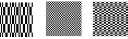
[image:1.595.202.418.576.643.2]In principle a single-pixel camera can use random patterns of structured light. In order to build a high-quality image of an object the number of random patterns needs to be of the order of hundreds of times the number of pixels in an image because the same information is typically gathered many times. Therefore, there is no time advantage over simple scanning of the scene. Faster computational imaging has been demonstrated when mutually orthogonal patterns were used to image a scene. For instance, one can distinguish the set of Hadamard patterns, which are binary and mutually orthogonal. Moreover, this set is complete in the sense that it is possible to decompose any image in terms of its elements. In the context of a single-pixel camera they are used in [2, 3]. We will provide the formal definition in Sec. III but we show some examples in Fig. 1. The number of the Hadamard patterns needed to create a faithful image is of the order of the number of pixels. Their advantages are explored also in the Hadamard spectroscopy [14].
FIG. 1: Examples of Hadamard patterns. Formal definition of these patters is given in Sec. III.
The Hadamard patterns can be easily realised optically by a digital micromirror device (DMD) using only binary operations, i.e., mirrors switched on or off [33]. In the present paper we allow for grey-scale patterns, suggested also by [15], that can be formed by the light reflected from the micromirror device in such a way that light from several mirrors could be directed on one pixel of the pattern. Alternatively, the grey scale signal from a given mirror can be formed by averaging the light over intervals of time in which the mirror is on and off. In [16] such spatial and temporal dithering is studied in order to perform the fast
Fourier transform. Application of the grey orthogonal patterns allows for greater flexibility in designing the patterns relevant for particular imaging problems and, in consequence, to speed up imaging. In reconstruction of an image from measurements of intensity for each mask we use a procedure provided in Appendix A.
We would like to stress the advantage that imaging with a single pixel camera with appropriate set of patterns can offer over imaging with standard multipixel cameras. This advantage can be expressed in terms of the processing cost and the memory needed for data processing. In standard multipixel cameras an image is first recorded in a memory and then analysed using methods of image post-processing. A single pixel camera can apply appropriate filters in pre-processing. It can extract the same information, for instance the position of an object, without the need for involving too much memory and computationally intensive processing. In this situation the post-processing is strongly simplified. So, the processing cost is reduced. It is also worth noticing that multi-pixel cameras can also introduce similar patterns to ones used by the single pixel camera at the level of data acquisition. However, processing of the data from all the pixels needs more memory and computational power. In our paper this pre-processing efficiency is demonstrated on the example of efficient localisation and orientation of faces.
B. Face Recognition
Face recognition is a well established field of research with many practical applications [17–23]. Compressed sensing methods are successfully applied to solve problems in face classification and recognition [24–27]. A single-pixel camera brings new possibilities into this field, especially in the speed of data acquisition and adaptivein vivoimaging or searched-face recognition. Proper patterns to provide the speed-up must be predefined, or decided quickly after a few initial measurements. In this paper, we use orthogonal grey-scale non-binary patterns forming a set in which the frontal view of faces is decomposed efficiently i.e., using a small numer of patterns, independently of the size of the face. In order to have such efficient decomposition the so-called eigenfaces can be used. The term eigenface reflects the fact that it is an eigenvector of a matrix formed from a library of faces, as formally defined in Sec. III, see examples in Fig. 2. For this set of patterns there exists a natural order of significance that allows for speeding the camera up if the object is a face vieweden face. However, the improvement is achievable only if the face is correctly localised and its position is determined. Therefore, we provide an algorithm for position and alignment determination that can be performed using only a few patterns. The eigenface basis is compared to the Hadamard basis and the advantage of the former is demonstrated in the context of the face imaging and validation based on compressive sensing. We test our methods using computer simulations of the scenario both without and then with a background ”random” image. The methods allow us to find and reconstruct a good quality image of a face that consists of32×32pixels within the field of view of the camera of dimensions64×64pixels. A standard single-pixel camera needs to take picture of entire4096pixel scene using a number of patterns of the same order. Due to our position- and alignment-finding schemes we image an arbitrary face using only about
[image:2.595.200.421.514.578.2]500patterns. Only 6 patterns allow us to determine one of64positions of the face in the field of view and one of180angles of its orientation. In other words we make six measurements to determine the position-orientation of the face from amongst a possible set of 11520 equally-likelya priori. The rest of the 500 are for producing the image. Furthermore, the total number of measurements required can be reduced significantly if instead of imaging a random face we merely have to pick out which face from a given list is actually observed. We observe that we need about200measurements to create good quality images. Then compressive sensing methods allow for proper verification with high probability using only about25measurements of random eigenfaces - a further increase in speed by a factor of 10.
FIG. 2: Examples of leading eigenfaces masks for the single-pixel camera as described in detail in Sec. III.
Scaling is another important feature that distinguishes the proposed algorithms for the single pixel camera from the ones based on Hadamard patterns. If the field of view is increased the number of Hadamard patterns required to find and image a face scales linearly with the number of pixels, i.e., with the square of the size of the field of view. Therefore, there is a trade-off between the image quality expressed in terms of resolution or the size of an object and the time needed to display an appropriate number of the Hadamard patterns. The proposed algorithms of position and orientation finding and face imaging based on eigenfaces do not depend on scales. Moreover if one correctly localises several faces, a scenario not considered in this paper, the number of measurements by a single pixel camera required to image all of them will scale with the number of objects, i.e., the faces, not with the number of pixels. Note that the proposed procedures could be complemented by a size estimation procedure. A simple one would check the intensity of the light for circular masks of several sizes centred at the point where the centre of light for the object is found. Sudden change of the intensity signals the edges of the object. Such a procedure allows for estimation of an approximate size in a number of steps that depends only on the ratio of the field of view to the object size and not on the number of pixels. Many such procedures can be defined and it is beyond the scope of this paper to analyse them in detail. For simplicity, in our simulations, we omit this (quick) extra step and fix the size of faces at32×32pixels and the field of view at64×64
The paper is organised as follows. First, in Sec. II, we address the problem of finding and aligning a face in the field of view of a single pixel camera. Face recognition in this same device is analysed in Sec. III based on the Hadamard and eigenface patterns. Finally, we compare the performance of the single-pixel camera in different scenarios, with random subsets of eigenfaces and Hadamard patterns applied for the discrimination of faces from a known list based on compressed sensing, Sec. IV.
II. POSITION AND ORIENTATION DETERMINATION BY SINGLE-PIXEL CAMERA
In order to achieve fast operation of the single-pixel camera with patterns tailored to a given type of object we need first to find the object in the field of view of the camera. In the following sections we show examples of efficient estimation of position and orientation parameters. The proposed techniques have been tested in computer simulations shown in supplementary material [28] using 32×32pixel images of real faces. The field of view was 64×64. The position finding method allows us to localise faces with 4 pixel accuracy. The orientation-finding protocol gives correct results with1◦precession with an accuracy of the same order. The accuracy limit is related to the fact that the real faces deviate from the assumed symmetries because of asymmetries either in their features or due to the uneven illumination of the tested images. In the simulations, the images of faces were cropped to fit the circle such that the orientation finding protocol relies only on the features of the face and not on the shape of the image.
A. Fourier based position estimation
In order to explain the idea of an object localisation we consider the one-dimensional case. The extension to two dimensions is straightforward. Our goal is to determine a shift parameterθof an unknown reflectivity functioncθ(x) = c(x−θ). The parameterθis a translation length with respect to the centre of the field of view of a single-pixel camera. We assume that the support ofcθ(x) =c(x−θ)is fully within the field of view of the camera, the background is uniform and that when the object is in the centre,θ= 0, the integrated light from the left and right from the field of view are equal. Other details of the function are irrelevant and estimation ofθis possible with onlytwomeasurements by the single-pixel camera.
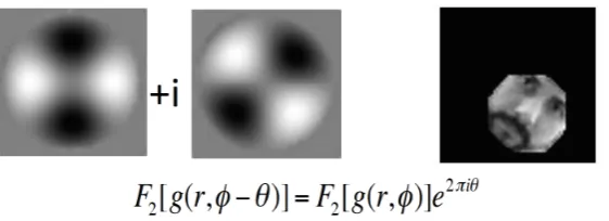
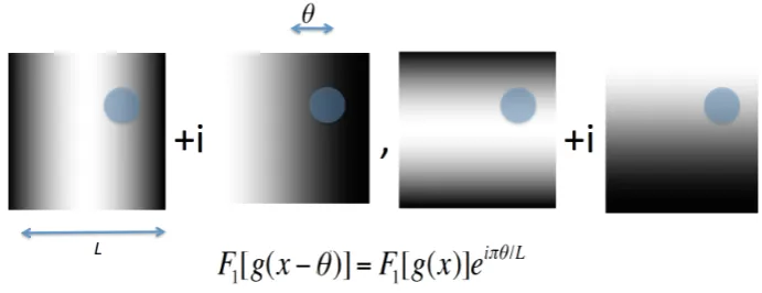
[image:3.595.135.481.499.632.2]For object localisation we use a simple fact that a phase of a Fourier component of a function carries information about the shift with respect to the position at which it would have zero phase. The phase can be used to determine uniquely the shift if the Fourier component has a period twice the size of the scene. It appears that measurements of only 4 masks, see Fig. 3 allow a single-pixel camera to uniquely find the position of the centroid of a face. The rigorous formulation of this statement is given in Appendix B. Notice that using this method we do not need to know detailed spatial structure of an object to determine its position in the field of view. Indeed, the procedure works accurately if the searched objects are symmetric with respect to their centres, or at least the intensities integrated along the vertical and horizontal axes are respectively described by symmetric functions. In practice this assumption is not satisfied exactly, as objects such as faces may deviate from perfect symmetries and may be non-uniformly lit. However, our simulations [28] show that the procedure is stable with respect to small deviations from symmetries. So, in spite of the small imperfections, we still obtain approximately correct position recognition.
FIG. 3: The phase of a low-frequency component of the Fourier transform of the field of view allows us to determine uniquely an arbitrary shifting parameter provided that the shifted object remains in the field of view. The Fourier component in one dimension can be measured with a single-pixel camera with only two masks. The equation shows the one-dimensional case. Generalisation to two dimensions is straightforward.
The Fourier based position recognition procedure for a single-pixel camera described above can be further improved if special more symmetric objects are searched.
Observation 1. If an object is characterised by a rotational symmetry and the field of view is square then only three measure-ments are enough to determine how it is shifted with respect to the centre of the field of view. See proof in Appendix C.
Moreover, the method is reduced to known centroid localisation procedure if no background is present.
respect to the centre of the camera. See the formal statement and the proof in Appendix D.
[image:4.595.138.476.205.300.2]The Fourier based position finding algorithm can also be applied in the situation where the face is in front of a known background [28]. The position of a face is determined from the phase of the difference of the Fourier components of the measured scene and the background alone, as shown in Appendix B. The errors of this estimation depend on the details of the background. In general the errors are smaller the more symmetric the part of the background covered by the face. Position-finding of faces with different backgrounds is demonstrated in the supplementary material movie files [28]. Single frames from these movies are shown in Fig. 4. Note that in the simulations we have used faces that are not perfectly symmetric and not uniformly illuminated. Therefore, sometimes we observe errors in the position estimation. However, the simulations allow us to conclude that the methods are robust enough to tolerate reasonable amounts of imperfections that may appear in practical applications.
FIG. 4: Computer simulations of localisation and imaging of a face by a single-pixel camera as in the supplementary material [28]. Left box: a face with a uniform background and the face localised and imaged by a single pixel camera. Right box: a face with a non-uniform background and the localised and imaged face. The background is assumed to be known. To localise the faces only 4 measurements by a single-pixel camera are needed.
For the sake of completeness we remark that alternatively to the Fourier based method of localisation finding, we can apply the nearest neighbour technique (NN), see for instance [21]. This method of image localisation is based on the least squared error discrepancy between the measured signal and one of the training images. The NN method can properly determine the position of an unknown symmetric object, see Appendix B. The NN procedure can be also applied to a single-pixel camera, however pre-measurements of a training object need to be performed which are not needed in the case of Fourier based procedure. We underline that in our simulations [28] we use only the Fourier based localisation method.
B. Fourier based orientation estimation
After finding the position of a given object in the field of view of the camera we need to find its orientation. We can use a scheme analogous to the position finding from Sec. II A. Again, the Fourier components, this time in the polar representation, are of importance as Fourier components of identical images but rotated with respect to each other differ solely by a phase factor. These estimators are not sensitive to the details of functions if only small frequency components are considered. To define the polar Fourier transform on a finite regionr < a, whereris the radial coordinate, let us define the following functions of the radiusrand the angleφ
νs,k=Ns,kRs,k xs,k
a
eikφ, (1)
whereNkis a normalization constant,Rs,k(r) =Jk( xs,k
a r)are the first order Bessel functions andxs,kdenotess-th zero ofJk. Finallyfs,kis a polar Fourier component of a functiong(r, φ)defined as
fs,k(g(r, φ)) = Z 2π
0 dφ
Z a
0
rdr g(r, φ)νs,k(r, φ). (2)
FIG. 5: The phase of the Fourier component allows us to determine uniquely the rotation angleθ ∈ [0, π). The Fourier component can be measured with a single-pixel camera with only two masks. The right image shows a shifted and rotated face. The rotation angle is recognised with1◦accuracy. The equation shows that the rotation parameter can be extracted from the phase of the Fourier component.
Alternatively again, we can apply the NN localisation method based on a set of training images, see Appendix E. The method correctly picks out the orientation of an unknown object with the same symmetry as a training object.
Summarising, finding the position and orientation of an object with a single-pixel camera using techniques described above requires only 6 measurements. This number can be shrunk to only 5 measurements if some redundancy in the position measure-ments is used to orientation estimation.
III. FACE IMAGING WITH SINGLE-PIXEL CAMERA
Given an image in a camera field of view that contains a face at a random position and orientation, after finding the face as described above we must turn to the next task in the chain - producing a high-quality image of the face that can be used to recog-nise it. As one of the most important advantages of the single pixel camera with respect to multi-pixel devices is more effective post-processing if the pre-processing is chosen appropriately, we investigate the rate at which particular goals are achieved by the camera with different types of patterns. In order to do this we compare the imaging performance of the single-pixel camera with patterns of eigenfaces with those based on Hadamard patterns (defined below). We compare eigenfaces with the Hadamard patterns in two situations. Either we choose the Hadamard patterns randomly (as would be the more likely case in the experi-mental situation) or post-selected, which discards those patterns that provide the lowest intensity readings. This information is not availablea prioriand so it really amounts to an image compression technique rather than imaging. Implementation of the patterns in terms of DMD configurations and the image reconstruction algorithm are described in Appendix A. For completeness of the discussion let us first formally define the Hadamard and the eigenface patterns.
The Hadamard patterns are formed from rows or columns of the Hadamard matrix that can be defined as a tensor power of a simple2×2matrix
1 1
1 −1
⊗n
. (3)
Different patterns of a DMD, after ordering their elements row by row in the form of one linear vector, correspond to different rows of the Hadamard matrix (3). The black regions in Fig. 1 correspond to -1 in (3) and mirrors switched off (in other words tilted so that the light reflected off them does not fall on the detector), while the white regions correspond to 1 in (3) and mirrors switched on.
In our analysis the eigenface patterns are formed as eigenvectors of vectorised and symmetrised images of faces from a database of 2414 training faces of 38 persons from [29]. This database contains images of frontal viewed faces of size32× 32 pixels in different lighting conditions. We build an orthogonal basis from the vectorised training images|ejiby taking eigenvectors of the following symmetric matrix
E=X
j
|ejihej|, (4)
where the Dirac notation is used. |ejiandhej|correspond to the column vector and its transpose respectively,|ejihej|denotes the tensor product. Standard methods of linear algebra allow us to diagonalise matrixE. As such it can be expressed as
E=X
j
aj|fjihfj|, (5)
detailed patterns do not have the required symmetries or structures typical in a face and so such an ordering is not particularly relevant or useful. The ordering of the eigenfaces therefore can significantly speed up imaging by the single-pixel camera, as shown by the following examples.
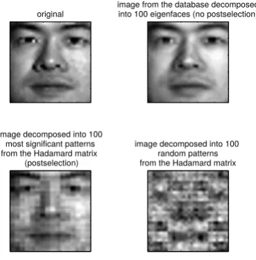
Example 1. Consider one of the faces from the database [29] used to construct the eigenfaces. We decompose it into 100 eigenfaces|fiicorresponding to the largest eigenvalues ofE in (4). A comparison with the decomposition with Hadamard patterns is shown in Fig. 6. Here, we show the decomposition using both the most significant and random Hadamard patterns. 100 eigenfaces gives better image than 100 of the most relevant Hadamard patterns.
original
image from the database decomposed into 100 eigenfaces (no postselection)
image decomposed into 100 most significant patterns from the Hadamard matrix
(postselection)
[image:6.595.226.411.187.375.2]image decomposed into 100 random patterns from the Hadamard matrix
FIG. 6:32×32pixels images enlarged 3 times. Upper left figure shows an original image from the Yale database of faces [29]. Upper right figure shows decomposition of this image into 100 leading eigenfaces built according to a scheme described in the main text (no postselection). Lower left figure: the image decomposed into 100 patterns from the Hadamard matrix set, but with postselection of the leading patterns. Lower right figure: the same with random patterns (without postselection).
Example 2. Consider a decomposition of a face not in the database. Reasonable image reconstruction is obtained from about 500 eigenvectors|fiiof Ein (4) corresponding to the largest eigenvalues. A comparison with the decomposition onto the Hadamard patterns is shown in Fig. 7. Here, we show the decomposition using both the most significant and randomly chosen Hadamard patterns. Both the eigenface and the Hadamard based methods give similar reconstruction qualityif the most significant Hadamard components are used. However, it should be emphasised that the most relevant Hadamard patterns are not a prioriknown, so such a reconstruction cannot be performed for an unknown face. Therefore the eigenface patterns normally provide better performance and speed than the Hadamard patterns in imaging of faces with the single-pixel camera.
IV. FACE RECOGNITION BASED ON COMPRESSED SENSING
In the previous section we have seen the reconstruction of 1024 pixel (32×32) greyscale image of a face from a known library based on the single-pixel camera with the leading 100 eigenvectors taken as patterns. Here, we show that if we wish to recognise a face from a particular set the correct face can be identified with significantly fewer measurements. To do this we apply a simple compressive sensing procedure for the single-pixel camera.
original
image from the database decomposed into 500 eigenfaces (no postselection)
image decomposed into 500 most significant patterns from the Hadamard matrix
(postselection)
[image:7.595.225.408.58.234.2]image decomposed into 500 random patterns from the Hadamard matrix
FIG. 7:32×32pixels images enlarged 3 times. Upper left: Original image of an arbitrary face not in the set of training images. Upper right: decomposition of this image into 500 eigenfaces built according to the scheme described in the main text (no postselection). Lower left: the image decomposed into 500 Hadamard matrix patterns with postselection. Lower right: the same with random patterns without postselection.
studied outside the context of the single-pixel camera in [25]. General definitions and properties from compressive sensing theory [2, 9, 11, 12, 30] are provided in Appendix F.
Let us consider in this context the problem of recognition of a face taken at random from a given list. Let a vector|sidescribe a position of a face on the list, e.g., the face numberi,|fiiis given by|si=|iiwith zeros everywhere but in positioniwhere it is equal to1. MatrixBbrings us from the space of the list position to the space of images of faces. It is given by
B =
K X
i=1
|fiihi|, (6)
wherehx|means the transposed vector|xi,K is the number of entries in the list. MatrixAdescribes the masks used by the single-pixel camera
A=
M X
j=1
|jihfj0|. (7)
Finally, if faceiis observed we haveM-dimensional observation vector
|oi=BA|ii. (8)
M×KmatrixBAis simply ”a catalogue” describing how the training faces from the list are expressed in terms of the measured patterns.
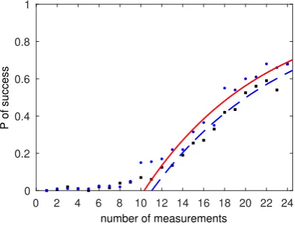
We determine the probability of correct face discrimination as a function of the number,K, of random Hadamard and random eigenface masks required to do this. To estimate the probability of success we randomly pick a face from the list. Next, we randomly chooseKmeasurement patterns, solve (F3) using a solver [31] and accept the answer if the Frobenius distance between the reconstructed face and the picked face is smaller than a fixed small value. In our case the value is 500 while the average total signal from all training images is about 2800. If two faces are less distant than this value human perception (the authors) indicates that they belong to the same person. We repeat this procedure for 200 randomly chosen faces from the list. The results are shown in Fig. 8 and 9.
The random eigenface patterns provide significantly better discrimination with a given number of measurements than the random Hadamard patterns. Figure 8 shows success probability as a function of measurement number with no detector noise. Figure 9 shows the situation with random normally distributed zero-mean noise introduced by the detector with the standard deviation of the order of one tenth of the signal. The probability of success is smaller than for the measurements without the noise Fig. 8, however the eigenfaces still perform better. To each plot we fit the function
g(x) = 1−e−M/p1+p2, (9)
0 2 4 6 8 10 12 14 16 18 20 22 24
number of measurements 0
0.2 0.4 0.6 0.8 1
[image:8.595.198.416.48.208.2]P of success
FIG. 8: Probability of successful face discrimination as a function of the number of measurements with the single-pixel camera using random eigenpatterns (dots) and random Hadamard patterns (squares). No detector noise is assumed. The probabilities are calculated based on 200 trials as described in the main text. The curves (9) are fitted to a part of the points. The fitting parameters (with95% confidence bounds) are: red solid line for the eigenface patterns,p1 = 10.2(9.0,11.6), p2 = 1.1(0.9,1.3), blue dashed line for the Hadamard patterns p1= 7.7(6.5,8.9), p2= 1.3(1.0,1.6).
0 2 4 6 8 10 12 14 16 18 20 22 24
number of measurements 0
0.2 0.4 0.6 0.8 1
P of success
FIG. 9: Probability of successful face discrimination as a function of the number of measurements with the single-pixel camera using random eigenpatterns (dots) and random Hadamard patterns (squares). Random zero-mean normally distributed noise with relatively large standard deviation of the order of one tenth of the signal. The probabilities are calculated based on 200 trials as described in the main text. The curves (9) are fitted to a part of the points. The fitting parameters (with95%confidence bounds) are: red solid line for the eigenface patterns, p1= 13.0(11.4,14.6), p2= 0.9(0.7,1.0), blue dashed line for the Hadamard patternsp1 = 11.7(9.9,13.5), p2= 0.9(0.7,1.1).
will increase greatly if a higher success probability threshold is desired. Conversely Fig. 8 implies that for lower probability of success the enhancement can be less than30%; the enhancement increases with the success probability. Depending on the application an end user may want a highly reliable face recognition procedure with a success probability above90%. The price for this is paid in terms of the number of measurements. Using both types of patterns the user needs a sufficiently high number of random measurements. However, as we demonstrate, the number is significantly lower if eigenfaces are used.
V. CONCLUSIONS
In this paper we have studied an efficient single-pixel camera scheme for face localisation, imaging, and recognition. Using computer simulations [28], we have demonstrated that the technique allows us to find a good quality image of a face that consists of32×32pixels within the field of view of the camera of dimensions64×64pixels. Application of localisation and orientation finding protocols as well as the eigenface patterns with a natural significance hierarchy allow for significant reduction in the number of measurements with respect to standard single-pixel camera methods. In the simulation we find an image of a face from the library used to build the basis of eigenfaces using only about206 patterns including only 6 patterns that allow for recognition of one of64positions of the face in the field of view and one of180angles of its orientation. If an arbitrary face not from the library is searched the number of measurement is about500. The standard single-pixel camera needs to take a picture of the entire4096pixel scene using a number of patterns of the same order. Moreover the number of patterns scale linearly with the number of pixels, while in the methods discussed in this paper scale linearly with number of objects, in this case faces.
[image:8.595.198.410.283.445.2]protocol depends on the symmetry of the part of the background which is covered by the face. In the ideal conditions the faces should be in frontal position, uniformly lit and the background should be uniform. These conditions depend on the arrangement of the camera users and, in potential practical applications, can be easily controlled. However, we also observe features of stability, i.e., small deviations from the ideal conditions are well tolerable and do not significantly influence the accuracy. We use computer simulations [28] to show working conditions of the protocols including effects of different lighting and uniform and non-uniform background. In potential practical applications, one can apply some background elimination techniques, for instance spectral filtering. However, we show that when the background is known and that part directly covered by the object is characterised by the same symmetry as the object the methods can be applied even when non-uniform background is present.
In this paper we have focused on just a single face in the field of view. The analysis of scenes with multiple faces can be achieved by a single-pixel camera applying different techniques, for instance inspired by modern image analysis and machine learning. Efficient software for a single-pixel camera is worthy of further investigation, but this extends beyond the scope of this paper.
In the context of face verification and discrimination we also show that compressive sensing methods allow us to recognise a face from the given list with high probability using only about 25 measurements of random patterns. We again observe that the eigenface patterns perform better than the Hadamard patterns, which are independent of the analysed subject.
Although we focus on the problems of face recognition, our procedures are easily generalisable to the recognition of other objects and in other fields. Instead of eigenfaces one could use orthogonal patterns appropriate to different objects under inves-tigation. Moreover, as the considered eigenfaces form a complete basis it is possible to exactly decompose any object or scene in this basis. However, it will be not the optimal decomposition as all eigenfaces may have significant influence into the imaging and the natural hierarchy may not be applicable. The localisation strategy can also be used in other contexts. For instance in determination of azimuthal position of an object by a radar if the intensity of the signal sent in different directions is shaped according to desired patterns. This information can be obtained using only one source of the signal and one detector at the same place. This technique could be also an alternative to the quadrant cell photoreceivers.
Although we do not demonstrate these results with a real optical set-up we believe that they will be of interest to experimental groups working on single-pixel camera applications. We further stress that here we are focused on principles of fast algorithms for this camera.
Acknowledgments
The work was supported by the QuantIC Project of the UK Engineering and Physical Sciences Research Council (EP/M01326X/1).
Appendix A: Orthogonal patterns formed by digital micro-mirror devices and image reconstruction
In what follows we represent a 2D pixelised grey-scale imageci,j, wherei, j= 1, . . . , Nby a real vector in the Dirac notation
|ciusing a standard vectorisation procedure(|ci)(i−1)N+j=ci,j. One can write
|ci=1|ci=X
i
|fiihfi|ci= X
i
αi|fii, (A1)
where1is an identity matrix,|fiiis an orthonormal basis of real, not necessary positive, vectors andαi =hfi|ciis the signal from the scene with the mask, measured by the single detector. Eq. (A1) represents the decomposition of an image in the orthogonal basis. Sinceαiis not necessarily positive we cannot measure it directly with a single-pixel camera. The intensity of light structured according to pattern|fiicannot be built directly either. To make our scheme measurable let us consider a set of shifted patterns defined as follows
|gii=β|1i+|fii, (A2)
whereβ is the absolute value of the smallest entry from all|fiiand |1i is a vector of ones (light fully reflected from the micromirror device and projected onto the imaged scene). Shifting the reference level is a standard concept used in the single-pixel camera based on binary patterns and it can easily generalised for cameras with grey scale patterns [15]. Notice that|giiare not orthogonal, however, they are positive vectors that represent the light patterns. An overlap of|giiwith|cigives us a positive coefficient equal to a signal from the camera that can be written as
hc|gii=hc|(β|1i+|fii) =βhc|1i+hc|fii. (A3)
Therefore, we can obtainhc|fiiused in Eq. (A1) as a function of the measurable quantities
hc|fii=hc|gii −βhc|1i. (A4)
Appendix B: Fourier based position estimation
Let us first consider the situation with uniform background.
Lemma 1. Consider a positive numberL, an arbitrary real functionc(x)that satisfiesc(x) =c(−x)and has support within the interval[−L/2, L/2]. The function shifted byθwith the support still within the interval[−L/2, L/2]isTθ(c(x)) =c(x−θ). The parameterθis determined by the formula
θ= L
πargf(Tθ(c(x))) (B1)
wheref(Tθ(c(x))) = R
dx Tθ(c(x))eixπ/L.
Notice that ifTθ(c(x))is a function of light reflectivity of an object shifted byθwith respect to the centre of anL-long field of view of the single-pixel camera, thenf(Tθ(c(x)))is a complex number, the real and imaginary parts of which are measurable by the camera using just two known patterns, thesin- andcos-shaped ones.
Proof. The symmetry of functionc(x)implies
Z
dx c(x) sin(xπ
L ) = 0, (B2)
thereforef(c(x))is real and positive. Asf represents a Fourier coefficient, by the shift theorem we have
f(Tθ(c(x))) =f(c(x))eiπθ/L. (B3)
This implies (B1). The condition on the support of the function guarantees the uniqueness of the solution.
Slight modification of this reasoning can be applied when there is a non-uniform, but known background described by intensity profileb(x). We define
c0θ(x) =
Tθ(c(x)) if x∈supp(Tθ(c(x)))
b(x) if x6∈supp(Tθ(c(x))) , c
00 θ(x) =
Tθ(c(x))−b(x) if x∈supp(Tθ(c(x)))
0 if x6∈supp(Tθ(c(x))) , (B4)
wheresupp(Tθ(c(x)))is the support of the function Tθ(c(x)). Function c0 describes an object with the background, while
c00, the modified object with the same support as the shifted object. By direct measurements by a single-pixel camera we determine Fourier componentsf of c0θ(x)andb(x). Their difference gives the Fourier component ofc00θ(x). Ifc00θ(x)has the same symmetry asTθ(c(x))its parameterθcan be determined by applying Lemma 1. Small deviation from the symmetry still allows for determination of the position, however the accuracy is reduced. This happens because the protocol determines the shift with respect to the place in which the phase of the Fourier component would be zero. This reference point corresponds to the centre of the field of view only if the object is symmetric. Otherwise the reference point is slightly shifted by an unknown distance which influences the accuracy.
Consider also the nearest neighbour method of localisation. This method allows us to find objects with a non-uniform back-ground if the observed imagectestis the same as the training imagectrainingor ifctrainingandctestare characterised by the same symmetry. Let us consider the second case. We measure a component of the Fourier transform ofTθ(ctraining)by measuring its overlap with the real and imaginary part ofeikxπ/L, whereLis the total length of the field of view of the camera. The minimum of the following function determines the sought positionθ1∈[−L/2, L/2)
Θ(θ) = kf(Tθ(ctraining(x)))−f(Tθ1(c
test(x)))k2
(B5)
= kf(Tθ(ctraining(x)))k2+kf(Tθ1(c
test(x)))k2−2|f(ctraining(x))||f(ctest(x))|cos(θ−θ
1−κ). (B6)
whereκ = arg(f(ctest)f∗(ctraining))is the joint phase of the Fourier components if the functions are in a position chosen as a reference from whichθandθ1 are measured. Immediate observation leads to the conclusion that ifctraining is the same asctestthenκ→0andarg minθΘ(θ)correctly estimatesθ1. Moreover, ifctestandctrainingadmits the same symmetry, i.e., ctest(x) =ctest(−x)andctraining(x) =ctraining(−x)thenκ= 0even if the functions are different. The formulaarg minθΘ(θ) is still a valid estimator of the unknown parameterθ1. If the assumptions on the symmetry are satisfied the minimization ofΘ(θ) gives us exact value of the searched parameter. If they are satisfied approximately the parameterκis non-zero and unknown precisely. This parameter determines the error ofθ1estimated by this method.
Appendix C: Proof of Observation 1
following four numbers
Ax(θ1) =
Z Lx/2
−Lx/2
dx dy c(x−θ1, y−θ2) cos(πx/Lx), (C1)
Bx(θ1) =
Z Lx/2
−Lx/2
dx dy c(x−θ1, y−θ2) sin(πx/Lx), (C2)
Ay(θ2) =
Z Ly/2
−Ly/2
dx dy c(x−θ1, y−θ2) cos(πy/Ly), (C3)
By(θ2) =
Z Ly/2
−Ly/2
dx dy c(x−θ1, y−θ2) sin(πy/Ly), (C4)
determining phases of the Fourier components in 2D space, carry all necessary information about the position of the function, i.e.,θ1andθ2.
If the object is characterised by a rotational symmetry andLx=Lythen
Ax(0) =Ay(0) =
p
A2
x(θ1) +Bx2(θ1) =
q
A2
y(θ2) +By2(θ2) (C5)
Equation (C5) is implied by symmetry assumption and the shifting theorem for Fourier components that says that a modulus of a Fourier component of a function is not changed if the function is shifted. Due to the constraint (C5) one measurement from the set (C1)-(C4) is redundant. The complex numbersAx(θ1) +iBx(θ1)andAy(θ2) +iBy(θ2)that carry information about the shift according to Lemma 1 can be determined from just three numbers.
Appendix D: Proof of Observation 2
Ifcis not characterised by rotational symmetry four measurements corresponding to (C1)-(C4) carry information about the asymmetry. This information can be erased taking the limitLx→ ∞andLy→ ∞as stated in Observation 2.
Proof. For largeLxandLywe can approximatesin(xπ/Lx)andcos(xπ/Lx)byxπ/Lxand1respectively. Then
π Lx
θ1≈tan
π
Lx
θ1
= Ax(θ1)
Bx(θ1)
= π
Lx R
dx dy c(x−θ1, y−θ2)x
R
dx dy c(x−θ1, y−θ2)
. (D1)
The last formula is just the horizontal coordinate of the centroid ofc. The integrals determine the total intensity reflected from the object described bycand the first moment of shiftedc. The same can be done for the vertical component. Since the total intensity of light is the same we do not need to measure it second time. Hence, only three measurements are needed to determine the shift of an unknown object in the field of view of a single-pixel camera with respect to its centre.
Appendix E: Orientation determination procedure
Lemma 2. Consider a real function in polar coordinatesc(r, φ). Assume that the function satisfiesc(r, φ) =c(r,−φ). Ifc(r, φ)
is rotated by an unknown angleφ1within the interval(−π/2, π/2], i.e.,Gφ1(c(r, φ)) =c(r, φ−φ1), parameterφ1is uniquely determined by the formula
φ1=
1
2argf1,2(Gφ1(c(r, φ))) (E1)
wherefs,k(Gφ1(c(r, φ)))are polar Fourier components.
Proof. Let us fix the radial mode s = 1 infs,k. Because of symmetry ofν1,2(r, φ) definingf1,2, see (1) and Fig. 5, and symmetry ofcthere exists common reference position in which the Fourier component has zero phase. For any rotation angle
φ1 ∈ (−π/2, π/2]with respect to the reference zero the phase of the Fourier component uniquely determines the rotation. Indeed, we can apply the shift theorem for the angular part of the transform, i.e.,f1,2(c(r, φ−φ1)) =f1,2(c(r, φ))e−i2φ1. As the phase off1,2(c(r, φ))is zero we have (E1). Again, symmetry ofν1,2(r, φ)andc guarantees that formula (E1) gives the unique solutions ifφ1lies within the interval(−π/2, π/2](without−π/2).
Alternatively, the nearest neighbour (NN) approach can be used to determine the unknown angle. We estimate that the sought angle is at the minimum of the squared error
Θn(φ) = n X
k=1
kf1,k(Gφ(ctraining))−f1,k(Gφ1(c test))k2
whereφ1 is an unknown angle of rotation by a rotation operatorGφ of a real imagectest that is known only approximately. Here,ctrainingis a training image. Fixing the radial modes= 1allows us to apply the shift theorem and determineφ1precisely ifctrainingis the same as the observed imagectestor at least ifctrainingadmits the same symmetry asctestas explained in the following example.
Example.Assume that an unknown imagectest(r, φ)is symmetric with respect to one reflection, i.e.,ctest(r, φ) =ctest(r,−φ). We can estimate uniquely an unknown parameterφ1 ∈ (−π/2, π/2]ofGφ1(c
test(r, φ)) = ctest(r, φ−φ
1)using only two measurements of a single-pixel camera, i.e., determining a phase of a proper mode of the polar Fourier transform. In the estimation we consider a known training imagectrainingand the following discrepancy function
Θ(φ) = kf1,2(Gφ1(c
test))−f
1,2(Gφ(ctraining))k2 (E3)
= kf1,2(Gφ1(c
test))k2+kf
1,2(Gφ(ctraining))k2−2|f1,2(ctest)||f1,2(ctraining)|cos(φ−φ1−κ), (E4) whereκ = arg(f1,2(ctest)f1∗,2(ctraining))is the joint phase of the Fourier components if the functions are in an orientation chosen as the reference. Ifctest andctraining have the same symmetry there exists a common reference orientation of both imagesctestandctrainingsuch that the Fourier component has zero phase in this orientation. Thenκ= 0andarg minφΘk(φ) is the correct estimator ofφ1even ifctrainingis not similar toctest. For objects symmetric with respect to one reflection axis, like faces, Fourier mode withk= 2allows for unique estimation of the unknown orientationφ1∈(−π/2, π/2].
Appendix F: Compressive sensing theory
Assume that we want to reconstruct an image of a signal as exactly as possible. Let us consider the signal represented as a vector, say in N dimensional space, x ∈ CN. Our reconstruction is based on the information from measurements. If a measurement is represented by a linear function of the signal the measurement results are represented by a vectory ∈ CM, whereM ≤N. The sampling vectoryis related to the signal according to
y=Ax,
whereAis anM ×N measurement matrix. The reconstruction problem consists of findingxknowingy. IfAis invertible then the reconstruction problem has an easy and unique solutionx = A−1y. It is not obvious how to find the solution ifA
is not invertible orM < N. In these cases findingxbased onyis in general an ill-defined problem, because it admits many inequivalent solutions. However, the problem can be well defined if the signal is sparse.
AnN dimensional vectorxis calleds-sparse if its non-zero components are spanned on at mosts-dimensional subspace. Alternatively, one can introduce the so called zero-norm as the dimensionality of the non-zero part of a vector
kxk0:= card(supp(x)) (F1)
and say that the vector iss-sparse ifkxk0≤s. It can be proved [30] that if for the measurement matrixAeach2scolumns are linearly independent thenxis uniquely reconstructed from2sdimensional measurement vectoryas the solution of the following problem
argminz∈CNkzk0 given that Az=y. (F2)
The above minimization is an NP hard problem, however, it can be substituted by another problem based on the linear program-ming. Indeed, it is proved that if the measurement matrixAsatisfies the so-callednull space property of orders(see [30] for rigorous definitions and proofs) then thexis uniquely reconstructed fromyas the solution of the following problem
argminz∈CNkzk1 given that Az=y, (F3)
where
kzk1:=
X
i
|zi|. (F4)
This problem is solvable using standard linear programming techniques. In many applications a matrix of random entries or randomly filled with 0 and 1 approximately satisfies the required conditions and can be used as measurement matrixA.
Often an image scenecis not sparse itself, however there exists ans-sparse representationzsuch thatc=Bz, whereBis an orthogonal matrix related to the change of representation. According to the compressive sensing procedures the scene can be uniquely found asBz, wherezis the solution of (F3) with the measurement matrixAB. The rows ofAcorrespond to the masks applied by the single-pixel camera. According to [9, 11, 12] ifABis a random matrix the correct reconstruction is achieved withM ≥O(dlog(N/s))with probability1−eO(−M).
[2] Duarte M F, Davenport M A, Takhar D, Laska J N, Sun T, Kelly K F and Baraniuk R G 2008 Single-pixel imaging via compressive samplingIEEE Signal Process. Mag.2583-91
[3] Edgar M P, Gibson G M, Bowman R W, Sun B, Radwell N, Mitchell K J, Welsh S S and Padgett M J 2015 Simultaneous real-time visible and infrared video with single-pixel detectorsSci. Rep.510669-1-8
[4] Shapiro J H 2008 Computational ghost imagingPhys. Rev. A78061802-1-4
[5] Erkmen B I and Shapiro J H 2010 Ghost imaging: from quantum to classical to computationalAdv. Opt. Photon.2405-50
[6] Welsh S S, Edgar M P, Bowman R, Sun B and Padgett M J 2015 Near video-rate linear Stokes imaging with single-pixel detectorsJ. Opt. 17025705-1-9
[7] Aspden R Set al.2015 Photon-sparse microscopy: visible light imaging using infrared illuminationOptica21049-52 [8] Chan K W C, OSullivan M N and Boyd R W 2009 Two-color ghost imagingPhys. Rev. A79033808-1-6
[9] Rudelson M and Veshynin R 2005 Geometric approach to error correcting codes and reconstruction of signalsInt. Math. Res. Not.64 4019-41
[10] Donoho D L 2006 For most large underdetermined systems of equations, the minimall1-norm near-solution approximates the sparsest near-solutionCommun. Pure Appl. Math.590907-34
[11] Candes E and Tao T 2006 Near-optimal signal recovery from random projections: Universal encoding strategiesIEEE Trans. Inf. Theory 525406-25
[12] Baraniuk R, Davenport M, DeVore R and Wakin M 2008 A simple proof of the restricted isometry property for random matricesConstr. Approx.28253-63
[13] Candes E and Tao T 2005 Decoding by linear programmingIEEE Trans. Inf. Theory514203-15 [14] Harwit M S and Slone N J A 1979Hadamard Transform Optics(London: Academic Press Inc.)
[15] Yu W-K, Liu X-F, Yao X-R, Wang C, Zhai Y and Zhai G-J 2014 Complementary compressive imaging for the telescopic systemSci. Rep. 45834-1-6
[16] Zhang Z, Wang X, Zheng G and Zhong J 2017 Fast Fourier single-pixel imaging via binary illuminationScientific Reports712029-1-9 [17] Sinha P, Balas B, Ostrovsky Y and Russell R 2006 Face recognition by humans: Nineteen results all computer vision researchers should
know aboutProc. IEEE941948-62
[18] Turk M and Pentland A 1991 Eigenfaces for recognitionJ. Cogn. Neurosci.371-86
[19] Belhumeur P, Hespanda J and Kriegman D 1997 Eigenfaces vs. Fisherfaces: recognition using class specific linear projectionIEEE Trans. Pattern Anal. Mach. Intell.19711-20
[20] He X, Yan S, Hu Y, Niyogi P and Zhang H 2005 Face recognition using LaplacianfacesIEEE Trans. Pattern Anal. Mach. Intell.27328-40 [21] Duda R, Hart P and Stork D 2001Pattern Classification, 2nd Edition(New York: John Wiley and Sons Inc.)
[22] Ho J, Yang M, Lim J, Lee K and Kriegman D 2003 Clustering appearances of objects under varying illumination conditionsProc. IEEE Int. Conf. Computer Vision and Pattern Recognition111-18
[23] Arisandi D, Syahputra M F, Putri I L, Purnamawati S, Rahmat R F and Sari P P 2018 A real time mobile-based face recognition with fisherface methodsJ. Phys.: Conf. Ser.978012038-1-7
[24] Wright J, Yang A Y, Ganesh A, Sastry S S and Ma Y 2009 Robust Face Recognition via Sparse RepresentationIEEE Trans. Pattern Anal. Mach. Intell.31210-27
[25] Yang A Y, Wright J, Ma Y and Sastry S S 2007 Feature selection in face recognition: A sparse representation perspectiveEECS Dep. Univ. of California, Berkeley Tech. Rep.UCB/EECS-2007-991-17
[26] Shi Q, Li H and Shen C 2010 Rapid face recognition using hashingProc. IEEE Conf. Computer Vision and Pattern Recognition2753-60 [27] Shi Q, Eriksson A, Hengel A, Shen C 2011 Is face recognition really a compressive sensing problemProc. IEEE Conf. Computer Vision
and Pattern Recognition553-60
[28] Roga W and Jeffers J 2018 Supplementary materials ...appropriate reference to be added...
[29] Belhumeur P, Hespanha J and Kriegman D 1997 Eigenfaces vs. Fisherfaces: Recognition Using Class Specific Linear Projection (Yale Face Database B,)IEEE Trans. Pattern Anal. Mach. Intell.711-20
[30] Foucard S and Rauhut H 2013A Mathematical Introduction to Compressive Sensing(Berlin: Springer)
[31] Wen Z, Yin W, Goldfarb D and Zhang Y 2010 A fast algorithm for sparse reconstruction based on shrinkage, subspace optimization, and continuationSIAM J. Sci. Comp.32, 1832-57
![FIG. 4: Computer simulations of localisation and imaging of a face by a single-pixel camera as in the supplementary material [28]](https://thumb-us.123doks.com/thumbv2/123dok_us/1411272.94017/4.595.138.476.205.300/computer-simulations-localisation-imaging-single-camera-supplementary-material.webp)