TITLE: DESIGN AND ANALYSIS OF PRODUCTION
TOOLING USING COMPUTATIONAL FLUID DYNAMIC
(CFD)
NAMA: MOHD FADZLI BIN TALIB
B051010257
UNIVERSITI TEKNIKAL MALAYSIA MELAKA
DESIGN ANALYSIS OF PRODUCTION TOOLING
USING COMPUTATIONAL FLUID DYNAMIIC (CFD)
Thesis submitted in accordance with the partial requirements of the
Universiti Teknikal Malaysia Melaka for the
Bachelor of Manufacturing Engineering (Manufacturing Design)
By
MOHD FADZLI BIN TALIB
Faculty of Manufacturing Engineering
UNIVERSITI TEKNIKAL MALAYSIA MELAKA
BORANG PENGESAHAN STATUS LAPORAN PROJEK SARJANA MUDA
TAJUK: DESIGN AND ANALYSIS OF PRODUCTION TOOLING USING COMPUTATIONAL FLUID DYNAMIC (CFD)
SESI PENGAJIAN: 2012/13 Semester 2
Saya MOHD FADZLI BIN TALIB
mengaku membenarkan Laporan PSM ini disimpan di Perpustakaan Universiti Teknikal Malaysia Melaka (UTeM) dengan syarat-syarat kegunaan seperti berikut:
1. Laporan PSM adalah hak milik Universiti Teknikal Malaysia Melaka dan penulis. 2. Perpustakaan Universiti Teknikal Malaysia Melaka dibenarkan membuat salinan
untuk tujuan pengajian sahaja dengan izin penulis.
3. Perpustakaan dibenarkan membuat salinan laporan PSM ini sebagai bahan pertukaran antara institusi pengajian tinggi.
4. **Sila tandakan ( )
SULIT
TERHAD
TIDAK TERHAD
(Mengandungi maklumat yang berdarjah keselamatan atau kepentingan Malaysia sebagaimana yang termaktub dalam AKTA RAHSIA RASMI 1972)
(Mengandungi maklumat TERHAD yang telah ditentukan oleh organisasi/badan di mana penyelidikan dijalankan)
Alamat Tetap:
G-75 BLOK 4 PERINGKAT 1 FELDA
BUKIT EASTER
81907 KOTATINGGI JOHOR
Tarikh: ________________________
Disahkan oleh:
Cop Rasmi:
Tarikh: _______________________
** Jika Laporan PSM ini SULIT atau TERHAD, sila lampirkan surat daripada pihak berkuasa/organisasi
UNIVERSITI TEKNIKAL MALAYSIA MELAKA
BORANG PENGESAHAN STATUS LAPORAN PROJEK SARJANA MUDA
TAJUK: DESIGN AND ANALYSIS OF PRODUCTION TOOLING USING COMPUTATIONAL FLUID DYNAMIC (CFD)
SESI PENGAJIAN:2012/13 Semester 2
Saya MOHD FADZLI BIN TALIB
mengaku membenarkan Laporan PSM ini disimpan di Perpustakaan Universiti Teknikal Malaysia Melaka (UTeM) dengan syarat-syarat kegunaan seperti berikut:
1. Laporan PSM adalah hak milik Universiti Teknikal Malaysia Melaka dan penulis. 2. Perpustakaan Universiti Teknikal Malaysia Melaka dibenarkan membuat salinan
untuk tujuan pengajian sahaja dengan izin penulis.
3. Perpustakaan dibenarkan membuat salinan laporan PSM ini sebagai bahan pertukaran antara institusi pengajian tinggi.
4. **Sila tandakan ( )
SULIT
TERHAD
TIDAK TERHAD
(Mengandungi maklumat yang berdarjah keselamatan atau kepentingan Malaysia sebagaimana yang termaktub dalam AKTA RAHSIA RASMI 1972)
(Mengandungi maklumat TERHAD yang telah ditentukan oleh organisasi/badan di mana penyelidikan dijalankan)
Alamat Tetap:
G-75 BLOK 4 PERINGKAT 1 FELDA
BUKIT EASTER
81907 KOTATINGGI JOHOR
Tarikh: ________________________
Disahkan oleh:
Cop Rasmi:
Tarikh: _______________________
DECLARATION
I hereby, declared this report entitled “Design and Analysis of Production Tooling using Computational Fluid Dynamic (CFD)” is the results of my own research except
as cited in the references.
Signature : ……….
Author’s Name : MOHD FADZLI BIN TALIB
APPROVAL
This report is submitted to the Faculty of Manufacturing Engineering of UTeM
as a partial fulfillment of the requirements for the degree of Bachelor of
Manufacturing Engineering (Manufacturing Design) (Hons.). The member of the
supervisory committee is as follow:
………
ABSTRAK
Projek ini adalah untuk merekabentuk dan menganalisis alat pengeluaran dengan
menggunakan pengairan dinamik bendalir atau CFD. Bongkah berbentuk ‘V’ acuan
pasir dipilih sebagai alat pngeluaran dan proses pembuatan untuk menghasilkannya.
Sebanyak tiga rekabentuk konsep acuan pasir telah direka untuk menghasilkan
bongkah berbentuk ‘V’ dengan menggunakan simulasi berasaskan komputer. Bahan
yang digunakan untuk menjalankan projek ini adalah Aluminium aloi (LM6) dan
Titanium Karbida. Tujuan projek ini adalah untuk merekabentuk dan menganalisis
alat pengeluaran dengan menggunakan pengairan dinamik bendalir (CFD). Oleh itu,
segala data dan informasi yang berkaitan dengan projek ini telah dicari dan
dicatatkan di dalam kajian literatur. Simulasi dan analisis yang akan dijalankan pada
projek ini dengan menggunakan perisian ANSYS dan perisian SolidWorks
digunakan sebagai perisian CAD untuk membina model tiga dimensi bagi reka
bentuk acuan pasir dan corak produk. Kaedah CFD akan digunakan bagi
mensimulasi aliran bahan cair memasuki dan memenuhi ruang dalam acuan pasir.
Analisis aliran FLUENT telah dijalankan ke atas ketiga-tiga konsep rekabentuk
acuan pasir dan keputusan dikira berdasarkan kepada enam parameter seperti tekanan
aliran, tenaga dalaman, halaju aliran, tenaga kinetic bergelora, nombor Reynold sel
dan tegasan ricih permukaan. Satu lagi matlamat daripada project ini adalah untuk
merekabentuk acuan yang terbaik untuk digunakan bagi meghasilkan produk acuan
pasir. Merujuk kepada keputusan yang diperolehi daripada analisa, rekabentuk acuan
terbaik dipilih dengan menggunakan kaedah pemilihan (pemilihan Pugh) dan konsep
ABSTRACT
This project is to design and analysis production tooling using computational fluid
dynamic (CFD). ‘V’ block and sand casting operation are selected as a production
tooling product and manufacturing process to produce it. Three sand casting moulds
are designed to cast the ‘V’ block using computer based simulation. The materials
that used for this project are Aluminum alloy (LM6) and Titanium Carbide. The
purpose of this project is to design and analysis of production tooling using
computational fluid dynamic. Thus, in the literature review, the data and information
that related is defined to accomplish this project. The simulation and analysis have
applied in this project using ANSYS software and SolidWorks software as a CAD
software to construct 3D modelling for mould design and product pattern. CFD
method is used to simulate the molten metal flow through the mould cavity for this
project. The FLUENT flow analysis has done on the all three concept designs and the
result is evaluated based on six parameters which are flow pressure, internal energy,
flow velocity, turbulence kinetic energy, cell Reynolds number, and wall shear stress.
Another aim of this project is to design the best sand casting mould are used to
produce the casting product. Based on the result, the suitable sand canting mould
design is selected using the selection method (Pugh Method) and the concept 1 has
DEDICATION
This report is specially dedicated to my parents whom has been there for me all the
ACKNOWLEDGEMENT
I would like to thank DR. Taufik for being an excellent supervisor of the project.
His overgenerous guide, conscious criticisms and tolerant support the writing of the
report in inestimable ways. His support of the project was greatly needed and deeply
be pleased about.
Other than that, thousands of gratitude dedicated to the technicians, friends and
TABLE OF CONTENT
Abstrak i
Abstract ii
Dedication iii
Acknowledgement iv
Table of Content v
List of Tables ix
List of Figures x
List Abbreviations, Symbols and Nomenclatures xiv
CHAPTER 1: INTRODUCTION 1
1.1 Background of Study 1
1.2 Problem Statement 2
1.3 Objective 3
1.4 Scope of the Project 3
1.5 Report Structural 5
1.6 PSM Planning Flow Process 6
CHAPTER 2: LITERATURE REVIEW 7
2.1 Casting 7
2.1.1 Type of Casting 8
2.1.2 Fluid Flow 13
2.1.3 Flow Characteristic 15
2.1.4 Heat Transfer 15
2.1.5 Flow Pressure 16
2.1.6 Internal Energy 17
2.1.7 Flow Velocity 17
2.1.8 Turbulence Kinetic Energy 18
2.1.9 Wall Shear Stress 18
2.2 Sand Casting 18
2.2.2 Component of Sand Casting 20
2.2.3 Sand 21
2.2.4 Defect of Sand Casting 21
2.3 Metal Metric Composite 23
2.3.1 LM6 24
2.3.2 Titanium Carbide 26
2.4 CAD Tool and Simulation and Analysis Software 27
2.4.1 SolidWorks 27
2.4.2 ANSYS Software 28
2.4.2.1 Computational Fluid Dynamic (CFD) 29
2.4.2.2. CFD Work principle 30
2.4.2.3 Advantages and Application 32
CHAPTER 3: METHODOLOGY 34
3.1 Flow Chart 34
3.2 Phase 1 36
3.2.1 Problem Identification 36
3.2.2 Literature review 36
3.3 Phase 2 37
3.3.1 Pattern Design 37
3.3.2 Mold Design 37
3.4 phase 3 39
3.4.1 Molten Metal Flow Simulation 39
3.4.2 Procedure of Flow Simulation Using ANSYS 41
3.5 Phase 4 54
3.5.1 Design Selection 54
3.5.2 Step in Pugh Concept Selection 55
3.5.2.1 Preparing the Selection Matrix 55
3.5.2.2 Rate the Concept 56
3.5.2.3 Rank the Concept 56
3.5.2.4 Combine and Improve the Concept 57
3.5.2.5 Select One or More Concept 57
3.6 Phase 5 58
3.6.1 Result and Discussion 58
3.6.2 Conclusion 58
CHAPTER 4: RESULT AND DISCUSSION 59
4.1 Design Sand Mould 59
4.1.1 Concept 1 60
4.1.2 Concept 2 62
4.1.3 Concept 3 64
4.1.4 Comparison among the Concept 66
4.2 Computational Fluid Dynamic Simulation Result (CFD) 67
4.2.1 Flow Pressure 68
4.2.1.1 Concept 1 69
4.2.1.2 Concept 2 71
4.2.1.3 Concept 3 73
4.2.1.4 Comparison Flow Pressure Between the mould 75
4.2.2 Internal Energy 76
4.2.2.1 Concept 1 76
4.2.2.2 Concept 2 77
4.2.2.3 Concept 3 78
4.2.2.4 Comparison Internal Energy Between the mould 79
4.2.3 Flow Velocity 80
4.2.3.1 Concept 1 81
4.2.3.2 Concept 2 83
4.2.3.3 Concept 3 85
4.2.3.4 Comparison Flow Velocity Between the mould 87
4.2.4 Cell Reynolds Number 88
4.2.4.1 Concept 1 89
4.2.4.2 Concept 2 90
4.2.4.3 Concept 3 91
4.2.4.4 Comparison Reynolds Number Between the mould 92
4.2.5 Turbulence Kinetic Energy 93
4.2.5.2 Concept 2 95
4.2.5.3 Concept 3 97
4.2.5.4 Comparison Turbulence Kinetic Energy Between the
Mould 99
4.2.6 Wall Shear Stress 100
4.2.6.1 Concept 1 100
4.2.6.2 Concept 2 101
4.2.6.3 Concept 3 102
4.2.6.4 Comparison Wall Shear Stress Between the mould 103
4.3 Concept Selection 104
4.3.1 Ranking Stage 104
4.4 Summary Result 106
CHAPTER 5: CONCLUSION AND RECOMMENDATION 108
5.1 Conclusion 108
5.2 Recommendation 109
REFERENCE 110
APPENDICES
A Gantt Chart
B Concept 1
C Concept 2
D Concept 3
E Result Concept 1
F Result Concept 2
G Result Concept 3
LIST OF FIGURES
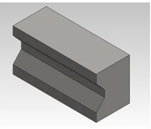
1.1 ‘V’ Block 4
1.2 Welding Fixture 5
2.1 Sand Casting 10
2.2 Shell Casting 10
2.3 Evaporative Pattern Casting 11
2.4 Plaster Mold Casting 11
2.5 Investment Casting 11
2.6 Ceramic Mold 12
2.7 Permanent Mold 12
2.8 Die 12
2.9 Centrifugal Mold 13
2.10 Illustration of Riser and Gating System 13
2.11 Temperature Distribution at The Mold 16
2.12 Outline af Production Step in a Typical Sand Casting Operation 19
2.13 Schematic Illustration of Sand Casting Mold 20
2.14 FLUENT analysis in bicycle 29
2.15 CFD Work Flow 30
3.1 Flow Chart of Methodology 35
3.2 Mold Design Concept 1 38
3.3 Mold Design Concept 2 38
3.4 Mold Design Concept 3 38
3.5 Flow Chart for Applying CFD 40
3.6 Ansys Workbench 14.0 Programs 41
3.7 Launch Fluid Flow (Fluent) Analysis 41
3.8 Creates Project Geometry 42
3.9 Import Geometry from External Resources 42
3.10 Select Drawing File 43
3.12 Edit Inlet for Name Selection 44
3.13 Edit Outlet for Name Selection 44
3.14 Change The Fluid/Solid Property 45
3.15 Launch Mesh 45
3.16 Edit Sizing Meshing 46
3.17 Launch Fluent Setup 46
3.18 General Setup 46
3.19 Turn on The Energy And Solidification & Melting 47
3.20 Insert Material Properties 49
3.21 Cell Zone Condition Setup 49
3.22 Boundary Condition Setup 50
3.23 Temperature Inlet 51
3.24 Outlet Boundary Condition 51
3.25 Wall Boundary Condition 52
3.26 Dynamic Mesh Setup 52
3.27 Monitor Setup 53
3.28 Solution Initialization 53
3.29 Run Calculation 54
4.1 Pattern Concept 1 Mould Design in Isometry View 60
4.2 Pattern Concept 1 Mould Design in Left View 60
4.3 Sand Mould Concept 1 Mould Design in Left View 61
4.4 Detail Drawing of Pattern Concept 1 Mould Design 61
4.5 Pattern Concept 2 Mould Design in Isometry View 62
4.6 Pattern Concept 2 Mould Design in Left View 62
4.7 Sand Mould Concept 2 Mould Design in Left View 63
4.8 Detail Drawing of Pattern Concept 2 Mould Design 63
4.9 Pattern Concept 3 Mould Design in Isometry View 64
4.10 Pattern Concept 3 Mould Design in Left View 64
4.11 Pattern Concept 3 Mould Design in Left View 65
4.12 Detail Drawing of Pattern Concept 3 Mould Design 65
4.13 Streamline Concept Mould Design 1 67
4.15 Streamline Concept Mould Design 3 68
4.16 Concept 1 Mould Design Flow Pressure in Contour View 69
4.17 Chart Molten Flow Pressure Vs Time for Concept 1 Mould Design 70
4.18 Concept 2 Mould Design Flow Pressure in Contour View 71
4.19 Chart Molten Flow Pressure Vs Time For Concept 2 Mould Design 72
4.20 Concept 3 Mould Design Flow Pressure in Contour View 73
4.21 Chart Molten Flow Pressure Vs Time for Concept 3 Mould Design 74
4.22 Chart Comparison of Molten Flow Pressure Vs Time between Concept
Mould 75
4.23 Concept 1 Mould Design Internal Energy in Contour View 76
4.24 Concept 2 Mould Design Internal Energy in Contour View 77
4.25 Concept 3 Mould Design Internal Energy in Contour View 78
4.26 Chart Comparison of Molten Internal Energy Vs Time between Concept
Mould Design 80
4.27 Concept 1 Mould Design Flow Velocity in Vector View 81
4.28 Concept 1 Mould Design Flow Velocity in Vector View for Critical Area 82
4.29 Chart Molten Flow Velocity Vs Time for Concept 1 Mould Design 82
4.30 Concept 2 Mould Design Flow Velocity in Vector View 83
4.31 Concept 2 Mould Design Flow Velocity in Vector View for Critical Area 84
4.32 Chart Molten Flow Velocity Vs Time for Concept 2 Mould Design 84
4.33 Concept 3 Mould Design Flow Velocity in Vector View 85
4.34 Concept 3 Mould Design Flow Velocity in Contour View for Critical Area86
4.35 Chart Molten Flow Velocity Vs Time for Concept 3 Mould Design 86
4.36 Chart Comparison of Molten Flow Velocity Vs Time between Concept
Mould Design 87
4.37 Concept 1 Mould Design Cell Reynolds Number in Vector View 89
4.38 Concept 2 Mould Design Cell Reynolds Number in Vector View 90
4.39 Concept 3 Mould Design Cell Reynolds Number in Vector View 91
4.40 Chart Comparison of Molten Cell Reynolds Number Vs Time between
Concept Mould Design 92
4.41 Concept 1 Mould Design Turbulence Kinetic Energy in Contour View 93
4.42 Chart Molten Turbulence Kinetic Energy Vs Time for Concept 1 Mould
4.43 Concept 2 Mould Design Turbulence Kinetic Energy in Contour View 95
4.44 Chart Molten Turbulence Kinetic Energy Vs Time For Concept 2 Mould
Design 96
4.45 Concept 3 Mould Design Turbulence Kinetic Energy in Contour View 97
4.46 Chart Molten Turbulence Kinetic Energy Vs Time For Concept 3 Mould
Design 98
4.47 Chart Comparison of Molten Turbulence Kinetic Energy Vs Time between
Concept Mould Design 99
4.48 Concept 1 Mould Design Wall Shear Stress in Contour View 100
4.49 Concept 2 Mould Design Wall Shear Stress in Contour View 101
4.50 Concept 3 Mould Design Wall Shear Stress in Contour View 102
4.51 Chart Comparison of Wall Shear Stress Vs Time between Concept Mould
LIST OF TABLES
2.1 Type of casting process 9
2.2 Casting defect 21
2.3 Compositions of LM6 24
2.4 LM6 properties 25
2.5 Titanium carbide properties 26
3.1 Material properties 48
3.2 Example of Pugh method 56
4.1 Difference between concept mould design 66
4.2 The result of flow pressure among the mould 75
4.3 The result of internal energy among the mould 79
4.4 The result of flow velocity among the mould 87
4.5 The result of cell Reynold number among the mould 92
4.6 The result of turbulence kinetic energy among the mould 99
4.7 The result of wall shear stress among the mould 103
4.8 Correlation between product objective and design parameter 104
4.9 The result of analysis among the mould 104
LIST OF ABBREVIATIONS, SYMBOLS AND
NOMENCLATURE
A - Cross Section Area of the Liquid Stream
CAD - Computer Aided Design
CFD - Computational Fluid Dynamic
D - Diameter Channel
MMC - Metal Matrix Composite
LM6 - Aluminum Alloy
TiC - Titanium Carbide
P - Pressure at the Elevation
Z - Elevation above a Certain Reference Level
U2 - Velocity of the Liquid at Elevation
G - Gravity Constant
- Density of the Fluid
Q - Volume Rate of Flow (m3/s)
V - Average Velocity of the Liquid in That Cross Section
Re - Reynolds Number
- Velocity of Liquid
- Density
- Viscosity of Liquid
Al - Aluminum
Cu - Copper
Mg - Magnesium
Si - Silicon
Fe - Ferum
Mn - Manganese
Ni - Nicel
Zn - Zink
CHAPTER 1
INTRODUCTION
In this chapter, background of this study is described according to the studies and
project preview. Problem statement of this project study is defined and stated in this
chapter. The scope of this project study and the project report organization are
described clearly. A Gantt chart also is shown in this chapter to monitor and
guideline for accomplishing this project.
1.1 Background of Study
Now days, production tooling is used widely in manufacturing field. For additional
information, production tooling is a working or manufacturing assistance of a
specialized nature which (unless substantially altered or modified) are limited in use
to a specific production line or the performance of a work. This project studied on
how to produce the part in production tooling. Production tooling is very important
to manufacture company because every part produced must be held while it is
machined, joined, or inspected or has any number of other operations performed on it
(Edward, 2011). So whether the part is big or small and simple or complex of an
operation, there is a need to accurately locate and secure properly using production
tooling such as clamping throughout the operation. Apart from that, the use of
production tooling can also increase the current degree of freedom to do work where
operators can do the assessment the right way and safely. Besides that, production
tooling is very effective for mass production and it is also one of the best ways to
The molten metal flow simulation is used to predict and determine the quality of the
product. This simulation is very necessary in this project to produce production
tooling. Thus, computational fluid dynamic is one of the methods for simulation
analysis. Computational fluid dynamic, which is known as CFD, is the analysis of
system involving fluid flow, heat transfer and associated phenomena such as
chemical reactions by mean of computer based simulation (Versteeg and
Malalasekera, 2007).
This project studies about design and analysis the molten matrix composite flow of
sand casting process which shows capability in designing the mould and its features
according to product requirement. This computer based simulation is important
because it can simulate the molten matrix composite filling into the mould cavity.
Furthermore, simulation and analysis of the thermal flow and the stress test can be
implemented into this project to detect any defect such as porosity that may happen
in the mould during the casting process. The result of this simulation is very
important to indicate the perfect the mould design and improvement can be done by
redesigning the mould without having to produce them.
This project presents the design and analysis of production using CFD. The
simulations of molten metal flow are studied.
1.2 Problem Statement
Many defects such as porosity, misrun, and scars occurred in the casting process are
probably due to the improper mould design. Besides that, molten metal flow and
solidification rate will affect by the improper mould design and indirectly the
turbulence flow will occur into the mould cavity. Impairments in mould design
cannot be traced without doing the simulation and analysis using computer based
simulation, such as CFD, on the mould design. In the traditional method, the testing
will be performed to the actual mould in order to determine whether the product is
casting mould in testing the mould to obtain the perfect one. Previously, CFD
method was widely used or applied on various range of industrial and non-industrial
application areas such as aerodynamics of aircraft and vehicle, turbo machinery,
metrology and biomedical and engineering but it was not widely used in
manufacturing fields especially in sand casting process (Versteeg and Malalasekera,
2007). From this situation, it is an approach and a challenge to apply this method in
sand casting operation to prevent or minimize the possibility of defecting in the
casting process. Therefore, the study of design parameters of the casting process for
production tooling is very important. The molten metal flow will be further
investigated.
1.3 Objective
The objectives for this project are:
a) To investigate the design parameter of sand casting in design production tooling.
b) To analyze the molten metal flow using computational fluid dynamic.
c) To design sand casting mould for production tooling.
1.4 Scope of the Project
Through this project, the material will be used as the molten metal is metal matrix
composite (MMC) which is LM6 and Titanium Carbide. It will focus on the sand
casting process as a medium to analyze and simulate the molten metal flow into
mould cavity.The ‘V’ block is used as acasting product that used as a clamp in the welding fixture to clamp various types of work-piece as shown in Figure 1.1 and 1.2.
CAD software such as SolidWorks is used to design and develop sand casting mould.
The design requires constructing the complete set sand casting mould includes
features such as air flask, pouring cup or pouring basin, sprue, runner system, riser,
cores, and vents (Kalpakjian and Schmid, 2010). The design also is done in three
reliability before processing into the actual condition. About three concepts of
moulds is designed and the best concept will be chosen using Pugh method selection.
Computational fluid dynamic (CFD) is chosen as a method to analyze and simulate
the molten metal flow using the software application, ANSYS to obtain the data for
future improvement of the sand casting mould. The parameter that are considered in
this analysis and simulation are flow pressure, flow velocity, internal energy,
[image:23.595.164.475.247.512.2]turbulence kinetic energy, Reynolds number, wall shear stress and mass of pattern.
Figure 1.2: Fixture welding
1.5 Report Structural
This report is divided into five major chapters which are known as introduction,
literature review, methodology, result and discussion, and conclusion.
a) Chapter 1: Introduction
This chapter explains about the background of the project, problem statement,
objectives and the scope of the project.
b) Chapter 2 : Literature review
This chapter explains and prove any information which is related to the project is
being studied and summarized it. By following from past studies, research and book,