i
SUPERVISOR COMFIRMATION
"I hereby declare that I have read this thesis and in my opinion this thesis is sufficient in terms of scope and quality for the award of a Bachelor of Mechanical Engineering
(Design & Innovation)."
Signature : ……….
Supervisor : DR SHAMSUL ANUAR BIN SHAMSUDIN
ii
DESIGN AND ANALYSIS OF SPEED LIMITER DEVICE FOR A VEHICLE
MUHAMAD SAUFI BIN ISMAIL
This thesis is submitted in fulfillment of the requirement for the degree of Bachelor of Mechanical Engineering (Design and Innovation)
Faculty of Mechanical Engineering Universiti Teknikal Malaysia Melaka
iii
DECLARATION
“I hereby declare that the work in this thesis is my own except for summaries and quotations which have been duly acknowledged.”
Signature : ………..
Author : MUHAMAD SAUFI BIN ISMAIL
iv
v
ACKNOWLEDGMENT
Alhamdulillah, I give thanks to the Almighty with His permission for me to complete this Final Year Project with excellent.
vi
ABSTRACT
vii
ABSTRAK
viii
TABLE OF CONTENTS
CHAPTER TITLE PAGE
SUPERVISOR DECLARATION i
DECLARATION iii
DEDICATION iv
ACKNOWLEDGEMENT v
ABSTRACT vi
ABSTRAK vii
CHAPTER 1 INTRODUCTION 1
1.0 Introduction 3
1.2 Problem Statement 3
1.3 Research objective 3
1.4 Research scope 3
1.5 Organization of the thesis 3
CHAPTER 2 LITERATURE REVIEW 4
2.1 Introduction 4
2.2 Vehicle speed limiting device 4 2.3 Speed limiter device working principles 5 2.4 Existing models of speed limiting device 5
2.5 Summary 6
CHAPTER 3 METHODOLOGY ` 7
3.1 Introduction 7
3.2 Methodologies process flow chart 7
3.3 Preliminary research 9
ix
CHAPTER TITLE PAGE
3.6 Houses of quality (HOQ) 11
3.7 Morphological chart 13
3.8 Concept selection 16
3.9 Design modelling 18
3.10 Summary 19
CHAPTER 4 DATA AND RESULT 20 4.1 Introduction 20 4.2 Data and analysis 20 4.2.1 Final design 21
4.2.2 Analysis on threaded shaft 28
4.2.3 Safety factor 34
4.2.4 Schematic diagram for speed limiter circuit 36 4.2.5 Coding on Arduino 37
4.2.6 Result on prototype 39
4.3 Summary 43 CHAPTER 5 DISCUSSION AND ANALYSIS 44
5.1 Introduction 44
5.2 Problem encounter 44
5.3 Summary 46 CHAPTER 6 CONCLUSION AND RECOMMENDATION 47 6.1 Conclusion 47
LIST OF FIGURE
BILL TITLE PAGE
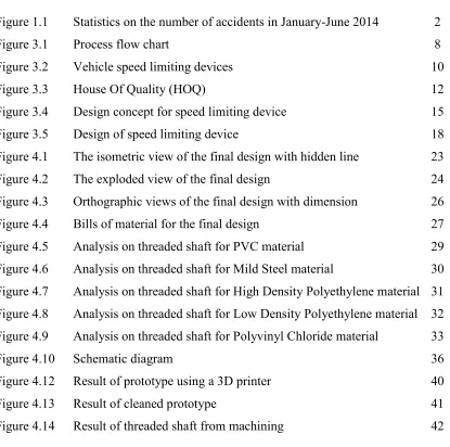
Figure 1.1 Statistics on the number of accidents in January-June 2014 2
Figure 3.1 Process flow chart 8
Figure 3.2 Vehicle speed limiting devices 10
Figure 3.3 House Of Quality (HOQ) 12
Figure 3.4 Design concept for speed limiting device 15
Figure 3.5 Design of speed limiting device 18
Figure 4.1 The isometric view of the final design with hidden line 23 Figure 4.2 The exploded view of the final design 24 Figure 4.3 Orthographic views of the final design with dimension 26 Figure 4.4 Bills of material for the final design 27 Figure 4.5 Analysis on threaded shaft for PVC material 29 Figure 4.6 Analysis on threaded shaft for Mild Steel material 30 Figure 4.7 Analysis on threaded shaft for High Density Polyethylene material 31 Figure 4.8 Analysis on threaded shaft for Low Density Polyethylene material 32 Figure 4.9 Analysis on threaded shaft for Polyvinyl Chloride material 33
Figure 4.10 Schematic diagram 36
[image:10.612.118.533.265.677.2]Figure 4.12 Result of prototype using a 3D printer 40
Figure 4.13 Result of cleaned prototype 41
LIST OF TABLE
BILL TITLE PAGE
1
CHAPTER 1
INTRODUCTION
1.0 INTRODUCTION
This undergraduate project entitles Design and Analysis of Equipment Speed limiter for the vehicle. The importance of this study is to intensify their efforts in reducing road accidents in Malaysia. As we know that the rate of road accidents recorded increased year by year and with this study can help the government deal with the issue. Many efforts have been undertaken by various parties, for example, in a tightening of the rules, giving the offense the summons speed limit, and also awareness campaign road. From the study of the speed limiter device, the speed of a vehicle can be controlled and thus it can minimize the number of road accident cause of lost control due to speeding.
This study aims to produce and design a control device speed limit and operate properly and also durable. Besides that, further study on real time speed of a vehicle and how to control the speed is taken deeply. This project will be carried out starting from concept selection process, material selection, prototyping, testing and up to the fabrication process. The previous draft was conducted by the Kuala Lumpur City Hall (DBKL) and the study linked to ensure this project is successful.
2
3
1.2 PROBLEM STATEMENT
A speed limiter is one of the product that exists and technically ours, but not in our country. Mostly the product placed inside the system of a vehicle transmission, such as in a throttle box. The speed of the vehicle exceeds the limit allowed by the government and a number of cases road accident rate is increasing every year and uncontrolled. So by design the speed limiter that applied on the throttle paddle, the problem can be reduced and controlled.
1.3 RESEARCH OBJECTIVES
For Undergraduate Project (PSM), there are several objectives to be implemented, among which are:
1. To study about the existing product of the speed limiter device 2. To design a product that functions as a speed limiter
3. To produce a model of prototypes that can demonstrate the function as well
1.4 RESEARCH SCOPE
Based on the knowledge of automotive and design study that related to fulfill the Dewan Bandaraya Kuala Lumpur (DBKL) requirement. The idea of this project will be translated into rapid prototyping and up to the testing process.
1.5 ORGANIZATION OF THE THESIS
4
CHAPTER 2
LITERATURE REVIEW
2.1 INTRODUCTION
This chapter will describe the scientific studies on matters connected with the vehicle speed limiter as described previously. A thorough review of existing products that help also adopted in this chapter. Therefore revenue for this study was quoted from the website, internet, reports pattern, thesis and journal also for the success of this PSM study. Among the matters to be discussed is the principle means that the speed limiter function, speed-limiting example of one of the existing, and also the weakness of existing tools, materials and lastly mechanism materials used.
2.2 VEHICLE SPEED LIMITING DEVICES
5
2.3 SPEED LIMITER DEVICES WORKING PRINCIPLE
Basic principles of vehicle speed limiter device is to maintain the speed of the car under a specified speed. This device is mounted on the throttle and the engine control system of the vehicle. If the vehicle exceeds a set speed, the engine control system will send a signal to the engine to filter the rates of oil entering the engine. With this, the vehicle speed is cut off and a safe speed can be kept.
2.4 EXISTING MODELS OF SPEED LIMITING DEVICE.
6
In addition, there is a system introduced by VDO. VDO road speed control is designed to maximize the efficiency engine of a vehicle. This device can control the top speed by detecting the vehicle road speed and comparing it to a set speed. The system works using the actuator which served as a tool to limit the enrollment rate by changing the fuel control lever on the injector pump. (Source: VDO (2008))
For this undergraduate project, which investigated the speed limiter device must be able to function properly when connected to any vehicle components and also be able to limit the speed of a vehicle if a certain speed limit set.
2.5 SUMMARY
7
CHAPTER 3
METHODOLOGY
3.1 INTRODUCTION
This chapter describes the methodology of the study will be conducted to obtain the vehicle speed limiting device specifications. The study includes a detailed knowledge of the design process and selection method. Many aspects need to be considered such as elegance, robustness, aesthetics, cost, resources, time, skill required and lastly safety. Good designers consider these universal design criteria when choosing which possible solution to implement.
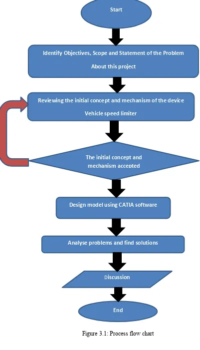
3.2 METHODOLOGIES PROCESS FLOW CHART
8
Identify Objectives, Scope and Statement of the Problem
About this project
Reviewing the initial concept and mechanism of the device
Vehicle speed limiter
The initial concept and mechanism accepted
Design model using CATIA software
Analyse problems and find solutions
Discussion
[image:19.595.117.518.54.755.2]End Start
9
3.3 PRELIMINARY RESEARCHES
In this initial study describes how the concept of the origin of this is performed by way of review of the movement and the speed limiting device mechanism. One reason why this concept under review is because in order to ensure the function of the limiting speed, and ensure that the target of the study is achieved. A more detailed study is made of the mechanism the tool to obtain accurate information and also reduce the problem at the next phase. This mechanism of the limiting devices is studied to help speed and simplify the process of designing.
3.4 THE CONCEPT OF EARLY RESEARCH
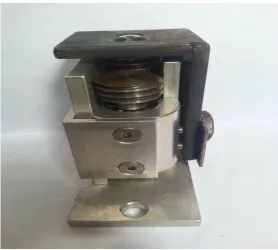
10
Figure 3.2: Vehicle speed limiting device
3.5 DESIGN PROCESS CONCEPT
11
3.6 HOUSE OF QUALITY (HOQ)
The House of Quality is a central tool of QFD, it translates customer requirements, market research and benchmarking data into prioritized engineering targets to be met by a new product design. Using house of quality (HOQ), it can help the process of selecting a concept once can produce a product that meets customer demand. Among the components contained in the house of this quality are the characteristics of engineering, benchmarking, position and direction of improvement, and customer needs. The conclusion of the house of quality methods used, the value of targets to be achieved to obtain design specifications can be obtained.
Figure 3.3 shows the methods used HOQ, where some aspect taken into account as an evaluation. Among the specification are taken into account at the component needs of customers is the method of installation, long life, safety, cost, and also stability. The other component is a weight factor for customer needs. The weight factor is to differentiate between the needs of customers that are important to customers. Measuring with a score of 1 to 5 were used as the evaluation scale. For component engineering characteristics contain the force applied, the weight of the product, product materials, product size and product design. For the specification of the characteristics of engineering, it is evaluated using a score of 1, 3 and 9 and there is a purpose for each score. For a score of 1 means that the specification was a much smaller role, followed by a score of 3 and also score 9. After that, the customer needs intersect with the engineering characteristics. Score in the specification engineering characteristics higher than the requirements of the customer. To get its customers' needs with the highest score is obtained by multiplying the weight factor and summing the total. Symbol of arrows in the HOQ is to show the engineering characteristics which need to be corrected or mitigated.
12 Engineering characteristic
Improvement directions n/a n/a ↓ ↓
Units N n/a n/a cm gm
Customer requirements Imp or ta nce w eig ht fa ct or For ce ap pl ied Mate ria l Produc t design Pro du ct si ze Produc t we ight
Assembly method 5 9
Material cost 5 9 3 9 1
Product lifetime 5 9 3
Stability 4 9 9 3 9
Safety factor 4 3 3 3 3
Method of use 5 9 3 1 1
138 126 69 98 22
30.5 27.8 15.2 21.6 4.9
1 2 4 3 5
Raw score
Relative weight
[image:23.595.113.525.65.691.2]Rank order
13
3.7 MORPHOLOGICAL CHARTS
A morphological chart is a table based on the functional analysis. Along the remaining side of the chart the functions are listed, while on the right side, different mechanisms which can be employed to execute the functions listed are made. It is a visual aid or writing help used to come up with different thoughts. The idea generation is achieved by creating single systems from different mechanisms illustrated in the morphological chart. It is proposed to generate several feasible designs using different mechanisms for each office for each concept.