Abstract- By using three properties of binary coded decimal (BCD) codes, BCD excess-3 code, and the overloaded decimal digit set (ODDS) code the parallel decimal multiplier is existed. In this paper Binary Coded Decimal-4221/5211 Partial Product Reduction block and normal decimal partial product tree using Overloaded Decimal Digit set (ODDS) is presented; it contains a binary Partial Product Reduction block, an unstable size Binary Coded Decimal-4221 counter block and a Binary Coded Decimal-4221/5211 partial product reduction block. These blocks were designed in Verilog language and implemented in FPGA Spartan-6.
Index terms—Parallel decimal multiplication, overloaded BCD representation, BCD -4221 and 5211, Radix-10 encoding.
I.INTRODUCTION
Binary arithmetic mentions converting and finding errors, but in decimal arithmetic is more demand in real time applications [1],[2].For decimal arithmetic operation decimal adders and multiplier are key components. Parallel decimal multiplication involves three stages: partial product generation (PPG), partial product reduction (PPR), Final addition of two Rows propagates digit addition. The sign-digit encoding[3],[4],[5],[6], redundant and non-redundant Binary Code Digit encoding pre-owned through digit multiplication.BCD-8421,4221,5211 are used for Partial Product Generation and Partial Product Reduction in non-redundant formats. BCD XS-3 digits ,ODDS are taken in the redundant decimal format to show the better presentation of BCD multiplication[3],[4],[7],[8]. (-3, 12) values are taken by XS-3 code in PPG circuit. In binary PPR tree the ODDS is used in Partial Product Generation method. The multiplicand X and multiplier Y are encode by Binary Coded Decimal number as X (0, 9) and Y (0, 9) in 4-bit binary system. In multiplier Sign Digit-Radix-10 encoding is considered in PPG stage. [3],[4],[9],[10],[11],[12].In SD-radix-10 encoding the Binary Coded Decimal number is restructured to a set (-5,5) from original set of (0,9).For the generating of multiplicand multiplies in PPG stage then BCD-4211/5211 are generated for the better performance of PPG circuit SD-Radix encodingBCD-4211/5211 recoding are suggested[11],[12],[13]. The main drawback by Binary Coded Decimal-4221/5211 codes in a Partial Product Generator is 3X multiples does not achieved in without carry method from redundant radix -10[4].
Revised Manuscript Received on December 22, 2018.
First Author name, His Department Name, University/ College/ Organization Name, City Name, Country Name.
Second Author name, His Department Name, University/ College/ Organization Name, City Name, Country Name.
Third Author name, His Department Name, University/ College/ Organization Name, City Name, Country Name.
The XS-3 PPs can be defined as Overloaded Decimal Digit Set Partial Products by summing a pre-determined modified term. The
Partial Product Reduction method is outlined because the Overloaded Decimal Digit Set Partial Product Reduction tree once the input signals are ODDS digits. An improved Partial Product Generator circuit supported redundant BCD coding is projected for PPG; the improved parallel selection decimal addition is determined for final adder to additional improves in execution from multiplier. The 16x16-bit decimal multiplier supports in which changes Partial Product Generation design, a converted decimal addition and therefore the before 17:2 Overloaded Decimal Digit Set Partial Product Reduction tree is [14] introduced in additional consideration and with improved figures.
II.BCD MULTIPLIER USING BOTH REDUNDANT AND NON-REDUNDANT BCD CODES
Here the both weighted and non weighted four-bit codes in decimal digit are exists and the codes having five or above bits. [15] Has studied the variation between BCD codes in full feature. Self-complementing has nine’s complement of every decimal bit is gained by changing into bits through coded form of that bit. A Signed Digit radix-10 recoding changes a four-bit Binary Coded Decimal multiplier digit Yi (Yi €{0,1,2,...,8,9}) to SD radix-10 digit Ybi (Ybi €{-5,-4,-3,....3,4,5}). Every digit Ybi is can be written by five multiple select signals {Y1i, Y2i, Y3i, Y4i, Y5i} and a sign bit Ysi. Selection control signals are called choice of signals for the five to one MUXs for choose the +ve multiplicand multiples. When Ysi=1, a -ve multiplicand multiple is created by bit changing of the +ve Binary Coded Decimal-4221 coded and summing one at the Least significant bit.
In [11], [12], BCD-4221 the +ve multiplicand multiples are coded . 2X is built by 3 steps: transforming Binary Coded Decimal-8421 to Binary Coded Decimal-5421, BCD-5421 is shifted to left of 1-bit to Binary Coded Decimal-8421 and transforming Binary Coded Decimal-8421 to Binary Coded Decimal-4221. 4X is created from 2Xx2. 5X is gained by a three-bit changed to left of Binary Coded Decimal-4221 to Binary Coded Decimal-5211 and then transforming Binary Coded Decimal-5211 to Binary Coded Decimal-4221. A carry-save formula supported Binary Coded Decimal-4221/ 5211 is employed for PPR [11], [12]. All columns of the Partial Product row are compact to 2 digit number by a cipher P: 2 Carry Save Adder; decimals are occurred through adjacent bit columns. The 4-bit 3:2 Carry Save Adder are created the 4 full adders & Binary Coded Decimal-4221 to Binary Coded Decimal-5211
convertor.
Design of Hybrid BCD Code Based Parallel
Decimal Multiplie
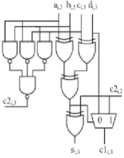
Fig 1. 3:2compressor for operand code inBCD-4221.
The digit 3:2 Carry Select Adder is employed to get the bit p: 2 Carry Select Adder to scale back Partial Product rows to 2 decimal bits Hi and Si. In Figure.1 a decimal 3:2 Carry Save Adder supported on Binary Coded Decimal-4221 has considered. The binary carries Hi€[0,9] (hi,3, hi,2, hi,1, hi,0) created by four-bit 3:2 Carry Save Adder needed for multiplication by two . A 2 x Hi may be attained by changing the Binary Coded Decimal-4221 to Binary Coded Decimal-5211s (intimated by Wi) and shifting to left of Wi
by one-bit. Results are coded as Binary Code Decimal-4221.
III. REDUNDANT BCD CODES OF RADIX-10
MULTIPLICATION
The Binary Code Decimal-4221 and Binary Code Decima-5211 decimal encrypting were taken in partial product generation and partial product reduction [11], [12]. They introduced before, drawback of the Binary Code Decimal-4221/ 5211 code are used a non-redundant radix-10 number in group of (0, 9) 3X digit is not achieved in a without carry method. A decimal Sign Digit illustrations depend upon a redundant number set to permit free-carry addition [3], [4], [7], [16], [6]. To present a summary in Sign digit Radix-10 multiplication exploitation redundant Binary Code Decimal codes [4]. The multiplier [4] includes three important types: The radix-10 Partial Product Generation stage supported redundant Excess-3 and Overloaded Decimal Digit Set, the Overloaded Decimal Digit Set Partial Product Reduction tree and also the Binary Code Decimal Adder.
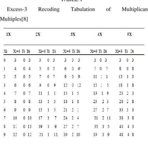
[image:2.595.325.543.112.351.2]The Sign Digit radix-10 decimal multiplier factor mistreatment redundant Binary Code Decimal codes [4] is in Figure. 2. A Sign Digit radix-10 recoder and Excess -3 coding were used in a quick Partial Product Generation stage, during in positive number multiples are taken during a without carry ; the –ve multiples will gain through bit changing of the comparing +ve and adding +1 to Least Significant Bit. The Excess-3 Partial Products will have diagrammatic as Overloaded Decimal Digit Set Partial Products done through summing correction conditions (i.e., summing all -three constants). The (d+1) Partial Product rows supported Overloaded Decimal Digit Set illustration have been compacted till the two 2d-digit decimal Partial Products are in employing a (d+1):2 Overloaded Decimal Digit Set Partial Product Reduction tree. These 2 Partial Product rows are gathered through the final decimal carry propagation. The partial product generation method involves a Sign Digit Radix-10 recoding, 3 blocks for selection the multiples and generating of the multiplicand multiples .The Excess-3
recoding is utilized [4] to create the multiplicand multiples in a without carry. Excess-3 Recoding table form of multiplicand multiples is as shown in Tabulation-1. A Excess-3 bits NXi can be written by:
Figure 2. The multiplier design using redundant Binary Code Decimal code.
N x Xi + 3= Di+10 x Ti (1)
Here Ti is decimal carry (0<Ti<Tmax).Tmax is decimal carry that is
larger feasible number .Di mentions decimal number from
-3<Di<12-Tmax.
TABLE 1
Excess-3 Recoding Tabulation of Multiplicand
[image:2.595.305.544.453.688.2]IV. BY USING HYBRID BCD CODES OF DECIMAL
MULTIPLIER
[image:3.595.321.553.294.491.2]The developed 16X16-digit (compared with [14]) decimal multiplier. Hybrid design is defined, due to utilization of binary, Binary Code Decimal-8421,4221/5211,5421, Overloaded Decimal Digit Set, XS-3 and excess-6 codes [14]. T In Figure. 3 decimal multiplier is shown. Based on previous paper the ODDS PPR tree is done [14]; a binary PPR tree block & a non-fixed size BCD-4221 counter block and a BCD-4221/ 5211 PPR tree block involves in ODDS PPR tree. The Partial Product Generator circuit derived from redundant Overloaded Decimal Digit Set codes & the considered XS-3 Illustration is done in this works. A conditional speculative decimal adder utilizes decimal addition depends upon a carry-select adder design. The CSA block in [10], [11], [12], [14], [17] has complexity in gates to form carry signals, the carry network in advanced design also uses this structure to withstand the delay between the decimal carry-select adder block and the PPF carry network . The system in Partial Product Generator method and the Binary Coded Decimal adder method enhances the decimal multiplier performance.
Figure 3. The Advanced hybrid decimal multiplier using Binary Coded Decimal codes.
As specified above, the PPG stage consists of the,forming the multiplicand multiples Signed Digit radix-10 recoder, and selection of multiples three blocks. Both the multiplicand multiples generation block and Signed Digit radix-10 recoder block are used in the advanced PPG circuit. To decreases the multiple of multiplicand multiples with the functions of the blocks in the Partial Product reduction The Partial Product Generator circuit uses a Signed Digit radix-10 recoder are shown by the following steps:
(1) A usual (d+1):2 binary Cary Save Adder tree is reprocessed to compress the d+1 Overloaded Decimal Digit
Set Partial Product rows into two Partial Product rows . The carry and sum signals are described in Binary Coded Decimal-4221 recoding.
(2) A Binary Coded Decimal-4221 counter block sums the bit that takes initiated between multiplication by six (6) and the digit columns in the binary Carry Save Adder tree is achieved. (3) The Binary Coded Deciaml-4221 PP in steps (1) and (2) are summed by a 3:2compress to acquire the last 2d-digit Partial Products where carry is H and sum is S. Before summing carry and S each decimal bit Hi should be multiplied by 2. The Partial Product array of a 16x16digit multiplier is 17. The Partial Product Reduction tree where the column height is given in Fig. 4. ODDS format are coded in the input signals of the Partial Product Reduction tree . A 17:2 Partial Product Reduction tree block involves of a Binary Coded Decimal-4221 counter block, a 17:2 binary PPR tree and a 6:2 Binary Coded Decimal-4221/5211 Partial Product Reduction tree. It has four binary compression levels in17:2 binary Carry Save Adder tree .
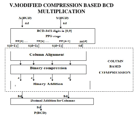
V.MODIFIED COMPRESSION BASED BCD MULTIPLICATION
Fig5.Binary decimal compression based BCD multiplication.
Binary to Decimal (BD) Compression Techniques:
By using Binary to Decimal compression 2-bits column-based binary operations and BD conversions can be achieved. The input for the above techniques was the outcomes of 1 × 1 bit Binary Coded Decimal multiplier which were introduced in binary format, and the output of this technique is in Binary Coded Decimal design. The technique achieves the upcoming steps:
1) Arranging the input operands formed on two-digit decimal point. The Same 2-digit decimal point should have same column in each operand.
2) Compacting all operands in Every columns by binary compressors
3) Every column using binary adders the compressed binary operands are accumulated.
4) Changing binary sum into decimal in every column where 2-digits as sum and other digits as carry.
5) The decimal sums and carries are Retained in CS format for all columns based on their
decimal positions
and binary code decimal multiplier, partial product are mixed in binary format are occupied .Two steps are achieved known as partial product compression and conversion to reduce the number of PPs .
PP-Compression: A PP-compression achieves compression for the binary operands in every column using coherent binary compression and some accumulation methods. Then, these binary operands after the compaction are added in binary to achieve a binary sum. Here m operands were compacted to a single for every columns.
PP-Conversion: A PP-conversion transforms binary sum into decimal operands. In all column, the column-based operations generate less size binary sums.
FDA:
To achieve last outcome of the Binary Coded Decimal multiplier, the decimal operands produced next to PPR should be added to decimal adders.
VI.(17:2)BINARY PARTIAL PRODUCT
REDUCTION TREE:
[image:4.595.318.534.56.215.2]From the Figure.4, It can be conclude that the 4 compression levels were spotted in the (17:2) Partial Product Reduction tree. The input Partial Product named as first, second, third and fourth and the levels are 17, 9, 6 and 4, particularly. From (4:2) compressor the nine Partial Product lines are achieved by the first (16:8) reducing level. (3:2) compressor the second (9:6) compression is composed in (3:2) and the 6 Partial Product rows were produced. (6:4) compression level produces 4 Partial lines. The last two Partial Product lines are created by the final (4:2) compression level and the final (4:2) compression level in the ith point in figure 6 it is mentioned; where it involves 4 binary (4:2) compressors. From the final compression level, Both Partial Product lines along the weights of 2, 4,8,16 for the C output signal and weights of 8, 4, 2, 1 for the sum signal are produced. The C and S signals are mentioned in four Binary Coded Decimal-4221 and Binary Coded Decimal-4221.
Figure 6. 4:2 compressors of 4-bit binary.
The binary Partial Product Reduction are reprocessed to decimal Partial Product Reduction method; Although, we need +6 correction terms when all decimal carry came. During the final 4:2 compression level in Figure. 6, here one +6 carry correction term in cout2 is needed. Larger no’s of carries relocated that are intermediate of adjoining bit columns of binary seventeen to two Carry Save Adder is 14. These carries are labelled as Ci+1(0:13). In
figure.7 the 4:2 compressor reprocessed in the binary Partial Product Reduction tree is mentioned .
Figure. 7. 4:2 compressor using NAND and XOR gates.
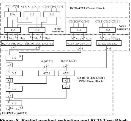
(1) A binary ODDS counter , exists in 3:2 carry save adder the Binary Coded Decimal-4221 counter is most proper in comparison .
(2) The separation between of 8-bit counter and the 14-bitcounter and the two 3-bit counters which can withstand over paths in Partial Product Reduction tree of non- fixed size of Binary Coded Decimal-4221 counter that decreases the critical path delay in the decimal 6:2 Partial Product Reduction tree.
[image:4.595.74.272.270.478.2] [image:4.595.371.495.362.520.2]Figure 8. Partial product reduction and BCD Tree Block.
[image:5.595.63.284.370.538.2]The 17:2 reduction blocks and counter block generates a four BCD-4221 for increase height columns and five Binary Coded Decimal-4221 terms. The 6-digit decimal were shifted to 6:2 Binary Coded Decimal-4221/5211 to generate the final two Partial Product rows in Partial product Reduction. The 6:2 Binary Coded Decimal-4221/5211 Partial Product Reduction block, the slow output is mixed to the fast inputs that are upcoming in the 3:2 Carry Save Adder to withstand the criticalpath delay mentioned in figure 8.
Figure.9. decimal Adder using 2digit binary code.
The critical path in delay for a 4-bit decimal CSA contains of a one-stage of XOR gate, one-stage OR gates, and a two-stage ANDOR-Inverter gate according to [17]. A 16x16-bit multiplier contains of a seven stages of AND-OR gates and a one-stage of OR gate. The delay in critical path gathered place in the Partial Product Format block. The block for the 2d digit Binary Coded Decimal adder is mentioned in the Figure. 9. The the carry production signal p and carry generation signal g are placed by the equal invert functions of p and g. The OR Inverter gate and the OR-AND Inverter gate are taken in PPF levels. The AND Inverter gate and the AND-OR Inverter gate are used in the place of before operator in the even Partial Product Format.
VI.RESULTS / COMPARISION:
The proposed 16x16 multiplier is verified logically using
Xilinx14.7.Its simulated results are shown in figure 10.
Figure10: simulation result proposed of 16x16 multiplier.
The modified 16x16 multiplier is verified logically using Xilinx
[image:5.595.304.549.449.588.2]14.7.Its simulated results are shown in figure 11.
Figure 11: simulation result of modified 16x16 multiplier.
Comparison of LUTs, power dissipation and path delays with
respect to multiplier is as shown in Table 2.
Scheme Slice Total slice Utilization Path
LUTs used LUT present delay
Proposed
16x16 2865,720 5% 16.095ns
Multiplier
Modified
16x16 145 5,720 2% 10.043ns
Multiplier
_________________________________________________
VII.CONCLUSION
By Xilinx 14.7 software simulation work has confirmed has that is fixed in multiplier is much speed and lesser area from before state structures.
REFERENCES:
1. M. F. Cowlishaw, “Decimal floating-point: Algorism for computers,” in Proc. 16th IEEE Symp. Comput. Arithmetic, Jul. 2003, pp. 104–111.
2. M. A. Erle, B. J. Hickmann, and M. J. Schulte, “Decimal floatingpoint multiplication,” IEEE Trans. Comput., vol. 58, no. 7, pp. 902– 916, Jul. 2009.
3. M. A. Erle, E. M. Schwarz, and M. J. Schulte, “Decimal multiplication with efficient partial product generation,” in Proc. 17th IEEE Symp. Comput. Arithmetic, Jun. 2005, pp. 21–28.
4. A. Vazquez, E. Antelo, and J. Bruguera, “Fast radix-10 multiplication using redundant BCD codes,” IEEE Trans. Comput., vol. 63, no. 8, pp. 1902–1914, Aug. 2014.
5. T. Langand A. Nannarelli, “A radix-10 combinational multiplier,”inProc.40thAsilomarConf.SignalsSyst.Comput.,Oct.2006, pp.313–317.
6. A. Svoboda, “Decimal adder with signed digit arithmetic,” IEEE Trans. Comput., vol. C-18, no. 3, pp. 212–215, Mar. 1969.
7. S. Gorgin and G. Jaberipur, “A fully redundant decimal adder and its application in parallel decimal multipliers,” Microelectronics J., vol. 40, no. 10, pp. 1471–1481, Oct. 2009
8. R. D. Kenney, M. J. Schulte, and M. A. Erle, “High-frequency decimal multiplier,” in Proc. IEEE Int. Conf. Comput. Des.: VLSI Comput. Process., Oct. 2004, pp. 26–29.
9. [9].T. Langand A. Nannarelli, “A radix-10 combinational multiplier,” in
Proc.40thAsilomarConf.SignalsSyst.Comput.,Oct.2006,pp.313–317. 10. G. Jaberipur, and A. Kaivani, “Improving the speed of parallel decimal
multiplication,” IEEE Trans. Comput., vol. 58, no. 11, pp. 1539–1552, Nov. 2009.
11. A. Vazquez, E. Antelo, and P. Montuschi, “A new family of highperformance parallel decimal multipliers,” in Proc. 18th IEEE Symp. Comput. Arithmetic, Jun. 2007, pp. 195–204.
12. A. Vazquez, E. Antelo, and P. Montuschi, “Improved design of high-performance parallel decimal multipliers,” IEEE Trans. Comput., vol. 59, no. 5, pp. 679–693, May 2010.
13. A. Vazquez and E. Antelo, “Multi-operand decimal addition by efficient reuse of a binary carry-save adder tree,” in Proc. 44th Asilomar Conf. Signals Syst. Comput., Nov. 2010, pp. 1685–1689. 14. X. Cui, W. Liu, W. Dong, and F. Lombardi, “A parallel decimal
multiplier using hybrid binary coded decimal (BCD) codes,” in Proc. 23rd IEEE Symp. Comput. Arithmetic, Jul. 2016, pp. 150–155. 15. R. K. Richards, Arithmetic Operations in Digital Computers.
Princeton, NJ, USA: D. Van Nostrand Company, Inc., 1955. 16. B. Shirazi, D. Y. Y. Yun, and C. N. Zhang, “RBCD: Redundant binary
coded decimal adder,” IEE Proc.-Comput. Digit. Techn., vol. 136, pp. 156–160, Mar. 1989.
17. A. Vazquez and E. Antelo, “Conditional speculative decimal addition,” in Proc. 7th Conf. Real Numbers Comput., Jul. 2006, pp. 47–57.
18. D. Radhakrishnan and A. Preethy, “Low power CMOS pass logic 4-2 compressor for high-speed multiplication,” in Proc. IEEE Midwest Symp. Circuits Syst., 2000, pp. 1296–1298.