Lifetime Evaluation and Management for Class 1 Piping of Korean Lead Plant
Chang Y.S °, Jin T.E l), Song T.H 2), Jeong I.S. 2)
1) Power Engineering Research Institute, Korea Power Engineering Company, Korea 2) Korea Electric Power Research Institute, Korea Electric Power Corporation, Korea ABSTRACT
A previous feasibility study for the Korean lead plant, PLiM Phase I, showed a strong possibility of continued operation beyond the original licensed period. In 1998, PLiM Phase II study was initiated aimed at performing additional detailed evaluations on a wider range of components. The objective of this paper is to present the Korean PLiM efforts for Class 1 piping which is identified as one of the critical components with regard to long-term operation. The key findings such as typical design features, degradation mechanisms, technical issues, draft results from the lifetime evaluation and effective management programs for Class 1 piping of the lead plant are briefly described and discussed.
INTRODUCTION
In early 1990's, Korean plant lifetime management(PLiM) study for pressurized water reactor(PWR) has been performed. The objectives of PLiM Phase I were to carry out a feasibility study for continued operation of Korean lead plant and to evaluate the aging effects of 13 major components[1 ]. PLiM Phase II was launched following the feasibility study. Work scope and schedule for the Phase II have been determined considering the results of Phase I and change of Korean regulatory environment. In the initial stage of PLiM Phase II, a vast amount of efforts were mainly devoted to investigate technologies and to reflect US experiences. License renewal application(LRA) reports[2, 3] of Calvert Cliffs and Oconee plants as well as a series of license renewal industry reports have been reviewed. Additionally, draft standard review plan(SRP)[4] in accordance with 10 CFR 54 and generic aging lessons learned(GALL) program report[5] prepared by Nuclear Regulatory Commission(USNRC) have also been reviewed. Though, unlike the US, an extended operation periods of NPPs are not definitely prescribed in Korea, utility may achieve the continued operation through 10-year periodic safety review(PSR) that adopts similar methodologies for lifetime evaluation and management. The purpose of this paper is to present the Korean PLiM efforts for Class 1 piping which is identified as one of the critical components because it includes safety-related components relied upon to remain functional during and following design-basis events.
PLiM Strategy
PLiM has a strong possibility to not only solve the plant aging and maintenance obsolescence but also provide the vision for the continued operation beyond the original licensed period. The primary goal of PLiM is to operate nuclear power plants(NPPs) safely and economically for the design life of the plants. If this primary goal is achieved, then the operation of NPPs beyond the design life will be pursued as the secondary goal. The secondary goal of the PLiM study is to operate plants for their optimum lifetime. The feasibility of continued operation for the lead plant in terms of technical, regulatory and economic aspects was established in Phase I. In the Phase II, detailed lifetime evaluation and establishment of aging management program of the 10 SSCs(3 components and 7 commodity groups) have been performed. The PLiM implementation plan will be developed in the near future based on the results obtained in these preceding efforts.
Technical Guideline
Technical guidelines were developed in order to provide procedures for lifetime evaluation and management of the major 10 SSCs[6]. These can be utilized for Korean PWR NPPs generically after being reviewed by a panel of technical experts. In general, the technical guidelines are divided into four sections; sub-component screening, age-related degradation mechanism identification, lifetime evaluation and aging management program establishment. The lifetime evaluation and management for Class 1 piping of the lead plant were performed followed by the corresponding one of these technical guidelines.
SMiRT 16, Washington DC, August 2001 Paper # 1611
BOUNDARIES AND SCOPE
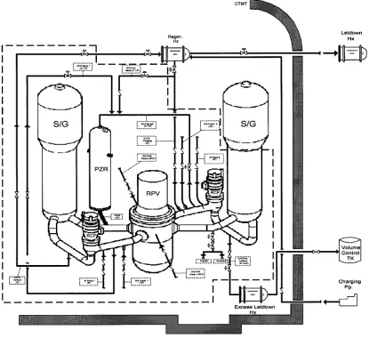
The Class 1 piping and associated components comprise of subcomponems, including the reactor coolant(RC) loop piping, branch connections and nozzles, and associated Class 1 valves. These items are generally required to perform the safety functions of maintaining the RCS pressure boundary, maintaining core cooling and preventing the release of fission products. Only those parts that are passive in nature and directly support the accomplishment of a safety function require evaluation as a subassembly. Fig. 1 is a schematic diagram of the lead plant identifying most of the locations for the Class 1 piping addressed in this paper.
I I
I I I I I I I I I I I I I I I I I I I
I "
I
[-~,~--,[
i :.3.~..J
I
Regen.
H x
[?.f.~!!]
,_.=.:;,..~.~.,
=--=,=--=
I I ~'1
N ,
F'=;7,-'~';'I, . . . "'L._."~...=
l . . , ~ . = . , , ' , . .
~"~i CTMT : : : : : : : : : : : = : : : = : : : : : : : : =:==:: : : = : : : : : : = : : :=:::= : : : = : : ====:: : : : : : : : : : = : : : : : = : : iiiiii : : : : : : :=:==: : : : : : : = : : : : : : : : : : : = : : : : : : : : : : : : : : : : : : : : : = : : : : : = : ::==:: : : : : : : : : : : : : : = : : : : :=::== :=:::= : : : : : = :==::: : = : : : : : : : : : : :::=:= ==:::: : : : : : : : : : : : : : : : : : : : : : : : = : : : : : = : : : : : = : : : : : = : : : : : = ==:::: : : : : : = : : : : : = : : : : : = : = : : : : : : : : : = : : : : : : : : : : : = ::=::= ::::== : : : : : = =::::= : : : : : = ::=::= ::=::= : : : : : = :=:::= : : : : : : ::=:== ::::== ::=::= ::::== :::=:= ::=::= :==::: ::==:= ::=::= iiiiii ==1::: iiiii! =:==:= = : : : : : : : : : : = :=:=:= : : : : : : : : : : : = = : : : : : : : : : : = : : : : : = : : : : : : : : : : = : : : : = : : : : : : : : : : : : : : : : : : : : : : : : : : : : : : : : : : : : : : : : : : : : : : = : : : : : : : : : :=:=:= : : : = : : : : : : : : Letdown H x S/G : : : : : : : : : : : : . . . . . .
' - I
I
I
I
I
I
j
i
I
I
I
t = = * * , , i L"="'"~J I
I : : : : : : ::1::1
: : : : : : :::=1: : : : : : 1 iiii~i :::==: : : = : : : ::1=:: ::==:: ::=:== : : : : : : : : : : : : ::=::= : : : : : = =:::1: iiiiii iiii!i :::::= . . . . . .
Excess Hx Letdown I ~
. . . : : : : : : : : : : : : : : : : : : : : : : : : : : : : : : . . . . . . ! • Charging Pp.
[Note] Scope • Class 1 piping, nozzles, and Class 1 valves within the dotted line
Fig. 1 Schematic Diagram for Class 1 Piping and Associated Components of the Lead Plant
The three principle components of RC loop piping are the hot leg connecting the reactor pressure vessel(RPV) outlet and the steam generator(SG) inlet, the crossover leg pipe connecting the SG outlet to RCP suction, and the cold leg pipe connecting the RCP outlet and the RPV inlet. The branch connections and nozzles connect various subsystems and piping to the main RC loop. The scope of these items includes the nozzle and piping up to the Class 1 boundary for the system. The Class 1 valves contain three pressure boundary components including the valve body, bonnet, and closure bolting. The valves provide isolation as well as control functions for the RCS.
DESIGN INFORMATION
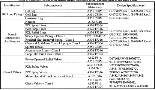
The RC loop pipe and fittings are made of stainless steel. The piping is centrifugally cast and the fittings are statically cast except for splitter elbow design that consists of a two-piece construction. The Class 1 valve bodies are also stainless steel and either statically cast or forged. Most of the subcomponents are designed for 650°F and 2485psig except pressurizer spray lines, surge line and relief lines. These lines are designed for 680°F and 2485 psig. Table 1 identifies the applicable design information for each component including the subcomponent material and design specification.
Table 1. Summary of Subcomponents Requiring Aging Effect Management of the Lead Plant
Identification
RC Loop Piping
Branch Connections And Nozzles
Class 1 Valves
Hot Leg Cold Leg Crossover Leg Nozzles
Subcomponent Subcomponent
Material(s) A351 CF8M A351 CF8M A351 CF8M A182 F316
PZR Spray Lines A376 TP304
PZR Surge Lines A376 TP316
PZR Relief Lines A376 TP316
Safety Injection Piping - Class 1 Residual Heat Removal Piping - Ch Chemical & Volume Control Piping
Class 1
Loop Fill/Drain Lines - Class 1
Class 1
A376 TP304/316 A376 TP316 A376 TP304
Splitter Elbow A351 CF8M
Accumulator Lines - Class 1 A376 TP316
,ool A376 TP304
Power-Operated Relief Valves PZR Safety Valves
PZR Spray Valves
Motor Operated Block Valves Check Valves - Class 1
Class 1
A182 F316, A351 CF8M A351 CF8M, A105 Gr.II A376 TP316
A182 F316 A516 Gr.65, A182 F316, A376 TP304
Design Specification(s) G-679079 Rev.0, G-676580 Rev.2, G-676342 Rev.4, G-679192 Rev.1, G-676343 Rev.3
G-676262 Rev.3, G-677129 Rev.2, GEC-REL 199NF0003,
GEC-REL 199NF0004,
G-676580 Rev.2, G-676342 Rev.4, G-676343 Rev.3
D 176615 (WNES676270), 93-13507(WNES676258), H52137(WNES672679), A843 l(WNES676270), 78907-9(WPSI676258), A8482/A8456/A8474/A8421 (WNES676270),
78704(WPSI676241),
94-12892/94-13304(VW43670)
The welding processes[7~9] used to fabricate the lead plant RC loop piping included gas tungsten arc welding(GTAW), shielded manual arc welding(SMAW), and submerged arc welding(SAW). The GTAW process was used for root closure welds and small girth welds. The GTAW process yields a high-quality weld with a slow deposition rate. During welding, inert gas shields the weld against air. The SAW process was used on large girth shop welds for pipe-to-fitting welds as well as pipe-to-pipe welds. Non-destructive Examination(NDE) applied to pipes, fittings, and welds include through PT, MT or RT.
HISTORY OF AGE-RELATED DEGRADATION
AGING MECHANISMS/EFFECTS REQUIRING MANAGEMENT
In the initial stage, eight potential aging mechanisms and effects were reviewed based on the major overseas results[ 1~5, 10] and industry issues described in aging management review(AMR) report[ 11 ]. As a result of this review, the following four major aging mechanisms that should be managed were derived in order to maintain the integrity of Class 1 piping and associated components during the continued operation period.
Fatigue
Fatigue has been recognized for many years that a metal subjected to a repetitive or fluctuating stress will fail at a stress much less than that required to cause fracture on a single application of load. The important factor in fatigue failure is stress repetition. The specific effects of fatigue are cracks in the material that may or may not be detected before mechanical failure. After repeated cyclic loading of sufficient magnitude, microstructural damage can accumulate, leading to macroscopic crack initiation at the most affected locations. Subsequent mechanical or thermal cyclic loading can lead to growth of the initiated crack. Thus, the evaluation of potential fatigue damage is also a technical issue affecting the continued operation of Class 1 piping and associated pressure boundary components of the lead plant.
Thermal Aging
The only significant effect of thermal aging with respect to degradation of Class 1 piping and component materials is embrittlement of CASSs. CASSs are duplex structures consisting of austenite and ferrite. At high temperatures, the ferrite undergoes complex phase changes, often resulting in hardening of the ferrite. This, in turn, usually produces a small increase in tensile strength and a reduction in fracture toughness, often as much as an order of magnitude. The reduced fracture toughness causes a reduction in the critical flaw size for the piping, which is defined as the size flaw that could lead to failure. The embrittlement is usually characterized by a period of time at a temperature for which little or no embrittlement occurs, followed by a dramatic exponential type reduction in toughness. It is only in the last decade that a significant effect of thermal aging has been observed for longer times at operating temperatures of light water NPP primary coolant loops(525°F to 620°F). These observations have led to considerable concern for the CASS product forms in the primary coolant loops of PWRs. Welds in the primary loop also thermally age but usually respond more slowly due to low ferrite[ 11 ].
Wear
Wear occurs in parts that experience intermittent relative motion, in clamped joints where relative motion is not intended but may occur due to a loss of clamping force, or via flow-induced vibrations. A limited number of the RCS component parts are subjected to relative motion. Class 1 valve closure parts, such as the cover and bonnet flanges, the body flanges, and the closure bolting, are subject to some degree of relative motion if preload is lost if infrequent disassembly and reassembly operations occur. Loss of material due to wear could cause leakage for these closure elements. Mechanical wear is not significant for Class 1 piping and the associated pressure boundary component or component parts, with the exception of the Class 1 valve closure elements such as the cover and bonnet flanges, the casing and body flanges, and the closure bolting. These effects are managed by following the current and effective programs of periodic ISI and testing for the detection and evaluation-repair-replacement of the closures.
Stress Relaxation
LIFETIME
EVALUATION AND MANAGEMENTIn order to demonstrate the integrity of Class 1 piping and associated components during the continued operation, huge works for screening and scoping of the components, lifetime evaluation and establishment of aging management program has been performed. From these activities, total 142 aging mechanism/subcomponent group - combinations(Aging Codes) were derived and pre-evaluation were carried out to identify the Aging Codes needed for further detailed lifetime evaluation and aging management. The detailed lifetime evaluation were performed for important two aging mechanisms(24 Aging Codes); the one was fatigue evaluation for Class 1 piping and the other was susceptibility evaluation of thermal aging for CASS components(piping and fittings). Followed by the pre and detailed evaluations, new aging management programs(e.g., fatigue monitoring and augmented ISI) are being developed. The remaining two aging mechanisms and effects can be managed by current aging management programs.
Fatigue Re-analyses
All of the RC loop and BOP Class 1 piping, nozzles and Class 1 valves of the lead plant were designed to the requirements of USAS B31.1 Code for Pressure Piping[12]. The current licensing basis(CLB) is somewhat different with the nowadays design requirements(e.g., ASME Section III). Also, a current operating basis includes any inservice examination requirements(e.g., ASME Section XI) and any licensing commitments related to fatigue(e.g., monitoring of operating transients). Thus, it is necessary to demonstrate the adequacy of the CLB during the continued operation period.
The ASME Section III Code requires a design analysis for Class 1 components to address fatigue and establish limits such that initiation of fatigue crack is precluded. Fatigue usage factor is a final output of explicit fatigue analyses in accordance with ASME Section III. However, the fatigue integrity was implicitly addressed in original design of the lead plant since designed by early B31.1 Code. In part for the B31.1 Code, design requirements assume a stress range reduction factor to provide conservatism in the piping design to account for thermal fatigue due to thermal cyclic operation. This reduction factor of 1.0 provided the number of anticipated cycle is limited to 7000 equivalent full temperature cycles.
Regarding the fatigue design margins inherent in Class 1 piping system components constructed to B31.1 rules, the EPRI performed several efforts in conjunction with the DOE/SNL[13]. The intent was to show where inherent conservatism exists, and to identify if there are certain situations where the B31.1 evaluation may not provide adequate assurance of fatigue resistance. The selected piping systems were chosen to be representative of systems with locations of high usage factor and with a range of geometric features and loading conditions. The evaluation results showed that the fatigue usage factor for Class 1 piping systems designed prior to about 1980(most plants in nowadays) is very conservative compared to the fatigue usage factor computed using the current version of the ASME Section III. The conclusion was that piping systems designed to the requirements of ANSI B31.1 are adequate for continued service in nuclear plants.
There are two structural analysis reports[ 14, 15] that contain RC loop piping stress analyses results according to B31.1 before and after the steam generator replacement of the lead plant. The results of these reports and additional further efforts showed that the calculated thermal expansion stress did not exceed the allowable thermal expansion stress range for not only the design life but also additional 20-year operation as well. Thus, in fatigue aspects, it is anticipated that the integrity of RC loop piping is remain valid during the continued operation. However, until this time, it is not easy to find fatigue related plant specific design documents for BOP Class 1 piping, nozzles and Class 1 valves of the lead plant.
Considering this situation, fatigue re-analyses according to ASME Section III were carried out to demonstrate the integrity of Class 1 straight pipes, elbows, butt welds and nozzles after adopting somewhat conservative assumptions[11, 16~18]. Prior to the main stress analyses, several sensitivity analyses were performed to find out optimum finite element(FE) models(e.g., ligament effects and thermal sleeve effects). Fig. 2 shows the typical FE models and boundary conditions used for stress analyses of the lead plant Class 1 nozzles.
The cumulative usage factors from the fatigue re-analyses results were, in most cases, less than unity except Pressurizer relief line elbow and butt weld, and safety injection(SI) accumulator nozzle etc. In general, i.e., the results showed a prospective view when considering the conservative assumptions. Though, fatigue re-analyses for valves, piping socket welds, and reducers were not performed, this issue will be resolved through an implementation of fatigue monitoring program for limiting locations derived from the representative fatigue re-analyses results and preceding experiences. Therefore, it is anticipated that the integrity of Class 1 piping and associated components regarding fatigue issue will be maintained during the continued operation period.
(a) Full model of Surge Nozzle (b) Full model of Charging Nozzle
(c) 1/4 model of Surge Nozzle (d) 1/4 model of Charging Nozzle
Fig.2 Finite Element Models and Boundary Conditions
Susceptibility Evaluation of Thermal Aging
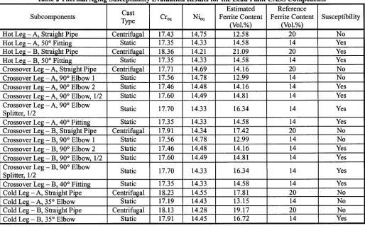
The potentially significant effect from thermal aging embrittlement may occur on CASS components. For the lead plant, RCS main loop pipe and elbow including some valve bodies were fabricated from A351 CF8M CASS. Thus, the values of ferrite contem described in CMTR and ~ estimated from chemical composition were compared with the corresponding allowable limits that are presented in EPRI reports and CCNPP license renewal application etc. Table 2 is a results of the thermal aging susceptibility evaluation for the CASS components of the lead plant. As shown in the table, some of the estimated ferrite contems exceed the allowable limits.
There are two methodologies to resolve this thermal aging issue. The one is to demonstrate the integrity through base metal inspection and the other is to perform fracture mechanics analyses using the methodology of NUREG/CR-4513 Rev.l[19]. In order to determine an optimum option from the two alternatives, at this time, plant specific consideration is being carried out. Additionally, some of the sample site measurements of ferrite content using Ferrite Scope devices were performed for confirmation of these values. These data can be also utilized in base metal inspection and/or fracture mechanics analyses to verify the integrity of the CASS components.
Table 2 Thermal Aging Susceptibility Evaluation Results for the Lead Plant CASS Components
Subcomponents Hot L e g - A, Straight Pipe Hot L e g - A, 50 ° Fitting Hot L e g - B, Straight Pipe Hot L e g - B, 50 ° Fitting
Crossover L e g - A, Straight Pipe Crossover L e g - A, 90 ° Elbow 1 Crossover L e g - A, 90 ° Elbow 2 Crossover L e g - A, 90 ° Elbow, 1/2 Crossover L e g - A, 90 ° Elbow Splitter, 1/2
Crossover L e g - A, 40 ° Fitting
Cast Type Centrifugal Static Centrifugal Static Centrifugal Static Static Static Static Static Creq 17.43 17.35 18.36 17.35 17.71 17.56 17.46 17.60 17.70 17.35 Nieq 14.75 14.33 14.21 14.33 14.69 14.78 14.48 14.49 14.33 14.33 Estimated Ferrite Content (Vol.%) Reference Ferrite Content (VoL%) Susceptibility
12.58 20 No
14.58 14 Yes
21.09 20 Yes
14.58 i 14 Yes
14.16 20 No
12.99 14 No
14.16 14 Yes
14.81 i 14 Yes
16.34 14 Yes
14.58 14 Yes
17.42 20 No
12.99 14 No
Crossover Leg Crossover Le~ Crossover Le8 Crossover Le8
B, Straight Pipe B, 90 ° Elbow 1 B, 90 ° Elbow 2 B, 90 ° Elbow, 1/2 Crossover L e g - B, 90 ° Elbow Splitter, 1/2
Crossover L e ~ - B, 40 ° Fitt Cold L e 8 - A, Straight Pipe Cold L e g - A, 35 ° Elbow Cold L e g - B, Straight Pipe Cold L e g - B, 35 ° Elbow
Fittin~ Centrifugal Static Static Static Static Static 17.91 Centrifugal Static 17.56 17.46 17.60 17.70 17.35 14.34 17.91 14.78 14.48 14.49 14.33 14.33 14.16 14.45 14.81 16.34 14.58 14 16.72 14 14 14 Yes Yes Yes Yes
Centrifugal 18.23 [ 14.55 17.81 20 No
Static 17.19 [ 14.43 13.15 14 No
|
18.13 i 14.28 19.17 20 No
14 ! Yes
SITE WALKDOWN
In order to demonstrate the overall integrity of Class 1 piping and associated components, two times site walkdown were performed during ISI periods(3rd ISI 1st interval and 2nd interval). These results can be incorporated in the activities to determine the integrated residual lives and to establish the efficient plan of aging management programs. However, there were no remarkable indications that can affect the integrity of Class 1 piping and associated components except some minor indications.
ONGOING ACTIVITIES AND LESSONS LEARNED
At this time, third party experts as well as site staffs are reviewing the detailed results that are briefly described in this paper. It is important to derive a consensus of Korean nuclear industry and can be incorporated in developing plant specific and objective programs for aging management of the lead plant. Also, a web-database construction is being carried out in order to control and refill the some lacks of information since the Korean lead plant is a turnkey type oldest vintage plant in Korea. After completion of these activities, the database that include both design and engineering data can be used to manage the specific aging effects regarding the lead plant efficiently.
CONCLUSIONS
technical point of view, the preliminary results gave the possibility as a prototype application and, at present, further efforts focused on establishing aging management programs and activities are being made to assure the safety and reliability of the lead plant beyond the design life.
REFERENCES
1. Hong, S.Y., Jeong, I.S. and Jin, T.E., "Recent Strategy and Progress in Korean Nuclear PLiM Program," Journal of Nuclear Engineering and Design, Vo1.174, 1997. Pp. 25~32.
2. Baltimore Gas and Electric, "Calvert Cliffs Nuclear Power Plant License Renewal Application," EPRI TR-111031, 1998. 3. Duke Energy, "Oconee Nuclear Station Application for Renewed Operating Licenses," EPRI TR-111030, 1998.
4. USNRC, "Standard Review Plan for the Review of License Renewal Applications for Nuclear Power Plants," Working Draft, 2000.
5. USNRC, "Generic Aging Lessons Learned(GALL)," NUREG/CR-6490, 2000.
6. Kim, J.S., Chang, Y.S., Jin, T.E. and Jeong, I.S., "Development Process of Aging Management Programs for Major SSCs of a PWR Plant", Proc. of the 12th Pacific Basin Nuclear Conference, Vol.2, pp. 1301~1308, Seoul, Korea, October 2000.
7. Tubeco, Welding Procedure WP8-8, 1973. 8. Tubeco, Welding Procedure WP8-1 Rev.1, 1973. 9. Tubeco, Welding Procedure WP8-18N Rev.2, 1973.
10. B&W Nuclear Technologies and Duke Power Company, "PWR Reactor Coolant System, License Renewal Industry Report," EPRI/TR-103844 Rev.1, 1994.
11. KOPEC and Westinghouse, "Aging Management Review for the Kori 1 Class 1 Piping,", Final Draft, 2001. 12. USA Standard Committee, B31.1 Code for Pressure Piping, 1967.
13. Structural Integrity Associates, Inc., "Fatigue Comparison of Piping Designed to ANSI B31.1 and ASME Section I I I - Class 1 Rules,", EPRI/TR- 102901, 1993.
14. Westinghouse, "Structural Analysis of Reactor Coolant Loop/Support System for Ko-ri Nuclear Power Plant Unit No.l," 1974.
15. KEPCO, "Kori Unit 1 Replacement Steam Generator Safety Analysis Report," 1996.
16. Westinghouse, "Structural Analysis of the Reactor Coolant Loop Piping for Kori Unit 2 Nuclear Power Plant," WCAP- 10253, Vol.1, 1973.
17. Westinghouse, "ASME Section III Class 1 Reactor Coolant Loop Branch Nozzle Stress Analysis for the Kori Unit 2 Nuclear Power Plant," WCAP- 10190, 1983.
18. Westinghouse, "ASME Section III Class 1 Auxiliary Piping Stress Analysis for the Kori Unit 2 Nuclear Power Plant," WCAP- 10189, 1983.
19. Chopra, O.K., "Estimation of Fracture Toughness of Cast Stainless Steels During Thermal Aging in LWR Systems," NUREG/CR-4513, Rev. 1, 1994.