UNIVERSITI TEKNIKAL MALAYSIA MELAKA
SMART BICYCLE SAFETY SYSTEM
This report submitted in accordance with requirement of the Universiti Teknikal Malaysia Melaka (UTeM) for the Bachelor’s Degree in Computer Engineering
Technology
(Computer Systems) with Honours
by
MUHAMMAD HILMI BIN MOHD YUSOFF B071310807
910518-08-6287
BORANG PENGESAHAN STATUS LAPORAN PROJEK SARJANA MUDA
SULIT
TERHAD
TIDAK TERHAD
UNIVERSITI TEKNIKAL MALAYSIA MELAKA
(Mengandungi maklumat yang berdarjah keselamatan atau kepentingan Malaysia sebagaimana yang termaktub dalam AKTA RAHSIA RASMI 1972)
Alamat Tetap:
No.44, Pt 76301
Kampung Tersusun Batu 8,
31150, Ulu Kinta. Perak
Tarikh: ________________________
(Mengandungi maklumat TERHAD yang telah ditentukan oleh organisasi/badan di mana penyelidikan dijalankan)
Disahkan oleh:
Cop Rasmi:
** Jika Laporan PSM ini SULIT atau TERHAD, sila lampirkan surat daripada pihak berkuasa/organisasi berkenaan dengan menyatakan sekali sebab dan tempoh laporan PSM ini perlu dikelaskan sebagai SULIT atau TERHAD.
TAJUK: Smart Bicycle Safety System
SESI PENGAJIAN: 2016/17 Semester 1
Saya MUHAMMAD HILMI BIN MOHD YUSOFF
mengaku membenarkan Laporan PSM ini disimpan di Perpustakaan Universiti Teknikal Malaysia Melaka (UTeM) dengan syarat-syarat kegunaan seperti berikut:
1. Laporan PSM adalah hak milik Universiti Teknikal Malaysia Melaka dan penulis. 2. Perpustakaan Universiti Teknikal Malaysia Melaka dibenarkan membuat salinan
untuk tujuan pengajian sahaja dengan izin penulis.
3. Perpustakaan dibenarkan membuat salinan laporan PSM ini sebagai bahan pertukaran antara institusi pengajian tinggi.
I hereby, declared this report entitled “Smart Bicycle Safety System” is the results of my own research except as cited in references.
Signature : ...
Author’s Name : Muhammad Hilmi Bin Mohd Yusoff
This report is submitted to the Faculty of Engineering Technology of UTeM as a partial fulfillment of the requirements for the degree of Bachelor’s in Computer Engineering Technology (Computer Systems) (Hons.). The members of the supervisory committee are as follow:
……… HASRUL ‘ NISHAM BIN ROSLY
(Principal Supervisor)
……… ROSZIANA BINTI HASHIM
i
ABSTRAK
ii
ABSTRACT
iii Every challenging work needs self efforts as well as guidance of elders, especially those
who were very close to our heart.
My humble effort I dedicate to my sweet and loving
Father & Mother,
Whose affection, love, encouragement and prayers of day and night make me able to get such success and honor,
Along with all hardworking and respected
Lecturers
iv This project praises to the Almighty God for giving me the grace, courage and strength to complete it. I am very thankful to my parents for their love, support and encouragement and for being with me on each and every step of my life. I am also very thankful to my father Mohd Yusoff Bin Abdullah for being very supporting and motivating.
I wish to express my deepest appreciation to my supervisor, Mr. Hasrul ‘ Nisham Bin Rosly for his idea, guidance, motivation and help throughout my project, Smart Bicycle Safety System using Arduino System which is part of the Final Year Project required for Bachelor’s Degree in Computer Engineering Technology (Computer ystems) with Honours. I feel thankful to him for his insightful advice and suggestions. Without his support and guidance, it is impossible for me to complete my project successfully. Special thanks also to my co-supervisor, Mrs. Rosziana Binti Hashim for their constructive criticisms and guidance which helped me in achieving better project development.
I am also thankful to Puan Siti Haryanti Binti Hairol Anuar my academic advisor for giving me a generous amount of time whenever I needed some help. In particular, I am thankful to Ahmad Zuhair Bin Umairah , Mohd Amin Bin Manan, Fazrin Bin Semi and Mohd Hami Hamizan Bin Mohd Hilmi whom helped me during this project, cooperative and learnt a lot. I would like to extend my appreciation to my family and all members. They have always been there to support and encourage me unconditionally. Last but not least, I would like to thank all my lecturers who taught me throughout my education at Universiti Teknikal Malaysia Melaka.
v
TABLE OF CONTENT
Abstrak i
Abstract ii
Dedication iii
Acknowledgement iv
Table of Content v
List of Table viii
List of Figure ix
List Abbreviations, Symbols and Nomenclatures xi
CHAPTER 1: INTRODUCTION 1
1.1 Project Background 1
1.2 Project Problem Statements 2
1.3 Project Objectives 3
1.4 Project Scope and Limitations 3
1.5 Project Significance 4
1.6 Summary 5
CHAPTER 2: LITERATURE REVIEW 6
2.0 Introduction 6
2.1 System Hardware 6
2.1.1 Arduino Uno 7
2.1.2 Arduino UNO and Raspberry Pi 11
2.1.3 LED Dot Matrix 12
vi
2.1.5 Battery (Power Bank) 14
2.1.6 Micro Touch Switch YD-024 15
2.1.7 Arduino Current Sensor 16
2.1.8 5V Arduino IIC/12C 1602 16x2 LCD Blue/White 17
2.2 Previous Research 18
2.2.1 Harnessing Ocean Wave Energy to Generate Electricity 18 2.2.2 Mini Electric Scooter (Rechargeable Battery Using Dynamo) 19
2.2.3 Dynamo Charging Phone 20
2.2.4 Mechanically Powered Battery Charger for LED Lighting 21
2.3 Summary 22
CHAPTER 3: METHODOLOGY 23
3.1 Project Development Process 23
3.1.1 Requirement Analysis 24
3.1.2 System Design 25
3.1.3 Implementation 25
3.1.4 Testing 25
3.1.5 Maintenance 25
3.2 Project of Flowchart 26
3.3 The Architecture of System 28
3.4 Hardware Design 29
3.5 Summary 31
CHAPTER 4: RESULT AND DISCUSSION 32
4.1 Introduction 32
4.2 Development Phase 33
vii 4.3.1 Arduino UNO and I2C LCD Modules 16x2 34 4.3.2 Arduino UNO and ACS712 Current Sensor Module 35
4.3.3 Arduino UNO and LED Dot Matrix 8x8 36
4.3.4 Arduino UNO and Micro Touch Switch YD-024 37
4.3.5 Complete Hardware Setup 38
4.4 Software Implementation 39
4.5 Testing and Results 43
4.5.1 Testing Phase 1 (Finding Current) 43
4.5.2 Testing Phase 2 (Charging Power bank) 44
4.6 Discussion 45
4.6.1 Limitation of Study 46
4.6.2 Problems Encountered 46
CHAPTER 5: CONCLUSION AND RECOMMENDATION 47
5.1 Introduction 47
5.2 Conclusion 47
5.3 Recommendation 48
5.4 Commercialization Potential 49
5.5 Future Work 49
REFERENCE 50
APPENDICES 53
A Coding For Smart Bicycle Safety System 53 B Schematic Diagram For Arduino Uno REV3 57
viii LIST OF TABLES
2.1 Function of Each Power Pin 9
2.2 Function of Each Pin 10
2.3 Comparison between Arduino UNO and Raspberry Pi 11 4.1 Connection of Arduino UNO and I2C LCD Modules 16x2 34 4.2 Connection of Arduino UNO and LED Dot Matrix 8x8 36
4.3 Result of Current When Speed Is Increasing 43
ix LIST OF FIGURE
1.1 Block Diagram 4
2.1 Arduino Uno 8
2.2 LED Dot Matrix 12
2.3 Dynamo Bicycle 13
2.4 Battery (Power Bank) 14
2.5 Micro Touch Switch YD-024 15
2.6 Arduino Current Sensor 16
2.7 5V Arduino IIC/12C 1602 16x2 LCD Blue/White 17
2.8 Fundamental concept of a buoy/cable reel wave energy harnessing system 19
2.9 Dynamo Charging Phone 21
2.10 Mechanically Powered Battery Charger for LED Lighting 22
3.1 Waterfall Model 24
3.2 Project Flow Chart 26
3.3 Flow Chart of the System 27
3.4 The Overall Project Architecture 28
3.5 Project Block Diagram 29
4.1 Connection of Arduino UNO and I2C LCD Modules 16x2 34 4.2 Connection of Arduino UNO and ACS712 Current Sensor Module 35 4.3 Connection of Arduino UNO and LED Dot Matrix 8x8 36 4.4 Connection of Arduino UNO and Micro Touch Switch YD-024 37
4.5 Hardware Setup 38
x
4.7 LED Display 39
4.8 Setting For Current Sensor 40
4.9 Current Formula Code 41
4.10 LCD Code and Display 42
4.11 Graph of Current Vs Speed 44
xi
LIST OF ABBREVATIONS, SYMBOLS AND
NOMENCLATURES
A - Ampere
AC - Alternating Current
AuC - Authentication Centre
BSC - Base Station Controller
BSS - Base Station Subsystem
BTS - Base Transceiver
Station
CEPT - European Conference
of Postal and
Telecommunications
DC - Direct Current
DTMF - Dual Tone Multi
Frequency
EIR - Equipment Identity
Register
ETSI - European
Telecommunications Standards
GMSC - Gateway Mobile
Switching Centre
GPIO - General Purpose Input
Output
xii Service
GSM - Global System for
Mobile Communication
HD - High Definition
HDMI - High Definition
Multimedia Interface
HLR - Home Location
Register
ME - Mobile Equipment
MMS - Multimedia Messaging
Service
MOD - Module
MoU - Memorandum of
Understanding
MS - Mobile Station
MSC - Mobile Switching
Centre
NOOBS - New Out Of the Box
1
Chapter 1
INTRODUCTION
This chapter explains the introduction of the project, problem statements, the objectives of the project being done, scope of the project, project significant and also the conclusion of the introduction part.
1.1 Project Background
The common motorist views bicyclists as unpredictable on city streets and often lack experience sharing the road with motorists. The key to integrating bicyclists and motor vehicles on the same road with both parties feeling comfortable around one another lies in a common means of communication. Now that darkness appears quicker, and the night is especially dangerous for cyclists because of the low visibility that drivers have. Bicycles lack a signaling system based on lights, like that of a motor vehicle, which other motorists easily read and interpret. Not only is darkness a danger, but also fog, blizzards, and heavy rain all wreaking havoc on the vision. To combat this, bikers attach reflectors: clear front reflectors, red rear reflectors, amber pedal reflectors, and clear side reflectors; some even add reflectors to their clothing.
2 According to the League of American Bicyclists, in 2007, 698 cyclists sustained fatal injuries, and 43,000 cyclists received injuries in accidents involving motor vehicles . The Bureau of Transportation Statistics held a survey asking cyclists how safe they felt. Only 50% of the cyclists felt safe, while less than a quarter of the overall responses felt completely safe while bicycling . Misunderstandings between cyclists and motorists, as well as an unawareness of cyclists by motorists, account for the largest causes of accidents. This project aims to increase the safety of both cyclists and motor vehicles and lower the number of bicyclists injured or killed while riding. To accomplish this, the project implements turn signal indicators and brake lights on bicycles, similar to those found on motor vehicles.
3 The main objectives of this project are:
I. To study Arduino system and motor that will be used in this system
II. To develop and estimated current that been produce when bicycle wheel are moving
III. To design a new safety in bicycle to enhances the functionality of Arduino system
1.4 Project Scope and Limitations
The work scope of this project is to estimated current that been produce when bicycle wheel are moving. A small dynamo (generator) mounted on the rear wheel produces a tiny current of electricity that keeps your back safety lamp lit in the dark. Now suppose it could run this process backward. What if the lamp is removed and be replaced with a large battery. The battery would kick out a steady electric current, driving the dynamo in reverse so that it spin around like an electric motor. As the dynamo/motor turned, it would rotate the tire and make the bike go along without any help from your pedaling.
Bikers will also increase their safeties when they ride their bicycle. This project can be divided into several part which is firstly, identify the software and hardware that will be used in this project.
4 Figure 1.1 Operation system with Arduino Microcontroller.
1.5 Project Significance
Everyone has to share the road whether people biking or driving, The goal for everyone is to get where people going in one piece. This project brings a little technology to your two-wheeler and adds brake lights and turn signals to each handlebar so drivers or other bikers always know when cyclist slowing or about to turn.
This project is a bit like some other similar projects, especially in that the turn signals and brake lights are powered by an Arduino. The best thing about this though is that the signals and the controls are built right into the handlebars and are completely waterproofed, so user don't have to worry about them failing on when user need them.
Switch Arduino
Microcontroller
Current Sensor Battery (Power bank)
LED Display Dynamo Bicycle
6
CHAPTER 2
LITERATURE REVIEW
2.0 Introduction
In this chapter, in order to make this project successful, some studies and researching has been done. The information and studies for this project was collected from many sources such as books, articles, journals and internet. All this information was used in this project as a guide to make sure this project can be done in the time given. All the studies and information collected was based on major component and topic that related to this project.
2.1 System Hardware
7 Arduino is a software company, project, and user community that designs and manufactures computer open-source hardware, open-source software, and microcontroller-based kits for building digital devices and interactive objects that can sense and control physical devices. The project is based on microcontroller board designs, produced by several vendors, using various microcontrollers. These systems provide sets of digital and analog I/O pins that can interface to various expansion boards (termed shields) and other circuits. The boards feature serial communication interfaces, including Universal Serial Bus (USB) on some models, for loading programs from personal computers.
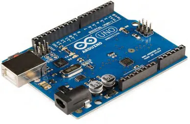
8 Figure 2.1 Arduino Uno (Aaron, 2013)
The Arduino UNO is a microcontroller board based on the ATmega328. It has 14 digital pin input and output of which 6 can be used as PWM outputs, 6 analog inputs, a 16 MHz ceramic resonator, a USB connection, a power jack, ICSP header and a reset button. It contains everything needed to support the microcontroller.