University of Southampton Research Repository
ePrints Soton
Copyright © and Moral Rights for this thesis are retained by the author and/or other
copyright owners. A copy can be downloaded for personal non-commercial
research or study, without prior permission or charge. This thesis cannot be
reproduced or quoted extensively from without first obtaining permission in writing
from the copyright holder/s. The content must not be changed in any way or sold
commercially in any format or medium without the formal permission of the
copyright holders.
When referring to this work, full bibliographic details including the author, title,
awarding institution and date of the thesis must be given e.g.
UNIVERSITY OF SOUTHAMPTON
FACULTY OF ENGINEERING, SCIENCE AND MATHMATICS
INSTITUTE OF SOUND AND VIBRATION RESEARCH
ACTIVE VIBRATION ISOLATION WITH A
DISTRIBUTED PARAMETER ISOLATOR
by
Bo Yan
Thesis submitted for the degree of Doctor of Philosophy
UNIVERSITY OF SOUTHAMPTON
ABSTRACT
FACULTY OF ENGINEERING, SCIENCE AND MATHMATICS INSTITUTE OF SOUND AND VIBRATION RESEARCH
DOCTOR OF PHILOSOPHY
Active Vibration Isolation with a Distributed Parameter Isolator
by Bo Yan
Conventional vibration isolators are usually assumed to be massless for the purpose of modelling. This simplification tends to overestimate the isolator performance because of neglecting the internal resonances (IRs) due to the distributed mass effects in the isolator, which is especially important for lightly damped metallic isolators. Previous research on the problem of IRs is not particularly comprehensive, because it does not clarify the characteristics of the distributed parameter isolator. Furthermore, with the development of active vibration isolation, there is a need to investigate the effects of isolator IRs on the control performance and stability for commonly used control strategies. Effective ways to attenuate these effects are also required.
This thesis concerns the active vibration isolation of a piece of delicate equipment mounted on a distributed parameter isolator, which is modelled as different idealised configurations under various types of deformation. The model is first developed to determine the effects of IRs on a single-degree-of-freedom system with a distributed parameter isolator. This analysis is then extended to include the resonance behaviour of the supporting structure. Simple expressions are derived which describe the behaviour of various types of distributed parameter isolator. The parameters which control the isolator performance at various frequencies are clarified theoretically and experimentally. The effects of IRs on control performance and stability of several control strategies are determined and compared. Absolute Velocity Feedback (AVF) control is shown to be the optimal solution to minimise the mean square velocity of the equipment mass supported by a distributed parameter isolator.A stability condition for an AVF control system containing a distributed parameter isolator is proposed. Based on this condition, different approaches to stabilize such a control system are presented. Experimental work is carried out to validate the theoretical results.
Acknowledgements
I would like to express my most sincere gratitude to my supervisors, Prof. Mike Brennan, Prof. Steve Elliott and Dr. Neil Ferguson, not only for their numerous guidance, constant support and kind encouragement throughout this research, but also for their precious advice which is invaluable for my future development.
Many constructive suggestions from Prof. Paolo Gardonio and Prof. Brian Mace to improve the quality of this work are gratefully acknowledged.
Many thanks also go to Mrs. Maureen Mew, Miss Anne-Marie McDonnell, Miss Joanne Hazell and other ISVR administrative stuff for their kind assistance and care during my study; to the workshop technicians for their effective assistance in my experimental work; to my friends and colleagues in the ISVR for their constant support and generous friendship; and to those I cannot all mention here, whose kindness and help makes my life in the UK more enjoyable.
Contents
Abstract...i
Acknowledgements...ii
Contents ...iii
List of Figures ...viii
List of Tables...xxiii
Nomenclature...xxiv
1. Introduction ... 1
1.1 Background ...1
1.1.1 Vibration control ...1
1.1.2 Vibration isolation...3
1.1.2.1 Passive vibration isolation ...4
1.1.2.2 Active vibration isolation...6
1.1.3 Internal resonances in vibration isolators...10
1.1.3.1 Introduction ...10
1.1.3.2 Distributed parameter isolator models ... 11
1.1.3.3 IRs in different types of isolators ...12
1.1.3.4 Control of IRs...13
1.2 Motivation and objectives of the thesis...14
1.3 Contributions of the thesis ...16
1.4 Overview of the thesis...17
2. Review of Active Vibration Isolation with a Massless Isolator ... 20
2.1 Introduction ...20
2.2 Passive vibration isolation with a massless isolator...21
2.3 Introduction to single channel feedback control ...22
2.4 Active vibration isolation with a massless isolator ...24
2.4.1 Absolute Velocity Feedback (AVF) control ...24
2.4.1.1 Control performance ...24
2.4.1.2 Stability analysis ...25
2.4.2 Relative Velocity Feedback (RVF) control ...26
2.4.2.1 Control performance ...26
2.4.2.2 Stability analysis ...27
2.4.3 Integral Force Feedback (IFF) control ...28
Contents
2.4.4 Positive Position Feedback (PPF) control...30
2.4.4.1 Control performance ...31
2.4.4.2 Stability analysis ...32
2.4.5 Acceleration-Position Feedback (APF) control ...33
2.4.5.1 Control performance ...34
2.4.5.2 Stability analysis ...35
2.4.6 Comparison of the control performance ...36
2.4.7 Acceleration feedback control...37
2.4.7.1 Control performance ...37
2.4.7.2 Stability analysis ...38
2.4.8 Optimal control ...38
2.4.9 Summary ...41
2.5 Conclusions ...42
3. Passive Vibration Isolation with a Distributed Parameter Isolator ... 49
3.1 Introduction ...49
3.2 System undergoing base motion ...50
3.2.1 Theoretical analysis...50
3.2.1.1 Non-dispersive isolator ...51
3.2.1.2 Dispersive isolator...57
3.2.1.3 Summary ...61
3.2.2 Experimental validation on a helical spring...62
3.2.2.1 Experimental setup...62
3.2.2.2 Experimental validation ...62
3.3 System on a flexible base...64
3.4 Conclusions ...68
4. Active Vibration Isolation with a Distributed Parameter Isolator ... 75
4.1 Introduction ...75
4.2 System undergoing base motion ...76
4.2.1 Absolute Velocity Feedback (AVF) control ...76
4.2.1.1 Control performance ...76
4.2.1.2 Stability analysis ...79
4.2.2 Relative Velocity Feedback (RVF) control ...79
4.2.2.1 Control performance ...80
4.2.2.2 Stability analysis ...83
4.2.3 Integral Force Feedback (IFF) control ...83
4.2.3.1 Control performance ...83
4.2.3.2 Stability analysis ...84
4.2.4 Positive Position Feedback (PPF) control...85
4.2.4.1 Control performance ...85
Contents
4.2.5 Acceleration-Position Feedback (APF) control ...88
4.2.5.1 Control performance ...88
4.2.5.2 Stability analysis ...89
4.2.6 Comparison of the control performance ...90
4.2.7 Acceleration feedback control...90
4.2.7.1 Control performance ...91
4.2.7.2 Stability analysis ...91
4.2.8 Optimal control ...92
4.2.9 Summary ...94
4.3 System on a flexible base...95
4.3.1 Absolute Velocity Feedback (AVF) control ...95
4.3.1.1 Control performance ...95
4.3.1.2 Stability analysis ...97
4.3.2 Relative Velocity Feedback (RVF) control ...99
4.3.2.1 Control performance ...100
4.3.2.2 Stability analysis ...101
4.3.3 Integral Force Feedback (IFF) control ...102
4.3.3.1 Control performance ...102
4.3.3.2 Stability analysis ...102
4.3.4 Positive Position Feedback (PPF) control...103
4.3.4.1 Control performance ...103
4.3.4.2 Stability analysis ...104
4.3.5 Acceleration-Position Feedback (APF) control ...105
4.3.5.1 Control performance ...105
4.3.5.2 Stability analysis ...106
4.3.6 Comparison of control performance ...107
4.3.7 Acceleration feedback control...108
4.3.7.1 Control performance ...108
4.3.7.2 Stability analysis ...109
4.3.8 Summary ...109
4.4 Conclusions ... 110
5. AVF Control on a System Containing a Distributed Parameter Isolator ... 125
5.1 Introduction ...125
5.2 Approaches to stabilize the AVF control system...126
5.2.1 Adding more damping in the isolator...126
5.2.2 Adding more mass to the base ...127
5.2.3 Electronic means: introducing a lead compensator...128
5.2.4 Mechanical means ...129
5.3 Experimental validation for AVF control system...133
5.3.1 Experimental setup...134
5.3.2 Passive response...135
Contents
5.3.4 Control performance ...139
5.3.5 Approaches to stabilize the AVF control system...140
5.3.5.1 Adding more mass to the base ...140
5.3.5.2 Electronic means: introducing a lead compensator...141
5.4 Conclusions ...143
6. Control of Internal Resonances ... 168
6.1 Introduction ...168
6.2 AVF control with more damping in the isolator...169
6.3 Absolute velocity plus acceleration feedback control...170
6.3.1 System undergoing base motion ...171
6.3.1.1 Control performance ...171
6.3.1.2 Stability analysis ...173
6.3.2 System on a flexible base...174
6.3.2.1 Control performance ...174
6.3.2.2 Stability analysis ...175
6.3.3 Limitations in practice...178
6.4 AVF control on a fraction of the isolator length ...178
6.4.1 System undergoing base motion ...179
6.4.1.1 Control performance ...179
6.4.1.2 Stability analysis ...186
6.4.2 System on a flexible base...186
6.4.2.1 Control performance ...186
6.4.2.2 Stability analysis ...189
6.4.3 Limitations in practice...191
6.5 Conclusions ...192
7. Control of Internal Resonances: Experimental Validation ... 204
7.1 Introduction ...204
7.2 Experimental validation for AVF control with additional damping in the isolator...205
7.2.1 Stability analysis ...205
7.2.2 Control performance ...207
7.2.3 Summary ...208
7.3 Experimental validation for absolute velocity plus acceleration feedback control ...209
7.3.1 Experimental setup...209
7.3.2 Stability analysis ...210
7.4 Conclusions ...212
Contents
8.1 Conclusions ...220
8.2 Recommendations for further work ...224
References ... 225
Appendix A: Impedance Matrices for Distributed Parameter Isolators ... 234
A.1 Impedance matrix for a non-dispersive isolator...234
A.2 Impedance matrix for a dispersive isolator ...239
Appendix B: Characteristics of a Helical Spring ... 242
B.1 Static stiffness ...242
B.2 Internal resonances...244
Appendix C: Dynamic Analysis of a System Containing a Distributed Parameter Isolator... 246
C.1 Impedances at the equipment and the base ...246
List of Figures
1.1 Schematic diagram of a general vibration control problem....19
1.2 Schematic diagram of a traditional passive vibration isolation model....19
1.3 Transmissibility of the traditional SDOF passive isolation model with different
damping in the isolator....19
1.4 Schematic diagram of a traditional active vibration isolation model....19
2.1 Schematic diagram of a vibration isolation system containing a massless isolator
undergoing base motion, where u&e and b
u& are velocities of the equipment and the
base respectively; Z is the input impedance of the unconnected equipment at the e location of the isolator connection; k is the spring stiffness and c is the damping
coefficient of the viscous damper....43
2.2 Schematic diagram of a single channel feedback control system....43
2.3 Equivalent block diagram of the single channel feedback control system shown in
Figure 2.2....43
2.4 (a) schematic diagram and (b) mechanical representation of a base excited system
containing a massless isolator under AVF control, where h is the constant feedback
control gain and f is the active control force.a ...44
2.5 Transmissibility of the active vibration isolation system under AVF control with
0.005
ζ = and the active damping ratio
ζ
a =0 (solid line),ζ
a =0.1 (dashed line) orζ
a =0.5 (dotted line).... 442.7 Schematic diagram of a base excited system containing a massless isolator under
IFF control, where HIFF
(
jω)
is the frequency response of the IFF controller and Tf is the transmitted force to the equipment.... 45
2.8 Schematic diagram of a base excited system containing a massless isolator under
PPF control, where u is the displacement of the equipment and e HPPF
(
jω)
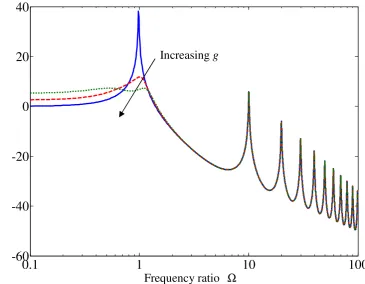
is the frequency response of the PPF controller.... 452.9 Frequency response of the PPF controller when the natural frequency of the filter
5 f
ω = , the damping ratio of the filter ζf =0.5 and the gain g =0.5.... 45
2.10 Transmissibility of the active vibration isolation system under PPF control when
0.005
List of Figures (solid line), g=0.5 (dashed line) or g =0.9(dotted line).... 46
2.11 Schematic diagram of a base excited system containing a massless isolator under
APF control, where u&&e is the acceleration of the equipment and
(
)
APFH jω is the frequency response of the APF controller.... 46
2.12 Transmissibility of the active vibration isolation system under APF control with
0.005
ζ = , ωf =ωe, ζf =0.5 and ζa =0 (solid line), ζa =0.1 (dashed line) or 0.5
a
ζ = (dotted line).... 47
2.13 Normalized change in mean square velocity for the system under AVF (solid line), RVF (dashed line), IFF (dotted line), PPF (line with circle) and APF
(dashed-dotted line) control compared to the passive system when ζ =0.005, 0.5
e
m = , ωf =ωe and ζf =0.5.... 47
2.14 (a) schematic diagram and (b) mechanical representation of a base excited system
containing a massless isolator under acceleration feedback control.... 48
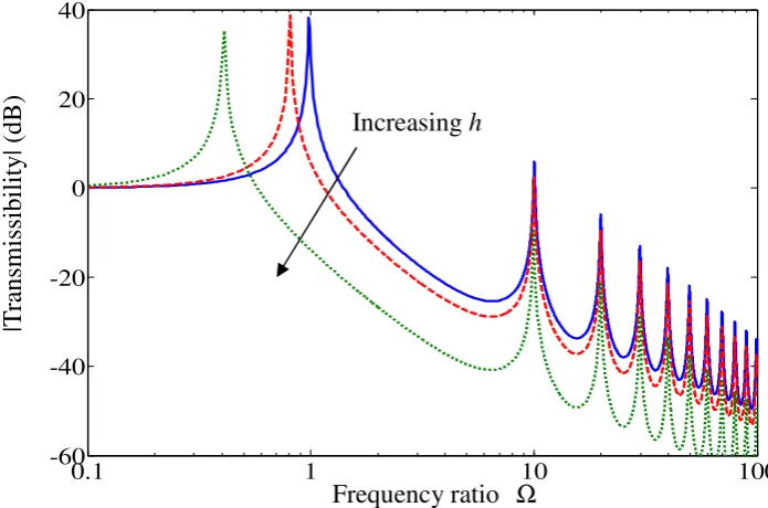
2.15 Transmissibility of the vibration isolation system under acceleration feedback
control when ζ =0.005 and h=0 (solid line), h me=0.5 (dashed line) or 5
e
h m = (dotted line).... 48
2.16 Schematic diagram of a base excited system containing a massless isolator under
optimal control.... 48
3.1 Schematic diagrams of passive vibration isolation systems containing a distributed
parameter isolator under (a) longitudinal, (c) torsional or (e) lateral vibration. (b),
(d) and (f) are respectively free body diagrams. Q , e Q and 1 Q are the internal 2 forces in (b) and (f), or moments in (d); u&e and u&b are velocities in (b) and (f), or angular velocities (d) of the equipment and the base respectively; Z is the input e impedance of the equipment; ZL and ZT are the impedance matrices for the rod
under longitudinal and torsional vibration, respectively; and ZS and ZB are the
impedance matrices for the shear beam and Euler-Bernoulli beam, respectively.70
3.2 Transmissibility of the passive vibration isolation systems with a non-dispersive isolator when the ratio of the mass of the isolator to the mass of the equipment
0.1 i
µ = , and the loss factor in the isolator ηi =0.01 (solid line). The dashed line passes through the IR peaks. The dotted line passes through the troughs in the
List of Figures circled is the intersection of the transmissibilities for the system with a massless
isolator and for the system with a non-dispersive isolator.... 71
3.3 Mechanical representation of the Thevenin equivalent system for the passive
vibration isolation systems shown in Figure 3.1, where Z21 and Z22 are
respectively the transfer and point impedances of the isolator and f is the B blocked force.... 71
3.4 Transmissibility of the passive vibration isolation system with a dispersive isolator when µi =0.1 and ηi =0.01 (solid line). The dashed line passes through the IR peaks. The dotted line passes through the troughs in the transmissibility. The
dashed-dotted line is for the massless isolator. The point circled is the intersection
of the transmissibilities for the system with a massless isolator and for the system
with a dispersive isolator.... 72
3.5 (a) photograph and (b) schematic diagram of the experimental rig of a mass
supported by a helical spring undergoing base motion.... 72
3.6 Measured (solid bold) and predicted (solid faint) transmissibility of the experimental rig. The dashed line passes through the IR peaks. The dotted line
passes through the troughs in the transmissibility. The dashed-dotted line is for the
massless isolator. The point circled is the intersection of the transmissibilities for
the system with a massless isolator and for the system with a distributed parameter
isolator.... 73
3.7 (a) schematic diagram and (b) free body diagram of the passive vibration isolation system containing a distributed parameter isolator on a flexible base, where f is
the primary force applied to the base, Q is an internal force and b Z is the input b impedance of the base.... 73
3.8 Amplitude ratio of the passive vibration isolation system shown in Figure 3.7 when
0.1 i
µ = , ηi =0.01, the ratio of the mass of the base to the mass of the equipment 0.1
b
µ = , the ratio of the static stiffness of the isolator to the stiffness of the base 0.01
k
µ = and the loss factor in the base ηb =0.01 (solid line). The dashed line passes through the IR peaks. The dotted line passes through the troughs in the
amplitude ratio. The dashed-dotted line is for the massless isolator. The point
List of Figures isolator and for the system with a distributed parameter isolator.... 74
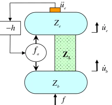
4.1 (a) schematic diagram and (b) free body diagram of base excited active vibration
isolation system containing a distributed parameter isolator under AVF control,
where u&e and u&b are velocities of the equipment and the base respectively; Z is e the input impedance of the unconnected equipment at the location of the isolator
connection; ZL is the impedance matrix of the isolator; h is the constant feedback
control gain; f is the active control force; and a Q , e Q and 1 Q are internal 2
forces.... 111
4.2 Mechanical representation of the base excited active vibration isolation system
containing a distributed parameter isolator under AVF control.... 111
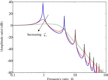
4.3 Transmissibility of the active vibration isolation system under AVF control when the ratio of the mass of the isolator to the mass of the equipment µi =0.1, the loss factor in the isolator ηi =0.01, and the active damping ratio ζa =0 (solid line),
0.2 a
ζ = (dashed line) or ζa =1 (dotted line). The bold and faint dashed-dotted lines pass through the IR peaks and the troughs of the transmissibility respectively.
... 112
4.4 Mechanical representation of the Thevenin equivalent system for the active
vibration isolation system under AVF control shown in Figure 4.1, where Z and 21
22
Z are respectively the transfer and point impedances of the isolator, and f is B the blocked force.... 112
4.5 (a) schematic diagram and (b) mechanical representation of base excited active
vibration isolation system containing a distributed parameter isolator under RVF
control.... 113
4.6 Transmissibility of the active vibration isolation system under RVF control when 0.1
i
µ =
,
ηi =0.01, and ζa =0 (dashed line) or ζa =1 (solid line). The two dashed-dotted lines pass through the IR peaks and the dotted line passes throughthe troughs of the transmissibility.... 113
4.7 Mechanical representation of the Thevenin equivalent system for the active
vibration isolation system under AVF control shown in Figure 4.5.... 114
4.8 Schematic diagram of base excited active vibration isolation system containing a
List of Figures frequency response of the IFF controller and f is the transmitted force to the T equipment.... 114
4.9 Schematic diagram of base excited active vibration isolation system containing a
distributed parameter isolator under PPF control, where u is the displacement of e the equipment and HPPF
(
jω)
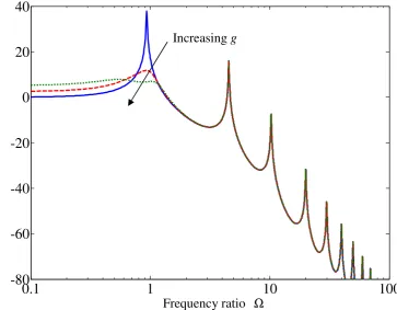
is the frequency response of the PPF controller.1144.10 Transmissibility of the active vibration isolation system under PPF control when
0.1 i
µ =
,
ηi =0.01, the natural frequency of the filter ωf =ωe, the damping ratio of the filter ζf =0.5, the mass of the equipment me=2 and the constant gain0
g = (solid line), g =0.5 (dashed line) or g=0.9(dotted line).... 115
4.11 Schematic diagram of base excited active vibration isolation system containing a
distributed parameter isolator under APF control, where u&&e is the acceleration of the equipment and HAPF
(
jω)
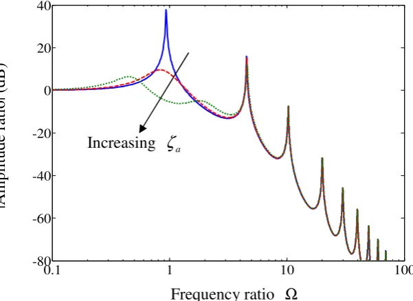
is the frequency response of the APF controller.1154.12 Transmissibility of the active vibration isolation system under APF control when
0.1 i
µ =
,
ηi =0.01 , ωf =ωe , ζf =0.5 and ζa =0 (solid line), ζa =0.2 (dashed line) or ζa =1 (dotted line).... 1164.13 Normalized change in mean square velocity for the base motion system under AVF (solid line), RVF (dashed line), IFF (dotted line), PPF (line with circle) and APF
(dashed-dotted line) control compared to the passive system when µi =0.1, 0.01
i
η = , me =0.5, ωf =ωe and ζf =0.5.... 116
4.14 (a) schematic diagram and (b) mechanical representation of a base excited system
containing a distributed parameter isolator under acceleration feedback control.
... 117
4.15 Transmissibility of the active vibration isolation system under acceleration feedback
control when µi =0.1
,
ηi =0.01 and h=0 (solid line), h me =0.5 (dashed line) or h me =5 (dotted line).... 1174.16 Schematic diagram of a base excited system containing a distributed parameter
isolator under optimal control, where u&l is the velocity of the middle mass.... 117
4.17 (a) schematic diagram and (b) free body diagram of an active vibration isolation
system containing a distributed parameter isolator on a flexible base under AVF
List of Figures
4.18 Amplitude ratio of the active vibration isolation system on a flexible base under
AVF control when µi =0.1, ηi =0.01, the ratio of the mass of the base to the mass of the equipment µb =0.5, the ratio of the static stiffness of the isolator to the stiffness of the base µk =0.1, the loss factor in the base ηb =0.01 and ζa =0 (solid line), ζa =0.2 (dashed line) or ζa =1 (dotted line).... 118
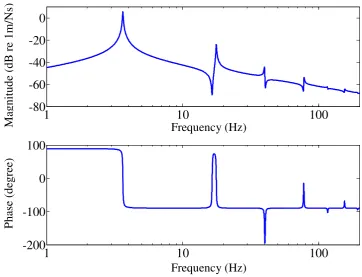
4.19 Plant responses of the AVF control system containing a distributed parameter
isolator on a flexible base when µi =0.1, µb =0.5, µk =0.1, and ηi =ηb =0.01. ... 119
4.20 Zoomed Nyquist plot of the plant responses of the AVF control system containing a
distributed parameter isolator on a flexible base whenµi =0.1, µb =0.5, µk =0.1 and ηi =ηb =0.01.... 119
4.21 Schematic diagram of an active vibration isolation system containing a distributed
parameter isolator on a flexible base under RVF control.... 120
4.22 Amplitude ratio of the active vibration isolation system on a flexible base under
RVF control when µi =0.1, µb =0.5 , µk =0.1 , ηi =ηb =0.01 and ζa =0 (solid line), ζa =0.2 (dashed line) or ζa =1 (dotted line).... 120
4.23 Schematic diagram of an active vibration isolation system containing a distributed
parameter isolator on a flexible base under IFF control.... 121
4.24 Schematic diagram of an active vibration isolation system containing a distributed
parameter isolator on a flexible base under PPF control.... 121
4.25 Amplitude ratio of the active vibration isolation system on a flexible base under
PPF control when µi =0.1 , µb =0.5 , µk =0.1 , ηi =ηb =0.01 , ωf =ωe , 0.5
f
ζ = , me =2 and g =0 (solid line), g=0.5(dashed line) or g=0.9(dotted line).... 122
4.26 Schematic diagram of an active vibration isolation system containing a distributed
parameter isolator on a flexible base under APF control.... 122
4.27 Amplitude ratio of the active vibration isolation system on a flexible base under
APF control when µi =0.1 , µb =0.5 , µk =0.1 , ηi =ηb =0.01 , ωf =ωe , 0.5
f
ζ = and ζa =0 (solid line), ζa =0.2 (dashed line) or ζa =1 (dotted line). ... 123
List of Figures under AVF (solid line), RVF (dashed line), IFF (dotted line), PPF (line with circle)
and APF (dashed-dotted line) control compared to the passive system when
0.1 i
µ = , µb =0.5, µk =0.1, ηi =ηb =0.01, me=0.5, ωf =ωe and ζf =0.5. N.B. since AVF is only conditionally stable in this case, the solid line starts to
increase if ζa ≈2.5 [73].... 123
4.29 Schematic diagram of an active vibration isolation system containing a distributed
parameter isolator on a flexible base under acceleration feedback control.... 124
4.30 Amplitude ratio of the active vibration isolation system on a flexible base under
acceleration feedback control when µi =0.1, µb =0.5, µk =0.1, ηi =ηb =0.01 and h=0 (solid line), h me =0.5(dashed line) or h me =5 (dotted line).... 124
5.1 Plant responses of the AVF control system on a flexible base containing a highly
damped (solid line, loss factor in the isolator ηi =0.05) or lightly damped (dashed line, ηi =0.01) distributed parameter isolator, when the ratio of the mass of the isolator to the mass of the equipment µi =0.1, the ratio of the mass of the base to the mass of the equipment µb =0.5, the ratio of the static stiffness of the isolator to the base stiffness µk =0.1, and loss factor in the base ηb =0.01.... 146
5.2 Zoomed Nyquist plot of the plant responses of the AVF control system on a flexible
base containing a highly damped (solid line,ηi =0.05) or lightly damped (dashed line,ηi =0.01) distributed parameter isolator when µi =0.1, µb =0.5, µk =0.1 and ηb =0.01.... 146
5.3 Plant responses of the AVF control system containing a distributed parameter
isolator on a heavy (solid line,µb =0.8) or light (dashed line,µb =0.5) flexible base when µi =0.1, µk =0.1 and ηi =ηb =0.01.... 147
5.4 Zoomed Nyquist plot of the plant responses of the AVF control system containing a distributed parameter isolator on a heavy (solid line,µb =0.8) or light (dashed line,µb =0.5) flexible base when µi =0.1, µk =0.1 and ηi =ηb =0.01.... 147
5.5 Schematic diagram of the active vibration isolation system containing a distributed
parameter isolator on a flexible base under AVF control with a lead compensator,
where u&e and u&b are velocity of the equipment and the base respectively; Z and e b
Z are the input impedances of the equipment and the base, respectively; ZL is
List of Figures primary force; f is the active control force and a Glead is the frequency response of
the lead compensator.... 148
5.6 Frequency response of a lead compensator when the coefficients α =0.2 and
1 0.5
T = .... 148
5.7 Open-loop frequency responses of the AVF control system on a flexible base with
(solid line) or without (dashed line) a lead compensator when µi =0.1, µb =0.5, 0.1
k
µ = , ηi =ηb =0.01, α =0.1 and T1=0.0125.... 149
5.8 Zoomed Nyquist plot of the open-loop frequency responses of the AVF control
system on a flexible base with (solid) or without (dashed) a lead compensator when
0.1 i
µ = , µb =0.5, µk =0.1, ηi =ηb =0.01, α =0.1 and T1=0.0125.... 149
5.9 Schematic diagram of the active vibration isolation system containing a distributed
parameter isolator on a flexible base under AVF control with an additional system
attached on the base, where m , a k and a c are the mass, stiffness and damping a coefficient of the additional system, respectively, and fa′ is the active control force transmitted to the base through the additional system.... 150
5.10 Plant responses of the AVF control system on a flexible base with (solid) or without
(dashed) an additional system attached on the base when µi =0.1, µb =0.5, 0.1
k
µ = , ηi =ηb =0.01, the natural frequency and damping ratio of the additional system respectively ωa ≈0.29ωe and ζs =0.05.... 150
5.11 Zoomed Nyquist plot of the plant responses of the AVF control system on a flexible
base with (solid) or without (dashed) an additional system attached on the base
when µi =0.1, µb =0.5, µk =0.1, ηi =ηb =0.01, ωa ≈0.29ωe and ζs =0.05. ... 151
5.12 Schematic diagram of the active vibration isolation system containing a distributed
parameter isolator on a flexible base under AVF control with an additional system
attached on the base and a lag compensator with frequency response Glag in the
feedback loop.... 151
5.13 Frequency response of a lag compensator when the coefficient β =5 and the frequency where the maximum phase lag occurs ωc =ωa.... 152
5.14 (a) open-loop frequency response and (b) its Nyquist plot of the stabilized AVF
List of Figures (dashed) a lag compensator in the feedback loop when µi =0.1, µb =0.5 ,
0.1 k
µ = , ηi =ηb =0.01, ωa ≈0.29ωe, ζs =0.05, β =5 and ωc =ωa.... 152
5.15 Photographs of the four-spring active vibration isolation system.... 153
5.16 Schematic diagram of one corner of the four-spring active vibration isolation
system, where u&&e and u&&b are acceleration of the equipment and the base respectively.... 154
5.17 Measured velocity response of the base plate per unit voltage to the power amplifier
with different weight on the base structure: base plate with 0.8 kg mass attached
(solid line) and base plate with 1.8 kg mass attached (dashed line).... 154
5.18 Measured (solid line) and predicted (dashed line) transmissibility of the active
vibration isolation system without control.... 155
5.19 Measured (solid line) and predicted (dashed line) velocity response of the
equipment plate per unit voltage to the power amplifier without control.... 155
5.20 Measured (solid line) and predicted (dashed line) open-loop frequency response of
the active vibration isolation system.... 156
5.21 Measured Nyquist plot of the open-loop frequency response of the active vibration
isolation system.... 156
5.22 (a) predicted and (b) measured transmissibility of the active vibration isolation
system with various feedback gains: without control (solid line), low control gain
(dashed line) and high control gain (dotted line).... 157
5.23 (a) predicted and (b) measured velocity response of the equipment plate per unit
voltage to the power amplifier of the active vibration isolation system with various
feedback gains: without control (solid line), low control gain (dashed line) and high
control gain (dotted line).... 158
5.24 Measured open-loop frequency response of the active vibration isolation system:
stabilized system (solid line) and original system (dashed line).... 159
5.25 Zoomed experimental open-loop frequency response of the active vibration
isolation system: stabilized system (solid line) and original system (dashed line).
... 159
5.26 Measured Nyquist plot of the open-loop frequency response of the active vibration
List of Figures ... 160
5.27 Measured Nyquist plot of the open-loop frequency response of the active vibration
isolation system between 350 Hz and 450 Hz: stabilized system (solid line) and
original system (dashed line).... 160
5.28 Measured (a) transmissibility and (b) velocity response of the equipment plate per
unit voltage to the power amplifier of the stabilized active vibration isolation system
with more mass on the base under various feedback gains: without control (solid
line), low control gain (dashed line) and high control gain (dotted line).... 161
5.29 (a) schematic diagram and (b) physical configuration of an electrical circuit of lead
compensator, where e and i e are the input and output, respectively; o R and 1 R 2
are resistors and C is capacitor.... 162
5.30 Measured (solid line) and predicted (dashed line) frequency response of the lead
compensator shown in Figure 5.29(b).... 162
5.31 (a) photograph and (b) schematic diagram of one corner of the four-spring active
vibration isolation system with a lead compensator.... 163
5.32 Measured open-loop frequency response of the active vibration isolation system:
stabilized system (solid line) and original system (dashed line).... 164
5.33 Measured Nyquist plot of the open-loop frequency response of the active vibration
isolation system with a lead compensator.... 164
5.34 Measured open-loop frequency response of the active vibration isolation system
with a lead compensator up to 5 kHz.... 165
5.35 Measured Nyquist plot of the open-loop frequency response of the active vibration
isolation system with a lead compensator up to 5 kHz.... 165
5.36 Measured (a) transmissibility and (b) velocity response of the equipment plate per
unit voltage to the power amplifier of the stabilized active vibration isolation system
with a lead compensator under various feedback gains: without control (solid line),
low control gain (dashed line) and high control gain (dotted line).... 166
5.37 Measured velocity response of the equipment plate per unit voltage to the power
amplifier of the stabilized active vibration isolation system with a lead compensator
upto 5 kHz without control (solid line) and with control (dashed line).... 167
List of Figures mass of the isolator to the mass of the equipment µi =0.1. The solid line is for
0.01 i
η = (loss factor in the isolator), ζa =0 (active damping ratio), the dashed line is for ηi =0.05, ζa =0 and the dotted line is for ηi =0.05, ζa =1.... 194
6.2 Amplitude ratio of the system on a flexible base under AVF control when µi =0.1, the ratio of the mass of the base to the mass of the equipment µb =0.5, the ratio of the static stiffness of the isolator to the stiffness of the base µk =0.1 and the loss factor in the base ηb =0.01. The solid line is for ηi =0.01, ζa =0, the dashed line is for ηi =0.05, ζa =0 and the dotted line is for ηi =0.05, ζa =1.... 194
6.3 Schematic diagram of a base excited system containing a distributed parameter
isolator under absolute velocity plus acceleration feedback control, where u&e, u&&e and u&b are velocity and acceleration of the equipment and velocity of the base respectively, Z is the input impedance of the equipment, e ZL is the impedance matrix of the isolator, h is the constant feedback gain, f is the active control force, a
λ is a real coefficient, and HLPF is the frequency response function of the
low-pass filter.... 195
6.4 Transmissibility of a base excited system under absolute velocity plus acceleration feedback control when µi =0.1
,
ηi =0.01, ζa =1, the ratio of the corner frequency of the low-pass filter to the system fundamental resonance frequency200 f
Γ = and the coefficient λ' =1 (dashed line). The solid line is for the transmissibility of the corresponding passive system. The dashed-dotted line and
the dotted line respectively pass through the IR peaks (equation (6.8)) and the
troughs (equation (6.10)) in the transmissibility under control.... 195
6.5 Schematic diagram of an active vibration isolation system containing a distributed
parameter isolator on a flexible base under absolute velocity plus acceleration
feedback control, where Z is the input impedance of the base and f is the primary b force.... 196
6.6 Amplitude ratio of the systems on a flexible base under absolute velocity plus
acceleration feedback control when µi =0.1, µb =0.5, µk =0.1, ηi =ηb =0.01, 1
a
ζ = , Γ =f 200 and λ' =1 (dashed line). The solid line is for the amplitude ratio of the corresponding passive system.... 196
List of Figures when Γ =f 50,
' 1
λ = and h=1, where f1 =1 2πλ , and f2 =ωf 2π is the corner frequency of the first order low-pass filter.... 197
6.8 Open-loop frequency responses (solid line) and plant response (dashed line) of the
absolute velocity plus acceleration feedback control system on a flexible base when
0.1 i
µ = , µb =0.5, µk =0.1, ηi =ηb =0.01, Γ =f 50, λ' =1 and h=1.... 197
6.9 (a) schematic diagram and (b) free body diagram of a base excited system
containing a distributed parameter isolator under AVF control on a fraction of the
isolator length, where u&r is the velocity at the control point r; Q , e Q , x1 Q , x2 Q y1
and Q are internal forces; x and y are respectively the length of the upper and y2 lower part of the isolator; and Zx and Zy are respectively the impedance
matrices for the upper and lower part of the isolator.... 198
6.10 Transmissibility of the base excited system containing a distributed parameter
isolator under AVF control on a fraction of the isolator length when µi =0.1, 0.01
i
η = , ζa =0.3 and y=2L
π
(dashed line) or y=3L 4 (dashed-dotted line). The solid line and the dotted line are respectively for such a system withoutcontrol and under AVF control on the entire isolator length when ζa =0.3.... 198
6.11 Mechanical analogue of the active vibration isolation system under AVF control on
a fraction of the isolator length shown in Figure 6.9.... 199
6.12 Mechanical representations of the Thevenin equivalent systems for the system under
AVF control on a fraction of the isolator length shown in Figure 6.9, (a) at the
attachment point between the equipment and the isolator, and (b) at the control
point r, where Zx21 and Zx22 are respectively the point and transfer impedances of
the upper part of the isolator; Zy21 and Zy22 are respectively the point and
transfer impedances of the lower part of the isolator; and f and B1 fB2 are the blocked forces.... 199
6.13 Normalized change in mean square velocity for the system under AVF control on a
fraction of the isolator length compared to that under AVF control on the entire
isolator length within 0.1< Ω <1000 when µi =0.1 and ηi =0.01.... 200
6.14 (a) schematic diagram and (b) its mechanical analogue of a base excited system
containing a distributed parameter isolator under both AVF control on a fraction of
List of Figures are constant feedback control gains, and f and a1 f are control forces.a2 ... 200
6.15 Transmissibility of the base excited system containing a distributed parameter
isolator under both AVF control on a fraction of the isolator length and AVF on the
entire isolator length when µi =0.1, ηi =0.01, y=2L
π
and active damping ratios ζa1=ζa2 =0.3 (dashed line). The solid line, dotted line and dashed-dottedline are respectively for such a system without control, under AVF control on a
fraction of the isolator length, and under AVF control on the entire isolator length
when ζa =0.3.... 201
6.16 (a) schematic diagram and (b) free body diagram of a system containing a
distributed parameter isolator on a flexible base under AVF control on a fraction of
the isolator length, where Q is an internal force.b ... 201
6.17 Amplitude ratio of the system containing a distributed parameter isolator on a
flexible base under AVF control on a fraction of the isolator length when µi =0.1, 0.5
b
µ = µk =0.1 , ηi =ηb =0.01 , y=2L
π
and ζa =0 (solid line) or 0.3a
ζ = (dashed line). The dotted line is for such a system under AVF control on the entire isolator when ζa =0.3.... 202
6.18 Schematic diagram of a system containing a distributed parameter isolator on a
flexible base under both AVF control on a fraction of the isolator length and AVF
control on the entire isolator length.... 202
6.19 Amplitude ratio of the system containing a distributed parameter isolator on a flexible base under both AVF control on a fraction of the isolator length and AVF on
the entire isolator length when µi =0.1, µb =0.5 µk =0.1, ηi =ηb =0.01,
2
y= L
π
and ζa1=ζa2 =0.3 (dashed line). The solid line, dotted line anddashed-dotted line are respectively for such a system without control, under AVF
control on a fraction of the isolator length and under AVF control on the entire
isolator length when ζa =0.3.... 203
6.20 Nyquist plot of the plant response of the system on a flexible base under AVF control on a fraction of the isolator length when µi =0.1 , µb =0.5 µk =0.1 ,
0.01 i b
η =η = and y=2L
π
.... 2037.1 Photograph of the modified four-spring active vibration isolation system with steel
List of Figures
7.2 Measured open-loop frequency response of the AVF control system with (solid line)
or without (dashed line) additional damping in the isolator.... 214
7.3 Measured Nyquist plot of the open-loop frequency response of the AVF control
system with additional damping in the isolator.... 215
7.4 Measured transmissibility of the original active vibration isolation system without
control (dashed-dotted line), and the modified active vibration isolation system with
additional damping in the isolator under various feedback gains: without control
(solid line), low control gain (dashed line) and high control gain (dotted line).. 215
7.5 Measured velocity response of the equipment plate per unit voltage to the power
amplifier of the original active vibration isolation system without control
(dashed-dotted line), and the modified active vibration isolation system with
additional damping in the isolator under various feedback gains: without control
(solid line), low control gain (dashed line) and high control gain (dotted line).. 216
7.6 Physical configuration of a summing amplifier with a first order low-pass filter
included.... 216
7.7 (a) photograph and (b) schematic diagram of one corner of the four-spring active
vibration isolation system for absolute velocity plus acceleration feedback control,
where u&e, b u& ,
e u&& and
b
u&& are velocities and accelerations of the equipment and
the base respectively, and λ is the real coefficient.... 217
7.8 Measured open-loop frequency response of the absolute velocity plus acceleration
feedback control system when λ=0.01 and the corner frequency of the first order low-pass filter is 5 kHz (solid line), and AVF control system (dashed line).... 218
7.9 Measured Nyquist plot of the open-loop frequency response of the absolute velocity
plus acceleration feedback control system when λ=0.01 and the corner frequency of the first order low-pass filter is 5 kHz.... 218
7.10 Measured open-loop frequency response of the absolute velocity plus acceleration
feedback control system up to 5 kHz when λ=0.01 and the corner frequency of the first order low-pass filter is 5 kHz (solid line).... 219
List of Figures
A.1 Schematic diagrams of a distributed parameter isolator undergoing (a)
longitudinal, (b) torsional or (c) lateral vibration, where Q and 1 Q are forces in 2
(a) and (c), or moment in (b) applied to each end of the isolator, respectively; and
( )
0u and u L
( )
are displacements in (a) and (c), or angles in (b) at each end of the isolator, respectively... 235B.1 (a) schematic diagram of a helical spring under longitudinal excitation, (b) the
cross section of the spring along its length and (c) the cross section of the spring
wire, where F is the longitudinal force [95].... 242
C.1 Schematic diagram of a vibration isolation system containing a distributed parameter isolator on a flexible base, where u&e and u&b are the velocity of the equipment and the base, respectively; f and e f are the external forces applied to b the equipment and the base, respectively; Q , e Q , 1 Q and 2 Q are internal forces; b
e
Z and Z are the input impedances of the equipment and the base, respectively; b and ZL is the impedance matrix for the isolator.... 247
C.2 Schematic diagram of a vibration isolation system containing a distributed
parameter isolator on a flexible base, where f is the external force applied at a r point along the isolator; Zx and Zy are the impedance matrix for the upper and
List of Tables
3.1 Characteristics of distributed parameter isolators undergoing base motion, where
Ω is the non-dimensional frequency ratio, ηi is the loss factor in the isolator and i
µ is the ratio of the mass (or polar moment of inertia) of the isolator to the mass
(or polar moment of inertia) of the equipment.... 69
3.2 Characteristic properties of the experimental rig on a helical spring.... 69
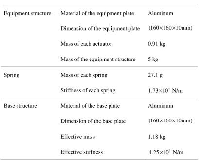
5.1 Physical properties and geometrical data of the four-spring active vibration isolation system.... 145
5.2 Natural frequencies of a free-free-free-free plate, when the length and width of the
plate a=b=0.16 m, the thickness h=0.01 m, Young’s modulus E=69 Gpa, density
3 2700 kg/m
ρ= and Poisson’s ratio ν =0.33. i is the number of half-waves in mode shape along horizontal axis and j is the number of half-waves in mode shape
Nomenclature
Abbreviations
APF Acceleration-Position Feedback AVF Absolute Velocity Feedback IFF Integral Force Feedback IR Internal Resonance LPF Low-Pass Filter
PPF Positive Position Feedback RVF Relative Velocity Feedback SDOF Single-degree-of-freedom
Symbols
A, D Coefficient matrix
A , B , U , V Complex wave amplitude C Capacitor
D Mean diameter of the coil of a helical spring
(
)
D jω Primary disturbance
E, E* Young’s modulus and complex Young’s modulus F Force
(
)
s
F jω Secondary actuator force
G, G* Shear modulus and complex shear modulus
(
)
G jω Plant frequency response function
(
) (
)
G j
ω
H jω
Open-loop frequency response function(
)
'
G jω Plant frequency response function from actuator force to absolute equipment velocity for the stabilized system
lag
G Frequency response function of a lag compensator
lead
Nomenclature
( )
H jω Frequency response function of a feedback controller
(
)
APF
H jω Frequency response function of the APF controller
(
)
IFF
H jω Frequency response function of the IFF controller
(
)
LPF
H jω Frequency response function of a first order low-pass filter
(
)
PPF
H jω Frequency response function of the PPF controller I Second moment of area
J Quadratic performance index
e
J Polar moment of inertia of the equipment
s
J Polar second moment of area of the isolator
B
K Static bending stiffness
b
K , Kb* Stiffness and complex stiffness of the base g
K Gain margin
j
K Modal stiffness of the jth mode
L
K Static longitudinal stiffness
S
K Static shear stiffness
s
K Static stiffness of a helical spring
T
K Static torsional stiffness L Length
L
∆ Deflection of a helical spring j
M Modal mass of the jth mode
N Number of total coils of a helical spring
P Positive-definite real symmetric matrix
a f
P Time averaged power generated by the active control force
Q Positive-definite or positive-semidefinite real symmetric matrix
b
Q Internal force applied to the base from the isolator
e
Q Internal force or moment applied to the equipment from the isolator
1 x
Q , Qx2 Internal force applied to one end of the upper part of the isolator 1
y
Q , Qy2 Internal force applied to one end of the lower part of the isolator 1
Q , Q2 Internal force or moment applied to one end of the isolator
Nomenclature
1
R , R2 Resistor
S Cross-sectional area
b
S Power spectral densities of the base disturbance
e
S Power spectral densities of the equipment response T Transmissibility
a
T Force transmissibility
F
T Torsion moment
1
T Coefficient of a lead compensator
2
T Coefficient of a lag compensator
massless
T Modulus of the transmissibility for the massless isolator max
T Maximum modulus of the transmissibility min
T Minimum modulus of the transmissibility F
U Shear force strain energy
T
U Torsion strain energy
total
U Total strain energy
(
)
W jω Response of the system bb
Y Input mobility of the base when coupled to the rest of the system
eb
Y Transfer mobility from the force on the base to the equipment velocity when the system is coupled
' eb
Y Transfer mobility from the force on the base to the equipment velocity when the stabilized system is coupled
ee
Y Input mobility of the equipment when coupled to the rest of the system '
ee
Y Input mobility of the equipment when coupled to the rest of the stabilized system
er
Y Transfer mobility from the force applied to the point r to the equipment velocity when the system is coupled
rr
Y Point mobility from the force applied to the point r to the velocity at point r when the system is coupled
rb
Nomenclature
ts
Y Mobility from the excitation point s to the response point t in a multi-degree-of freedom system
a
Z Total impedance of the additional SDOF system
B
Z Impedance matrix of a finite sliding-free Euler-Bernoulli beam under lateral vibration
b
Z Impedance of the base
e
Z Impedance of the equipment
I
Z Impedance matrix of a distributed parameter isolator
i
Z Impedance of the massless isolator
ia
Z Impedance of the combined suspension of the additional SDOF system
L
Z Impedance matrix of a finite rod under longitudinal vibration
ma
Z Impedance of the mass in the additional SDOF system
S
Z Impedance matrix of a finite shear beam under lateral vibration
T
Z Impedance matrix of a finite rod under torsional vibration
x
Z Impedance matrix of the upper part of the isolator
y
Z Impedance matrix of the lower part of the isolator
t
Z , Zte, Ztb Total impedance
11, 22
x x
Z Z Point impedance of the upper part of the isolator
12, 21
x x
Z Z Transfer impedance of the upper part of the isolator
11, 22
y y
Z Z Point impedance of the lower part of the isolator
12, 21
y y
Z Z Transfer impedance of the lower part of the isolator
11, 22
Z Z Point impedance of the isolator
12, 21
Z Z Transfer impedance of the isolator
b, d Coefficient vector
c Damping coefficient a
c Damping coefficient of an additional SDOF system
eq
c Equivalent damping coefficient
i
c Complex wave speed in the distributed parameter isolator
l
Nomenclature
s
c Complex wave speed for the finite rod undergoing torsional vibration and the shear beam undergoing lateral vibration
d Wire diameter of the coil of a helical spring
i
e Input of an electrical circuit for a lead compensator
o
e Output of an electrical circuit for a lead compensator f Primary force applied to the base
a
f , fa1, fa2 Active control force '
a
f Force transmitted to the base through the additional SDOF system
B
f , fB1, fB2 Blocked force b
f External force applied to the base
e
f External force applied to the equipment
T
f Transmitted force
1
f Corner frequency of the frequency response function 1+ jωλ in Hz 2
f Corner frequency of a first order low-pass filter in Hz h, h1, h2, g Constant gain
max
h Maximum control gain *
k Complex wavenumber
a
k Stiffness of an additional SDOF system
b
k , kb* Bending wavenumber and complex bending wavenumber l
k , kl* Longitudinal wavenumber and complex longitudinal wavenumber s
k , ks* Shear wavenumber and complex shear wavenumber
m Mass a
m Mass of an additional SDOF system
b
m Mass of the base
e
m Mass of the equipment
i
m Mass of the isolator
s
m Mass of a helical spring
n Number of active coils of a helical spring
Nomenclature
( )
u L Displacement or angle at one end of the isolator ( )
u L& Velocity or angular velocity at one end of the isolator ( , )
u x t Displacement or angle of an element along the isolator (0)
u Displacement or angle at one end of the isolator (0)
u& Velocity or angular velocity at one end of the isolator
b
u Displacement of the base
b
u& Velocity of the base
e
u Displacement of the equipment
e st
u δ Amplitude ratio
(
ueδ
st)
massless Modulus of the amplitude ratio for the massless isolator maxe st
u
δ
Maximum modulus of the amplitude ratio mine st
u
δ
Minimum modulus of the amplitude ratio eu& Velocity of the equipment 2
e
u& Mean square velocity of the equipment
e
u&& Acceleration of the equipment
l
u Displacement of the middle mass of the mass-spring-mass-spring- mass system
l
u&& Acceleration of the middle mass of the mass-spring-mass-spring- mass system
r
u& Velocity of the point r along the isolator where the active force applied
x, x& State vector
x Length of the upper part of the isolator
y Disturbance vector
y Length of the lower part of the isolator
Ω, Ωa, Ωj Frequency ratio b
Γ Ratio of the base resonance frequency to the equipment resonance frequency
f
Γ Ratio of the corner frequency of the low-pass filter to the system fundamental resonance frequency