NOVEL HARMONIC ELIMINATION TECHNIQUE FOR
CASCADED H-BRIDGE INVERTER USING SAMPLED
REFERENCE FRAME
1VEERAKUMAR,2NIRMAL KUMAR, 3SATHISHKUMAR, 4RAJESH
1Department of Electrical and Electronics Engineering, Bannari Amman Institute Of Technology,
Anna University, Tamil Nadu-India
2Principal, Karpagam College of Engineering
Anna University, Tamil Nadu-India
3Department of Electrical and Electronics Engineering,Suriya Engineering College
Anna University, Tamil Nadu-INDIA
4
Department of Electrical and Electronics Engineering,Info College of Engineering Anna University, Tamil Nadu-INDIA
Email:1[email protected]
,
2[email protected],
3[email protected] 4[email protected]ABSTRACT
This paper proposes SWARM Intelligence based algorithm for selective harmonic elimination using SSVPWM in modified H-bridge multilevel inverter. This algorithm uses sampled reference frame to generate reference sine signal. The computation time is less as compared to that of sector identification algorithms. Also, SWARM intelligence based algorithm doesn’t require any look-up table potentiometer connected to ADC channel of this dsPIC which decides the V/F ratio and the keypad connected to PORT C which decides the harmonic order that has to be eliminated. The hardware setup for the proposed method for 5-level inverter has been developed successfully for 2.2Kw Induction motor. The experimental result shows that this method can effectively reduce the selective harmonic in modified cascaded H-Bridge Multilevel inverter.
Keywords: Swarm Space Vector Pulse Width Modulation (SSVPWM), Artificial Neuro Fuzzy Inference System (ANFIS), Selective Harmonic Mitigation Pulse Width Modulation (SMHPWM), Selective Harmonic Pulse Width Modulation (SHPWM), Total Harmonic Distortion (THD), Fast Fourier Transform (FFT),Interrupt Service Subroutine (ISR).
1. INTRODUCTION
Artificial intelligence has become an optimization tool for solving problems having no known solution[1].This algorithm is used for eliminating harmonics in multilevel inverter [2, 3, 4]. This inverter uses single battery source [5, 6] to obtain n-level output to drive the electric vehicle. Selective harmonic elimination is preferred to eliminate the lower order harmonics in high power drives with low cost DSP based SVPWM generation for H-bridge inverter using sampled frame [7,8]. Many genetic algorithms are proposed to solve the complex problems with unknown result [9, 10, 11] and it also increases computation time to solve more iteration even high end DSP controller [12] requires more time to solve.
The proposed sampled reference frame algorithm will reduce the computation time of the processor considerably. A SVPWM scheme based on the above principle has been used where the switching time for the inverter legs is directly determined by sampled voltages. The harmonic waveform notch insertion is determined by Fourier series expansion. The sampled voltage is obtained by maximum and minimum values of phase voltage [13].
ISSN: 1992-8645 www.jatit.org E-ISSN: 1817-3195
selecting optimum firing angle. Also this system operates at very high frequency, so side band frequencies are shifted to higher band.
In this paper the above related issues were addressed using dsPIC platform running at 20MHz. The whole program is driven by ISR. The motor control PWM module in the dsPIC is used to generate SVPWM for the proposed 5-Level inverter for the 2.2KW Induction motorand has been tested successfully.
2. PROPOSED SYSTEM
[image:2.612.334.520.183.322.2]H-bridge inverter using single source H-Bridge Multilevel inverter is shown in Figure 1 with the single DC source is proposed to test this algorithm.
Figure 1: Circuit Diagram Of Proposed System
[image:2.612.115.286.285.438.2]The overall block diagram of the proposed system is shown in Figure 2.
Figure 2: Block diagram of proposed system
The proposed algorithm uses only sampled amplitude of the reference phase voltages to produce reference sine signal. On the other hand the conventional algorithm requires sector identification and trigonometric functions which
require more machine cycle for computation. To improve the performance and reduce the machine cycle the purpose algorithm has been introduced. The generated third harmonic sine wave then add to carrier wave with different offset as shown in Figure 3 which decides the harmonic order to be eliminated.
Figure 3: Offset Has Added To Triangle Carrier With Modified Sine Wave
3. GENERATING REFERENCE SIGNAL
FOR SVPWM USING SAMPLED PHASE VOLTAGE
[image:2.612.335.504.463.591.2]The sampled frame algorithm requires only amplitude of phase voltages. By calculating maximum, minimum and middle vales from phase voltages the effective time period is calculated illustrated in Figure 4.
Figure 4: Effective time calculation for given sampling time
This does not require any sector information or sector time calculation.
S S S
a b c
dc dc dc
T
T
T
V
V
V
V
V
V
(1)
Where Va, and are the phase voltages,
[image:2.612.85.279.513.657.2]By the above expression find out and
(
)
max max as, bs, cs
T = T T T (2)
(
)
min
min
as,
bs,
csT
=
T T T
(3), Maximum and minimum amplitude of phase voltage for the sample time of
max min
eff
T
=
T
−
T
(4)eff
T Effective time
0 S eff
T
= −
T
T
(5)0
T
zero vector component for the samples time ofS
T
Offset is required to shiftT
0 to positive0 S eff min
T
= −
T
T
−
T
(6)
0 min
2
offT
T
=
−
T
(7)Gating pulse for phases a, b and c is
(8)
(9)
(10)
Decides the carrier offset voltage amplitude,
[image:3.612.98.526.49.723.2]the effective pacing of is done by SWARM intelligence algorithm has depicted in Figure 5.
Figure 5: Firing Angle Of Notches Introduced In Quarter Wave
Placing of optimum firing angle is done by solving and Fourier series expression:
(
1 2 3)
2
2 cos
cos
cos
...
1
2
dc nV
V
n
n
n
n
π
α
α
α
=
−
+
− −
(11)The above equation (9) can be solved and can be rewritten as
( )
( )
( )
( )
( )
α1 α2
0 α1 α3 π/2
α2 αp
sin nθd sin nθdθ 1 4 Vdc
Vn rms
π 2 2
sin nθdθ .. sin nθdθ
− + = −
∫
∫
∫
∫
(12)The generalized expression for selective harmonic equation can be modified for the required notches i.e. α1, α2, α3 and α4. From 0 to α1 the notch lies in
positive side from α1 to α2 the notch lies in
negative side.
Fromα2 to α3 the notch lies in positive
side. This extends up-to Quarter wave symmetry.
From π
2 to
π
the notches will be symmetrical.Finally equation (10) can be written as
( )
( )
( )
( )
( )
α1 α2
0 α1
α3 α4
α2 α3
sin n
θ
d
θ
sin n
θ
d
θ
1 4Vdc
Vn rms
π
2
2
sin n
θ
d
θ
sin n
θ
d
θ
−
=
+
+
∫
∫
∫
∫
(13) Above equation is for only half wave symmetry
that is from 0 to π
2 . By writing equation 11 two
times full wave symmetry 0 to π can be obtained.
In this proposed work harmonic amplitude of 5th order, 7th order, 11th order and 13th order have been eliminated. To find the optimum firing angle for α1, α2, α3 and α4 equation 11 is further
reduced. Amplitude of the fundamental voltage in rms:
1 2
3 4
cosn
cosn
Vrms 0.45 Vdc 2
1
cosn
cosn
∝ −
∝
=
−
+
∝ −
∝
(14)To reduce 5th, 7th, 11th and 13th order harmonics the above equation can be written as:
1 2
th
3 4
cos5
cosn5
5 orderamplitude 0
0.5
cosn5 cosn5
∝ −
→ =
−
+
−
(15)1 2
th
3 4
cos7
cos7
7 orderamplitude 0
0.5
cos7
cos7
∝ −
∝
→
−
+
∝ −
∝
(16)1 2
th
3 4
cos11
cos11
11 orderamplitude 0
0.5
cos11
cos11
∝ −
∝
→
−
+
∝ −
∝
(17)ga as off
gb bs off
gc cs off
T
T
T
T
T
T
T
T
T
=
+
=
+
ISSN: 1992-8645 www.jatit.org E-ISSN: 1817-3195
1 2
th
3 4
cos13
cos13
13 orderamplitude 0
0.5
cos13
cos13
∝ −
∝
→
−
+
∝ −
∝
(18)4. SWARM OPTIMIZATION ALGORITHM
Many algorithms have been proposed to solve the above equations to reduce the harmonics to standard grid code which is tabulated in Table 1. The proposed SWARM optimization algorithm has been proposed to solve the equation along with the sampled reference frame SVPWM.This facilitates the reduction of harmonics within the grid code. Finally there are five equations and four unknowns. By solving the equation α1, α2, α3 and α4 will be
obtained. This is done by SWARM optimization which involves three steps.
4.1 Knowledge Base Generation 4.2 SWARM Training
4.3 Fine Tuning
4.1 KNOWLEDGE BASE GENERATION
The switching angles are maintained at
0 1 2 3 4. . . 1
2 n
π θ < θ < θ < θ < θ θ − < ,
upto Quarter wave
4.2 SWARM Training
The system consists of an adaptive network and ANFIS that aid in the elimination of harmonics that are generated by the electric vehicle and hybrid electric vehicle. The neural network to be utilized for the system is in Figure. 6 ANFIS consists of five fuzzy layers namely product layer, normalized layer, defuzzy layer, and total output layer. The dataset will be needed to train the network. This can be made capable by taking Ra as the reference
dataset and extracting the patterns from R. The R
dataset K class satisfies the th Ra dataset in same
class. This form is one of the training elements in
training dataset
R
train.In the same way, this process is performed for all the patterns present in R and therefore the total training dataset is formed and shown in Table 2.4.3 Fine Tuning
Generally the ANFIS output is not accurate i.e., the switching angle generation and the corresponding voltage and THD are not equal. So it is required to increase the performance and
accuracy of the system by using tuning process. In this tuning process the constant elements like
T
THD and they VT are taken into account. The
tuning process is described below.
Step 1 : Finding the Error harmonic (
E
1)2
1
0.5(
)
T
E
=
THD
−
THD
Where,
THD
Tis feedback Distortion value, THD is reference Distortion value.Step 2 : Finding the error voltage
E
22 2 0.5( )
T ph
E = V −V Where,
V
T is target voltage,V
phis phase voltage.Step 3: Calculate the average error voltage
E
avg1 2 0.5( )
avg
E = E +E
Step 4: Determine the new switching angle from the error voltage
E
avg[ * * * ]
new old old
avg
E r
θ = γ θ +θ
new
θ
is new switching angle, the tuning constant(
γ
=
0.2)
, r is random numbers selected within the rangeold
θ
is the value of switching angle calculated.Step 5: Check the firing angle that lies within the limit
1 2
...
i i i i n
θ θ
<
+<
θ
+<
<
θ
+ ;i
>
0
If not within the limit do the following,
1
new new
i i
θ
>
θ
+ is the error value,i
>
0
Recover the firing angle
θ
i+1newwith followingrelation,
If
θ
inew<
θ
i+1oldtrueθ
i+1old process to next steps.If false,
θ
i+1new=
θ
inew+
r
, Where,r
=
0,1
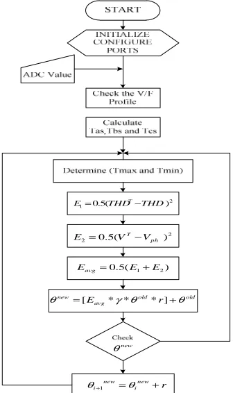
(Random numbers).5. CONTROL ALGORITHM
The control flowchart of the proposed algorithm is shown in Figure 7. This algorithm involves only normal arithmetic operation. Because of this, the execution time of the proposed method is very less. This proposed system has been tested in MATLAB environment and the optimization is applied by training and generating through trained fuzzy set for 3rd and 5th order harmonic.
The simulation results depicted in figure 8 shows the 3rd order harmonics waveform injection which has 100% THD and the 3rd and 5th order harmonic waveform superimposed in the fundamental waveform.
Figure 6: The Structure Of Proposed SWARM Algorithm Technique
2 1 0.5(THD THD)
E= T−
2
2 0.5( ph )
T V V
E = − 2
2 0.5( ph )
T V V
E = −
) ( 5 . 0 E1 E2
Eavg= +
old old
avg
new E γ θ r θ θ =[ * * * ]+
new θ
r new i new i+ =θ +
[image:5.612.318.516.79.200.2]θ 1
Figure 7: Block Diagram Of SWARM Algorithm Flow Chart
Figure 8: FFT Window Of Third Order Harmonic Injection Waveform In MATLAB
[image:5.612.319.497.265.370.2]Figure 9 illustrates 48% and 5th order has 100% THD.
Figure 9: FFT Window Of Fifth Order Harmonic Injection Waveform In MATLAB
Figure 10 shows switching angle obtained from MATLAB for given four notches.
Figure 10: Comparison Of Optimum Switching Angle And Modulation Index
6. EXPERIMENTAL RESULT
Table 3 shows the experimental parameters. The hardware for 5-level MOSFET H bridge cascaded multilevel inverter topology is shown in Figure.11 with dsPIC working environment has been developed.
A1
A2
B1
B2
?
?
N
N
?
X Y
X Y
x
y
? 1
? 2 ? 1'
? 2'
F ?
1 'F1
?2 ' F2
[image:5.612.109.299.271.369.2] [image:5.612.112.280.415.698.2] [image:5.612.311.523.443.564.2]ISSN: 1992-8645 www.jatit.org E-ISSN: 1817-3195
Table3: Experimental Parameters
Figure 11: Laboratory Model Of Proposed Hardware
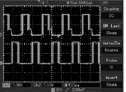
[image:6.612.90.291.544.698.2]The output waveforms depicted in Figure 12 and 13 show the notches that are introduced in switching pulses.
Figure 12: Gating Pulse Of R Phase Positive And Negative Half Cycle
Figure13: Gating Pulse Of Y Phase Positive And Negative Half Cycle
Figure 14 shows the switching selection logic which desirers the conduction time period of MOSFET of VSI and H bridge inverter. Figure 15 shows the booster driver IR2110.
The proposed inverter operates at the switching frequency of 20 kHz.
[image:6.612.318.522.551.700.2]Figure14: Output Of Switching State Selective Logic
Figure 15: Outputs From Booster Strip
HARDWARE SPECIFICATIONS
Motor Rating 2.2 Kw
Current 5 A
Voltage 415 V
Speed 1500 Rpm
Controller dsPIC30F4011
MOSFET IRF548N
Switching Frequency 20KHz
Inverter Topology Cascaded H-Bridge
Comparison graph illustrated in Figure 15 shows the distortion factor and harmonics order for the proposed algorithm with standard grid code.
[image:7.612.314.519.121.253.2]The graphical data displays the distortion factor. The THD value of SSPWM value is small as compared to SMHPWM and SHPWM algorithm. The simulation is carried for 3rd, 5th, 7th and 11th harmonic order and hardware is tested in 3 phase 3.3Kw induction motor. The Table 4 depicted the comparison of hardware and simulation results.
[image:7.612.91.300.219.366.2]Figure 16: Comparisons Of Different Switching Schemes
Table 4: Comparisons of simulation and hardware.
However, there are some deviations due to unstable simulation results caused by untrained dataset. A negative notch introduced in PWM signal for the elimination of 3rd order harmonics
is illustrated in Figure 12 and 13. These PWM signal is boosted using IR2110, MOSFET driver. The output of the proposed five level inverter topology without harmonic elimination is illustrated on Figure 16, with distorted load current waveform. The FFT window is depicted in Figure 15. The load current waveforms are shown in Figure 17 and the five level voltage load voltage waveform after
implementing the proposed SWARM algorithm is depicted in Figure 18.
[image:7.612.314.518.283.398.2]Figure 17: Current Waveform Without Mitigation Technique
[image:7.612.84.283.421.577.2]Figure 18: FFT Window Without Harmonic Mitigation
[image:7.612.317.518.424.546.2]Figure 19: Current Waveform With Mitigation Technique
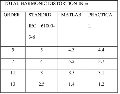
Figure 20: Load Voltage Waveform TOTAL HARMONIC DISTORTION IN %
ORDER STANDRD
IEC
61000-3-6
MATLAB PRACTICA
L
5 5 4.3 4.4
7 4 5.2 3.7
11 3 3.5 3.1
[image:7.612.315.517.574.703.2]ISSN: 1992-8645 www.jatit.org E-ISSN: 1817-3195
Figure 21: FFT Window of proposed system
Figure 19 illustrates the FFT window with fundamental frequency with 100% of its amplitude. The low order harmonics of 3rd, 5th, 7th and 9th order are totally eliminated.
7. CONCLUSION
In this paper selective harmonic elimination has been achieved using values of sampled phase voltages in dsPIC30F4011 environment for the cascade H bridge multilevel inverter for harmonic order of 3, 5, 7 and 11 and the final THD value is only 1.2% which is very less compared to SMHPWM.
This proposed method uses user selectable harmonic elimination option. Also the switching frequency of inverter is about 20 kHz which results in less EMI and THD within the range of harmonic standards EN 50160, CIGREJWGC4.07 and IEC 61000-3-6 from both individual harmonics and THD point of view. The closed loop system increase dynamic response by employing inner current limit and outer speed limit control. This method does not have any restrictions for higher levels and topologies. The proposed system can be used or distributed electrical system such as electric tractions, solar inverter and wind energy generation system.
REFERENCES:
[1] Ahamad M. Ibrahim. Fuzzy logics for Embedded Systems Applications.3rd ed. USA: ELSIVER Science; 2003.
[2] Mahmoud Gaballah, Mohammed El-Bardini. “Low cost digital signal generation for driving space vector PWM inverter”, Ain Shams
Engineering Journal,Vol.4, No.7, 2013, pp.
1-12.
[3] Ayong Hiendro, “Multiple Switching Patterns for SHEPWM Inverters Using Differential Evolution Algorithms”, International Journal
of Power Electronics & Drive System, Vol.1
No. 6, 2011, pp. 94-104.
[4] Ray Rup Narayan, Chatterjee Debashis, Goswami Swapan Kumar. “An application of PSO technique for harmonic elimination in a PWM inverter”, Application Soft Comptuting,Vol 4, No. 5, 2009,pp. 1315–1320.
[5] Zhong Du, Burak Ozpineci, Leon M. Tolbert, John N. Chiasson. “DC–AC Cascaded H-Bridge Multilevel Boost Inverter with No Inductors for Electric/Hybrid Electric Vehicle Applications”, IEEE Transaction Industrial
Electronics, Vol.7, No.45,2009,pp.963–970.
[6] Zhong Du, Leon M. Tolbert,John N. Chiasson. “A Cascade Multilevel Inverter Using a Single DC Source”, IEEE Proceedings on Industrial
Application, Vol.4, No.32,2006,pp. 963–970.
[7] K. Sivakumar, Anandarup Das, Rijil Ramchand, Chintan Patel, K. Gopakumar, “A Hybrid Multilevel Inverter Topology for an Open-End Winding Induction-Motor Drive Using Two-Level Inverters in Series With a Capacitor-Fed H-Bridge Cell”, IEEE Transaction Industrial Electronics, Vol.10,
Vol. 57,2010,pp. 87-95.
[8] R.S. Kanchan, M.R. Baiju, K.K. Mohapatra, P.P. Ouseph and K. Gopakumar,”Space vector PWM signal generation for multilevel inverters using only the sampled amplitudes of reference phase voltage”s, IEEE Transaction Electrical
Power Applications, Vol.5, No. 152,2005,pp.
297-309.
[9] F. Valdez, P. Melin, O. Castillo, “An improved evolutionary method with fuzzy logic for combining Particle Swarm optimization and Genetic Algorithms”.
Applied Soft Computing,
Vol,11,No.11,2011,pp.2625-2632.
[10] CristianMusardo, Giorgio Rizzoni, Fellow,and Benedetto Staccia, A-ECMS: An Adaptive Algorithm for Hybrid Electric Vehicle Energy Management,. European Journal of Control, Vol,11 (Issue 11): 509-524, January 2005. [11] Parekh Rakesh, “V/F control of 3-phase
induction motor using space vector modulation”, Microchip Technology Inc ,2005. [12] J. Sun, S. Beineke, and H. Grotstollen, “DSP-based real-time harmonic elimination of PWM inverters”, Power Electronics Specialists Conferences; Vol.5, No. 12,1994,pp- 679-685.
[13] Marzoughi A, Imaneini H, “An optimal selective harmonic mitigation for cascaded H-bridge converters”, Environmental and Electrical Engineering Conferences; Vol.11,
[14] Alinaghi Marzoughi, Hossein Imaneini, “An optimal selective harmonic mitigation technique for high power converters”,
International Journal of Electrical Power & Energy Systems Vol. 1, No. 49,2013,pp. 34–39.
[15] F. Swift and A. Kamberis, “A new Walsh domain technique of harmonic elimination and voltage control in pulse width modulated inverters”, IEEE Transaction Power Electronics, Vol. 7, No. 8,1993,pp. 170-185.
[16] F. Valdez, P. Melin, O. Castillo, “An improved evolutionary method with fuzzy logic for combining Particle Swarm optimization and Genetic Algorithms”.
Applied Soft Computing , Vol. 3, No.