University of Southampton Research Repository
ePrints Soton
Copyright © and Moral Rights for this thesis are retained by the author and/or other copyright owners. A copy can be downloaded for personal non-commercial
research or study, without prior permission or charge. This thesis cannot be
reproduced or quoted extensively from without first obtaining permission in writing from the copyright holder/s. The content must not be changed in any way or sold commercially in any format or medium without the formal permission of the
copyright holders.
When referring to this work, full bibliographic details including the author, title, awarding institution and date of the thesis must be given e.g.
AUTHOR (year of submission) "Full thesis title", University of Southampton, name of the University School or Department, PhD Thesis, pagination
University of Southampton
Power scaling and nonlinear
frequency conversion of
single-frequency lasers based on Nd:YLF
By
Timothy Martin James Kendall
A thesis submitted for the degree of Doctor of Philosophy Faculty of Science
Department of Physics Optoelectronics research Centre
2 Abstract
Faculty of science Department of Physics University of Southampton
Doctor of Philosophy
Powers scaling and nonlinear frequency conversion of single-frequency lasers based on Nd:YLF
By Timothy Martin James Kendall
This thesis presents a strategy for power-scaling diode-end-pumped solid-state lasers based on Nd:YLF operating on the 1.053µm line whilst retaining, efficient, single-frequency, diffraction limited output, the characteristics of low power operation. This strategy reduces the effects of energy transfer up-conversion (ETU), which can decrease the lifetime of the upper lasing level and increase the heat generated per unit volume within the laser rod, increasing the effects of detrimental thermally related problems such as thermal lensing, stress-induced birefringence and stress induced laser rod fracture. Also a passive technique for mode-hopping-suppression is described, allowing the oscillating frequency within the laser cavity to tune over many axial mode spacings before a mode-hop occurs. In order to de-couple the problems of laser resonator power scaling from the maintenance of robust and reliable single-frequency operation, the Nd:YLF laser oscillator output is amplified via Nd:YLF based amplifier stages. A model is presented of the effects of ETU on thermal lensing and small signal gain within the amplifiers along with projected results for further power-scaling prospects.
Using the master oscillator design strategy, in a ring-cavity configuration, we demonstrate 4.5W of single-frequency output (for 20W incident pump power), in a diffraction limited beam (M2<1.1) throughout the entire incident pump range. The passive technique for mode hopping suppression allowed the oscillating frequency to be tuned over 8GHz (~14 axial mode spacings) before mode hopping occurred. The amplifier stages power-scaled the output from the master oscillator to ~20W whilst maintaining diffraction limited beam quality (M2<1.1). In a pulse regime the amplifiers demonstrated a small signal gain of ~2000 giving 1.2kW peak power in a 100ns pulse.
3
Acknowledgements
Before the “big read”, it is quite normal to thank a few people for all their help and support. I on the other hand have to thank a vast amount of people for telling me to “pull my finger out” and “get on with it”.
Not one part of this would have been possible without the help of the Advance Solid-state Sources Group, starting with Paul (the guy pointing in the right direction), Ian (the guy pointing mathematically in the right direction), Pu, Mike, Deyuan (the guys who kept on asking me if it was finished yet) and finally Dr. Andy Clarkson (the guy that never once stopped giving me new angles to look at). Also thanks within the department has to go to Simon, Chris and Tim (the “hands-on” guys) without whose help I would probably be sobbing on the floor of the lab wondering why the “thingy does not fit in the doodaa”. Also thanks to Eve and Heather for helping me sort out all and every type of paper work possible with lots of smiles.
Finally the “non-physics people” (the guys who never ask me how work is going just in case I tell them). First of all, any of the lot I still know and drink with in Ilkley (well done lads, you now have a mention in the British Library), Mum and Dad (the guys without which literally “non of this would have been possible”), Sifu and the rest of the Kung Fu club at Southampton university (the guys that helped me vent some rage – you have know idea how much that helped) and finally Bryony (the only one of the guys on the list that will hit me for calling her a guy and get away with it), without you in my life this thesis would probably be a lot longer – thank-you.
A formal acknowledgment must also go to Dr Ian Musgrave with his help of the mathematics in Chapters 3 and 4. During the course of his work with Nd:YVO4 our
4
Contents
ABSTRACT
... 2
ACKNOWLEDGEMENTS... 3
CHAPTER 1:
INTRODUCTION
... 9
1.1 General Introduction ... 9
1.2 Background ... 10
1.2.1 Low power diode end-pumped solid state lasers ... 11
1.2.2 Optical parametric oscillators ... 14
1.2.3 Quasi phase-matching... 16
1.2 Thesis overview ... 17
1.3 References... 20
... 23
CHAPTER 2:
DIODE-END-PUMPED SOLID-STATE LASERS
... 23
2.1 Introduction... 23
2.2 Design criteria for the efficient operation of diode-end-pumped four-level solid-state lasers in the low-power regime... 24
2.2.1 Threshold and slope efficiency... 24
2.2.2 Single-frequency operation ... 26
2.2.3 Techniques for single-frequency operation ... 28
2.2.4 Diode pump sources... 33
2.2.5 Diode beam delivery schemes for high-power diode pump
sources... 35
2.3 Thermal effects... 37
2.3.1 Heat Generation... 37
2.3.2 Thermal Lensing... 40
2.3.3 Thermally Induced Birefringence ... 46
5
2.3.5 Power-scaling limitations ... 49
2.4 Summary ... 51
2.5 References... 53
... 56
CHAPTER 3:
SINGLE-FREQUENCY ND:YLF MASTER
OSCILLATOR
... 56
3.1 Introduction... 56
3.1.1 Nd:YLF ... 58
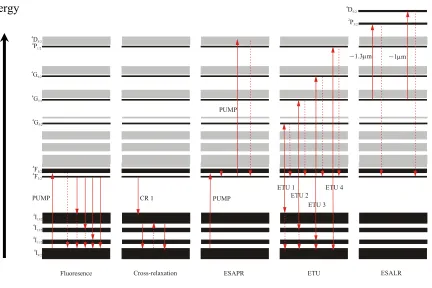
3.1.2 Energy transfer up-conversion in Nd:YLF ... 62
3.1.3 The effect of ETU on Nd:YLF fluorescence lifetime ... 63
3.1.4 The effect of ETU on Nd:YLF laser threshold ... 65
3.2 Single-frequency selection, Mode Hopping and Mode Hop Suppression ... 70
3.2.1 Introduction... 70
3.2.2 Passive Technique for Mode Hop Suppression ... 71
3.3 Pump source design and performance... 74
3.4 Nd: YLF bow-tie ring cavity... 75
3.4.1 Cavity Design ... 75
3.4.2 Master Oscillator Cavity Loss-Difference ... 78
3.4.3 The Effects of Up-conversion on the Master Oscillator ... 83
3.4.4 Summary... 84
3.5 Experimental Results ... 85
3.6 Summary ... 89
3.7 References... 89
... 92
CHAPTER 4:
HIGH-POWER SINGLE-FREQUENCY
MASTER-OSCILLATOR-POWER-AMPLIFIER
... 92
4.1 Introduction... 92
4.2 Amplifier theory... 93
6
4.2.2 Saturated gain operation... 98
4.2.3 Amplified spontaneous emission ... 100
4.2.4 Parasitic oscillations... 101
4.3 Energy transfer up-conversion and small signal gain ... 103
4.3.1Impact of ETU on small signal gain ... 103
4.4 Thermal lensing in amplifier... 106
4.4.1 Reducing thermal loading in the amplifier ... 106
4.4.2 Thermal lensing on the 1053nm line in an Nd:YLF amplifier
... 106
4.4.3 Degradation in signal beam quality... 111
4.4.4 Minimum pump beam spot size ... 114
4.3.5 Amplifier double rod geometry ... 115
4.3.5 Qcw Operation master oscillator configuration... 122
4.5 Experimental results... 124
4.6 Discussion ... 137
4.7 Summary ... 140
4.8 References... 141
... 143
CHAPTER 5:
SINGLY RESONANT CW OPTICAL PARAMETRIC
OSCILLATORS
... 143
5.1 Introduction... 143
5.1.1 Optical parametric oscillators ... 143
5.1.2 Phase matching ... 146
5.1.3 Quasi phase matching ... 149
5.1.4 Singly resonant oscillators (SROs) ... 154
5.2 CW SRO threshold, slope efficiency and operation ... 156
5.2.1 CW SRO threshold ... 156
5.2.2 CW SRO slope efficiency... 160
7
5.3.1 Mechanical vibration and pressure fluctuations ... 162
5.3.2 Pump stability... 164
5.3.3 Thermal expansion of PPLN ... 165
5.3.4 The temperature dependence of the parametric gain lineshape
... 166
5.4 CW SRO mode hopping suppression... 171
5.4.1 The theory of mode hop suppression within an SRO ... 171
5.4.2 The implications of mode hopping suppression with an SRO
... 175
5.5 CW SRO alignment technique and application ... 177
5.5.1 Confocal SRO cavity ... 177
5.5.2 Four mirror linear SRO cavity... 179
5.5.3 Four-mirror ring SRO cavity ... 180
5.6 Discussion and conclusions ... 183
5.8 References... 185
CHAPTER 6:
CW
MODE-HOP-FREE
SROPOS
... 188
6.1 INTRODUCTION
... 188
6.2 FOUR-MIRROR CW OPO CAVITY
... 189
6.2.1 Four-mirror cw OPO without mode-hopping suppression... 189
6.2.2 Four mirror cw OPO with mode-hopping suppression ... 193
6.3 SIX-MIRROR CW OPO CAVITY
... 198
6.4 DISCUSSION AND CONCLUSION
... 204
6.5 REFERENCES
... 206
CHAPTER 7:
CONCLUSIONS AND FUTURE WORK
... 207
7.1 Introduction and thesis summary ... 207
7.2 Nd:YLF master oscillator... 209
7.3 Nd:YLF master oscillator power amplifier ... 210
8 7.5 Summary ... 214
APPENDICESAPPENDIX 1
PUBLICATIONS AND SUBMITTED
PAPERS
... 215
APPENDIX 1
PUBLICATIONS AND SUBMITTED PAPERS
... 216
APPENDIX 2
EFFECT OF ENERGY TRANSFER UPCONVERSION
9
Chapter 1:
Introduction
1.1 General Introduction
Lasers appear everyday within our lives now, whether we are shopping for food or clothes, visiting the dentist or doctor or even simply listening to music, lasers can be involved in some way or another. Scaling the output powers from solid-state lasers to satisfy the needs of ever-demanding applications continues to be a very important area of research within the lasers and optics community. For many of these applications the requirements for high output power is also accompanied by the need for high efficiency and good (preferably TEM00) beam quality. These operating
10 (SROPO) pumped by a solid-state laser source. The design of such a source and its implementation is complicated not only for the need for high-power and diffraction-limited beam quality from the solid-state source, but also because of the need for robust, mode-hop-free, single-frequency operation, which is very difficult to achieve at high pump powers. A further complication is mode-hopping in the SROPO caused by mechanical vibration and temperature fluctuations, which can be a very serious problem.
The research project described in this thesis had two main goals: (1) To investigate an approach for power-scaling of single-frequency operation in the 1µm wavelength regime using a novel master-oscillator-power-amplifier architecture based on Nd:YLF and employing a passive technique for suppressing mode-hopping in the master oscillator. (2) To demonstrate efficient cw SROPO’s based on periodically-poled lithium niobate (PPLN), pumped by the Nd:YLF MOPA, and to investigate the application of the same passive technique for suppressing mode-hopping to a cw SROPO with the goal of achieving reliable single-frequency operation and mode-hop-free wavelength tuning.
The remainder of this opening chapter will briefly review the historical background relevant to the project and explain in more detail the motivation for the work. Finally this chapter will conclude with a short overview of the thesis contents.
1.2 Background
The need for high-power single-frequency solid-state lasers has increased dramatically over the last decade. Emerging fields of gravitational wave-detection, LIDAR, spectroscopy and others [1-7] require low noise coherent narrow linewidth sources with high output power, excellent beam quality, high efficiency and a range of operating wavelengths.
11 led to numerous demonstrations of lasers with high efficiency and reliability, as well as good frequency stability, which far exceed the capabilities of typical flash lamp pumped laser geometries albeit with lower output power. Due to the broadband output spectrum emitted by a flash lamp pump source, and the narrower width of the absorption lines in most solid-state laser materials, a large fraction of pump light is not absorbed with the result that the overall efficiencies tend to be rather low. The situation in lamp-pumped systems is further escalated by light being absorbed in high lying energy levels within the laser material, which then decay non-radiatively to the emitting level with the result that the heat loading is rather high requiring large and expensive cooling systems, hence reducing simplicity and compactness of design. A typical lifetime of a flash lamp device is currently around 500-1000 hours whereas a diode device has a lifetime of ~5000-20000 hours [8].
1.2.1 Low power diode end-pumped solid state lasers
Since 1962 when the first diode-lasers were developed [9-11], the recent surge in interest in the use of diode lasers to pump solid-state lasers has lead to the development of numerous devices both research based and commercial that have demonstrated diffraction limited beam qualities, highly efficient outputs and single-frequency operation. The first mention of the use of semi-conductor technology to pump a solid state laser, to our knowledge was by Newman et al [12], who found that radiation near 880nm from the recombination of GaAs diodes, essentially what we know today as an LED (light emitting diode), could excite fluorescence near 1.06µm in Nd:CaWO4. Since then the development and understanding of such devices has
12 As laser sources themselves, diode lasers have a number of disadvantages compared to solid-state lasers. Firstly, their short energy storage lifetimes limits the scope for producing high pulse energies by Q-switching and catastrophic facet damage limits the maximum achievable output power from a single-mode diode device (to <1W). In order to increase the output power of diode lasers it is necessary to construct a linear array of low power devices, with the result that the beam quality is degraded in the array direction. The typical dimensions of a single-mode diode emitter are ~1µm × ~5µm. A multistripe device will have dimensions of ~1µm × ~200µm, which is ~50 times (M2 ~50) diffraction limited in the array direction. Many applications require high brightness beams. The brightness B is defined by the following equation [15]:
2 2 2
x y
P B
M M
λ =
Where P is the power, λ is the wavelength and Mx/y2 are the beam quality factors (M2 is the factor by which the far-field Gaussian beam divergence angle for a given beam waist diameter is multiplied to give the actual far-field divergence, and as such it is entirely equivalent to the number of times diffraction limited quantity [16]), in orthogonal planes x and y respectively. One of the major attractions of diode-pumped solid-state lasers therefore, is that they can allow the poor beam quality diode-laser output to be converted into diffraction limited output, hence increasing the brightness.
Further increases in diode output power are typically achieved by making longer arrays (known as diode-bars) and two dimensional stacked arrays (known as diode-stacks). The latter can produce cw output powers of several kW.
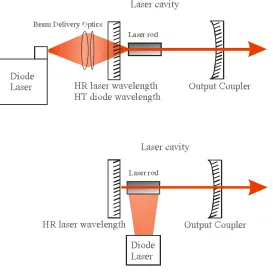
13 favoured for high-power operation. End-pumping generally requires a more complicated arrangement of optics to focus the pump beam to a small beam size and so that it propagates collinearly with, and overlaps with the laser mode. This generally allows much lower thresholds and higher slope efficiencies to be achieved at low pump powers. However, due to high pump deposition density, and high thermal loading density, thermal effects become a serious problem at high pump powers. For this reason, scaling end-pumped lasers to high power levels is quite challenging. Nevertheless, with careful selection of gain material and laser design, and with effective thermal management, end-pumping can be a very attractive and flexible route to high output power as will be shown in this thesis.
Figure 1.1 Diagram displaying two beam delivery schemes – end-pumping (above) and diode-side-pumping (below).
~910nm-14 980nm. These diodes can be matched carefully in terms of choice of pump source, to material in question, for their appropriate absorption bands, and we also have the flexibility to fine tune diode devices by adjusting their temperature and by so doing, optimising pump light absorption. Diode pump light beam delivery, for low power applications (typically <1W) requires very little in terms of heat dissipation and regulation, and is normally implemented by conventional optics, however more sophisticated techniques for high power applications, where thermal effects can have catastrophically degrading effects, will be discussed later in the thesis.
The laser cavity is designed so that the laser mode matches the pump beam size allowing for efficient power extraction, and TEM00 operation. Furthermore,
unidirectional operation can eliminate spatial-hole-burning, therefore, in conjunction with a homogeneously broadened laser material, single-frequency operation can be achieved [17].
Besides, what is generally considered to be the most common laser material dopant, Nd3+, which lases at ~1µm, there are several other known rare-earth ions, each of which have been used as part of diode-pumped solid-state lasers to produce various useful output wavelengths, e.g. Ho3+ at 2.1µm, Tm3+ at 2.0µm and Er3+ at 2.8µm, also, by achieving higher population inversion densities by end-pumping Nd3+,
operation of the lower gain transitions have been achieved at 946nm and 1.3µm [18-24].
1.2.2 Optical parametric oscillators
15 travels with the same velocity as the freely propagating electromagnetic wave, cumulative growth will result. The two incident waves are termed pump and signal, having the frequency νp and νs, and the resulting third wave is termed as the idler
with frequency νi. Under proper conditions, the idler wave can mix with the pump
beam to produce a travelling polarisation wave at the signal frequency, phased such that the growth of the signal wave results. The process continues with the signal and the idler waves both growing and the pump wave decaying as a function of distance within the crystal.
Since this first work, huge amounts of research into OPOs has been carried out with the aim of increasing efficiency and wavelength tuneability primarily, in order to provide a more practical alternative to dye based lasers for fields such as spectroscopy. Since early research in the field, a steady stream of new nonlinear crystals have been developed for use in OPOs. Significantly, in 1984 Donaldson and Tang developed an OPO based on crystalline urea, which when pumped using a UV laser produced a visible output. This was superseded by Fan et al [26]in 1988 who demonstrated an OPO based on β-barium borate (BBO) as the non-linear crystal with the attraction of improved resistance to damage compared to urea. The discovery of BBO and then later LiB3O5 (LBO) by Chen et al in 1989 formed the
catalyst for several commercial pulsed OPO systems.
One critical design parameter in OPO research is the pump power required to reach threshold, which depends on the OPO design, cavity loss, nonlinear crystal and pump beam size. Although diode-pumped solid-state lasers seem ideal candidates for pumping such devices, for singly-resonant oscillators (SROPOs) the threshold pump power is rather high generally requiring high peak power pump sources (either mode-locked or Q-switched). A seemingly simple solution to this problem was to make the OPO resonant at both the signal and idler wavelengths. Such devices are referred to as doubly resonant oscillators (DROs). However, DRO cavities can be difficult to align and are over-constrained by their requirement to satisfy energy conservation, phase-matching and resonance of both oscillating fields leading to instabilities in the output as sub-nanometre changes in cavity length or MHz changes in the pump frequency cause mode hops in the signal and idler fields.
16 demands on the pump laser, particularly if cw oscillation is required. For ~1µm wavelength pumped SROPOs utilising birefringently phase-matched crystals, threshold pump powers typically exceed multiple watts.
1.2.3 Quasi phase-matching
The advent of new designs of nonlinear crystals such as periodically-poled lithium niobate [27] which allow high nonlinear coefficients to be exploited using quasi-phase matching have helped a great deal. The advantage of this is that any interaction within the transparency range of the material can be non-critically phase-matched at a specific temperature, even for interactions where birefringent phase-matching is not possible.
Also, interacting waves can be chosen so that coupling of fields occur through the largest χ(2) tensor, meaning that the largest available non-linear coefficient can be used, increasing the gain for that interaction and lowering the threshold considerably, thus allowing the user to operate a cw SROPO with a threshold of a few Watts [28-33]. Within an SROPO, the frequency of the resonant wave corresponds with the cavity mode closest to optimum phase-matching. In a true SROPO, the required stability for the cavity length to maintain single mode output is identical to that of a conventional laser:
4
res stab
L λ
∆ ≈ ±
where λres is the wavelength of the resonant wave. The stability requirements of the pump laser are more difficult to calculate since it depends on the phase-matching behaviour, however, assuming that the phase-matching is such that the ratio between the signal and the idler remains constant, for a small change in pump frequency, the stability requirement for the pump laser frequency is:
( ) res
stab
nonres
FSR λ
ν
λ
∆ ≈ ±
17
c FSR
d =
where c is the velocity of light in a vacuum and d is the total round trip distance of the optical cavity. The importance of these equations will be discussed in more detail later in this thesis. It must be noted, however, that in terms of OPO applications that require robust and stable outputs, the importance of SROPO cavity stability (thermal instabilities, pressure changes and mechanical noise with SROPO cavities mean they are very susceptible to mode hopping) and pump laser frequency stability are important in order to achieve single mode operation.
1.2 Thesis overview
18 Chapter 2 reviews the basic theory for the performance of diode-end-pumped solid-state lasers and techniques for selecting single-longitudinal mode operation. The main problems hindering power-scaling of end-pumped lasers associated with the highly asymmetric nature and beam quality of high power diode pump sources and heat generation in the laser medium are considered. Methods for alleviating the effects of heat loading in end-pumped edge-cooled laser rods are discussed including a brief overview of different laser crystals for operating at high powers.
Chapter 3 considers the design strategy for the single-frequency Nd:YLF master-oscillator, commencing with a detailed discussion of the merits and disadvantages of Nd:YLF as a gain material. The effect of energy-transfer-upconversion (ETU) on laser performance is considered and a strategy for minimising its impact is described. The Nd:YLF resonator design, which employed a passive technique for suppressing mode-hopping, is described and the results for performance are compared with theoretical expectations. Finally, issues which would need to be addressed in order to scale the oscillator power further are discussed.
Chapter 4 describes the design strategy for a first and second stage Nd:YLF amplifier beginning with a brief justification for the use of a MOPA approach for power-scaling rather than a single oscillator. The influence of amplifier design on small signal gain and power gain is discussed, and the effect of ETU and heat loading on amplifier performance and output beam quality is considered in detail. The rationale for the use of a dual rod multi-pass amplifier scheme is explained and the results for the performance are compared with theory. Finally, the prospects for further improvement in performance and the upper-limit to brightness scaling are considered.
19 Chapter 6 describes the design and performance of various continuous-wave OPOs based on periodically-poled lithium niobate. The rationale behind the various resonator designs will be discussed and details of the alignment procedure will be described. The performance with respect to output power, wavelength tuning range and frequency spectrum is described and where possible compared with theory. Finally, prospects for achieving passive suppression of axial-mode-hopping are considered.
Chapter 7 summarises the work presented in this thesis and will discuss some possible future directions.
20
1.3 References
1. Armstrong.M, Development of a 25 W TEM00 diode-pumped Nd : YLF laser.
Optics Communications, 1999. 169(1-6): p. 141-148.
2. Baer, T., 10W TEM00 output from a diode-pumped solid-state laser. Conf. Lasers and Electro-Optics, OSA Technical series, 1991. 10: p. 490.
3. Du, K., et al., Lasers for materials processing: Specifications and trends.
Optical and Quantum Electronics, 1995. 27(12): p. 1089-1102.
4. Judy, M.M., Soft-Tissue Studies with 805 Nm Diode-Laser Radiation - Thermal Effects with Contact Tips and Comparison with Effects of 1064 Nm
Nd-Yag Laser-Radiation. Lasers in Surgery and Medicine, 1993. 13(5): p.
528-536.
5. Kojima, T., S. Fujikawa, and K. Yasui, Stabilization of a high-power diode-side-pumped intracavity- frequency-doubled CW Nd : YAG laser by
compensating for thermal lensing of a KTP crystal and Nd : YAG rods. IEEE
Journal of Quantum Electronics, 1999. 35(3): p. 377-380.
6. Kubo, T.S. and T.J. Kane, Diode-Pumped Lasers at 5 Eye-Safe Wavelengths.
IEEE Journal of Quantum Electronics, 1992. 28(4): p. 1033-1040.
7. Littler, C.M., Hair removal using an Nd : YAG laser system. Dermatologic Clinics, 1999. 17(2): p. 401.
8. Keirstead, M., An introduction to diode-pumped solid-state lasers. 2000, Spectra-Physics Lasers. p. 1-4.
9. R.N.Hall, J.D Kingsley, T.J. Soltys and R.O. Carlson, Coherent light
emmissions from GaAs Junctions. Physics Review Letters, 1962. 9(9): p.
366-368.
10. N.Holonyak, Coherent (visible) light emission from Ga (As1-xPx) Junctions. Applied Physics Letters, 1962. 1(4): p. 82-83.
11. T.M.Quist, R.J.Keyes, W.E.Krag , B.Lax, A.L.McWhorter, H.J.Zeigler,
Semiconductor Maser of GaAs. Applied Physics Letters, 1962. 1(4): p. 91-92.
12. R.Newman, Excitation of the Nd3+ fluorescence in CaWO
4 by recombination
radiation in GaAs. Journal of Applied Physics, 1963. 34(2): p. 437.
13. R.J.Keyes, Injection luminescent pumping of CaF2:U3+ with GaAs diode
21 14. B.Zhou, G.J.Dixon and R.L.Byer, Efficient, frequency-stable
laser-diode-pumped Nd:YAG laser. Optics Letters, 1985. 10(2): p. 62-64.
15. A.C.Tropper. Fibre and waveguide lecture notes. in Advances in lasers and
applications. 1998. Scottish Universitys Summer Schools in Physics.
16. Siegman, A.E., Analysis of laser beam quality degradation caused by quatic
phase aberrations. Applied Optics, 1993. 32: p. 5893-5901.
17. C.L.Tang., Regular spiking and single-mode operation of ruby lasers.
Applied Physics Letters, 1963. 2(11): p. 222-224.
18. Hardman, P.J., PhD Power-scaling of diode-end-pumped solid-state lasers, in
Optoelectronics Research Centre. 1999, University of Southampton.
19. Kern, M.A., MS Thesis, in Institute of Laser Physics. 1997, University of Hamburg.
20. Koechner, W., Solid-State Laser Engineering. 4th ed. 1996, New York: Springer-Verlag.
21. Marshall, L. Laser Diode-Pumped Solid-State Lasers. in CLEO 2001. 2001. Baltimore.
22. Martin, PhD High power diode pumped single frequency lasers, in
Optoelectronics Research Centre. 1996, University of Southampton.
23. Moore, N., An investigation of laser oscillators and amplifiers using high
intensity diode-pumping, Optoelectronics Research Centre. 1998, University
of Southampton.
24. Padgett, M.J., Optical Parametric Oscillators: continuous wave operation, University of St Andrews: Scotland. p. 209-227.
25. C.Miller, Tunable coherent parametric oscillation in LiNbO3 at optical
frequencies. Physical Review Letters, 1965. 14(24): p. 973-976.
26. Fan, Y.X., Visible Bab2o4 Optical Parametric Oscillator Pumped at 355 Nm
by a Single-Axial-Mode Pulsed-Source. Applied Physics Letters, 1988.
53(21): p. 2014-2016.
27. Myers, M.M. Fejer and R.L. Byer, Quasi-phase-matched optical parametric
oscillators in bulk periodically poled LiNbO3. Journal of the Optical Society
of America B-Optical Physics, 1995. 12(11): p. 2102-2116.
28. Collville, Continuous-wave, singly resonant, intracavity parametric oscillator.
22 29. D.J.M.Stothard, Low-pump-threshold continuous-wave singly resonant
optical parametric oscillator. Optics Letters, 1998. 23(24): p. 1895-1897.
30. I.D.Lindsay, M.H.Dunn and M.Ebrahimzadeh, Doubly resonant continuous-wave optical parametric oscillator pumped by a single-mode diode laser.
Optics Letters, 1998. 23(24): p. 1889-1891.
31. P.Gross, T.Walde and K.J.Boller, M.Auerbach, P.Wessels and C.Fallnich,
Fibre-laser-pumped continuous-wave singly resonant optical parametric
oscillator. Optics Letters, 2002. 27(6): p. 418-420.
32. W.R.Bosenberg, L.E.Myers and R.L.Byer, 93% pump depletion, 3.5W
continuous-wave, singly-resonant optical parametric oscillator. Optics
Letters, 1996. 21(17): p. 1336-1338.
33. W.R.Bosenberg, L.E.Myers and R.L.Byer, Continuos-wave singly resonant
optical parametric oscillator based on periodically poled LiNbO3. Optics
23
Chapter 2:
Diode-end-pumped
solid-state lasers
2.1 Introduction
At relatively low pump powers (typically a few watts), end-pumping is an attractive way to achieve efficient TEM00 operation of solid-state lasers. Moreover,
24
2.2 Design criteria for the efficient operation of
diode-end-pumped four-level solid-state lasers in the
low-power regime
2.2.1 Threshold and slope efficiency
Using a simplified rate equation model, approximate expressions for threshold, slope efficiency and hence output power for a four-level diode-end-pumped solid-state laser can be derived which serve as a very useful design aid.
Pump
Mirror
Output
Coupler
Laser
Output
L
w =w
p lPu mpM irro r O utputCo uple rLaseO utpu tL
w=wpl
Figure 2.1 Simple plane mirror laser cavity.
For an end-pumped laser with output coupler transmission T, cavity loss (excluding output coupler transmission) L, laser mode size wL and pump beam size
wP, the laser threshold PTH and slope efficiency ηS are given by:
[2.1] PL q abs P L S L T
T η ηη
ν ν η + = [2.2]
where νP and νL are the pump and laser frequencies respectively, h is Planck’s constant, σSE is the stimulated emission cross-section, τ is the fluorescence lifetime
(
)
(
2 2)
4
P P L
TH
SE q abs
h L T w w
P π ν
σ τη η
+ +
25 of the laser material, ηq is the pump quantum efficiency (that is the fraction of
absorbed pump photons that lead to excitation in the upper laser level), ηabs is the
fraction of absorbed pump power throughout the laser rod length l (nabs ~ 1-exp[-αl]),
T is the transmission of the laser output coupler and L is the residual round-trip cavity loss assuming that (L+T)<<1. ηPL is the effective overlap of the pump beam
and the lasing mode (both assumed to have a Gaussian transverse profile) where:
(
) (
)
(
)(
)
1 1
2 2 2 2 2 2
2 2 2 2
2 2
LX LY PX LX PY LY
PL
PX LX PY LY
w w w w w w
w w w w
η = + +
+ +
[2.3]
The expression threshold in equation 2.1 assumes that the laser and pump spot sizes are equal in the x and y planes respectively hence equation 2.3 can be approximated to:
(
)
2 2 2
2
2 2
( 2 )
L L P
PL
L P
w w w
w w
η = +
+
[2.4]
Equation 2.3 assumes asymmetric laser and mode profiles where, ηPL depends on the spatial overlap of the pump region and lasing mode, and also on the intracavity intensity I to the saturation intensity ISAT where ISAT ~ hνL/στf, in the low power regime where I/ISAT <<1. At higher powers where I/ISAT→1, ηPL→1 i.e. ηPL accounts for the variation in the slope efficiency with increasing pump power. Physically, this can be interpreted as being due to competition between the stimulated emission and the spontaneous emission in the wings of the pump region. At high intracavity intensities, there is an increased probability that inverted ions will be depleted by the stimulated emission and hence there will be an increase in the slope efficiency. It can be seen from these expressions that they can be used to develop a design strategy for low power laser operation. To obtain a low threshold and increase slope efficiency, with a fixed output coupler, we need to reduce the intracavity losses (L<<T) and ensure good pump absorption. From the expression for the slope efficiency of the laser, an expression to calculate the output power Pout from the laser
26
( )
out pump TH S
P = P −P ⋅η
[2.5]
where Ppump is the incident pump power and PTH is the threshold pump power.
Ideally, the laser cavity design will produce a laser mode equal to or slightly larger than the pump mode preventing undepleted inversion within the gain region and eliminating the possibility of lasing on higher order transverse modes. It follows therefore, that the threshold of the laser is dictated by the minimum pump laser spot size, which in turn is governed by the beam quality M2 (see next section) of the pump source and the absorption length of the pump light. It has been shown by Clarkson et al [1] that there is an optimum spot size for the pump beam, so as to minimise the volume of the Gaussian beam within the gain medium length ‘l’ and refractive index ‘n’ (reducing the laser and pump spot sizes will reduce the threshold of the laser) that can be found using the following equation:
2 2
min
3
P
lM w
n
λ π
=
[2.6]
It can been from this expression that in order to reduce wpmin, and hence the threshold of the laser, we have to reduce the ‘l M2’ product, that is to say, we have to use a pump source with good beam quality and/or a short laser rod which will therefore need to have a short absorption length.
2.2.2 Single-frequency operation
27 inhomogeneously broadened lasers show up in the saturation behaviour of their transitions. The main feature of a homogeneously broadened transition is that it will saturate uniformly under the influence of a sufficiently strong signal applied anywhere within the atomic lineshape.
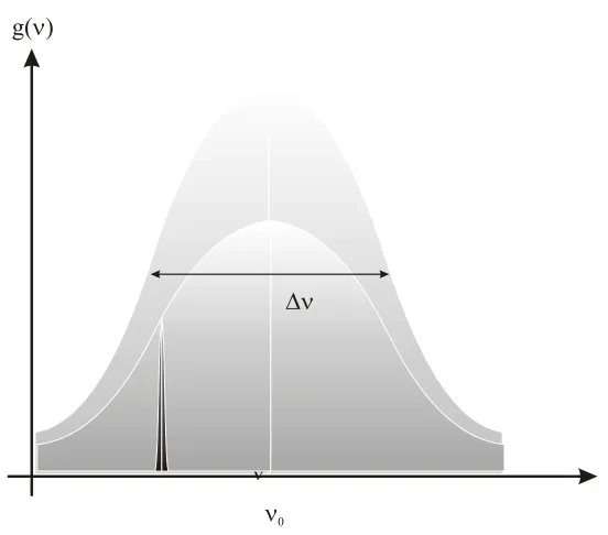
Figure 2.2 Graph showing the Lorentzian distribution of a homogeneously broadened laser gain as a function of frequency.
In the steady-state therefore, the gain of this lasing mode will equal the losses due to the laser cavity, giving it a net gain of unity and all the other axial modes will have a lower stimulated emission cross-section and therefore have gains lower than the threshold of the laser. However, due to spatial-hole-burning, causing a spatially inhomogeneous gain distribution, a laser can operate on many axial modes, even when the laser transition itself is homogeneously broadened. This behaviour is generally associated with standing-wave cavities with a sinusoidally varying axial intensity [2].
The mechanism behind spatial-hole-burning is that different frequencies have their standing nodes in different locations, they will access gain from different regions along the length of the laser rod and, as a result of saturation, the spectral distribution of the gain will become inhomogeneous, typically resulting in several
ν0
g( )ν
28 axial modes lasing simultaneously as they independently access gain from different regions.
2.2.3 Techniques for single-frequency operation
Numerous methods have been employed to obtain single-frequency operation of a laser[3-7] which fall into two main categories: Firstly, techniques which incorporate a strong frequency discriminating element (e.g. such as an etalon) within the laser cavity in order to suppress adjacent modes from oscillating and secondly, techniques which avoid or reduce spatial-hole-burning. Whilst a frequency selective element will reduce the effect of spatial-hole-burning, it will still be present to some degree and any unused gain at the nodes of the stand-wave laser will lead to an overall reduction in efficiency of that laser. Avoiding or significantly reducing the effects of spatial-hole-burning is less straightforward, but leads to more robust and reliable single-frequency operation.
One of the most popular approaches for reducing spatial-hole-burning and hence achieving robust single-frequency operation is to employ a unidirectional ring-laser configuration. As the beam of the ring-laser cavity is a travelling-wave, spatial-hole-burning is dramatically reduced with only a small standing wave contribution due to reflections from imperfect AR coatings. Ring-lasers have the disadvantage of adding extra complexity to cavity design and the need to introduce an optical-isolator (producing a direction dependent loss within the cavity) in order to enforce unidirectional operation. Optical isolators are generally designed to have low losses so as to not inhibit the performance of the laser (by adding to overall cavity loss), and, even with the need for a ring path within the cavity, a great deal of flexibility in cavity design can be maintained. These points can be demonstrated in monolithic ring lasers [8] and rhomb ring lasers [9]. However, in order to obtain optimised single-frequency operation, one has to ensure that the reflections for the end surfaces of any intracavity components do not overlap with the gain region within the laser rod.
29 transmission in the forward direction to 99% transmission in the reverse). This small loss is enough to enforce uni-directional and hence single-frequency operation. The two effects that can be used in optical isolators are the acousto-optic effect [10] and the Faraday effect [11]. In acousto-optic modulators, an ultrasonic wave is launched into a block of transparent material, typically fused silica. The transparent material acts like an optical phase grating when an ultrasonic wave passes through it. This is due to the photoelastic effect, which couples the modulating strain field of the ultrasonic wave to the optical refractive index of the transparent material. The result is a travelling grating within the material with a period equal to the acoustic wavelength and an amplitude proportional to the sound amplitude. If a beam of light is incident on this grating, a portion of its intensity will be diffracted out of the beam into one or more discrete directions.
Figure 2.3 Diagram showing a laser beam scattered off the travelling acoustic waves of an acousto-optic modulator. Not to scale (acoustic wavelength is smaller than the beam diameter).
When the frequency of the acoustic wave is raised and its interaction length is increased, the higher order diffracted beams of light are eliminated and the 0th and 1st order beams become predominant (see Figure 2.3). This condition is known as Bragg scattering. For an acousto-optic modulator length l, refractive index n, with an acoustic wavelength ∆, interacting with an optical wavelength λ, the condition for Bragg scattering to occur is:
2
lλ ∆
[2.7]
Θbragg
Acoustic Wave
Incident Beam Transmitted Beam
30 In the Bragg regime the optical and ultrasonic beams are slightly offset from normal incidence to interact at the Bragg angle Θ (see Figure 2.3):
sin 2
λ
Θ = ∆
[2.8]
Where it should be noted that λ, ∆ and Θ are all measured inside the medium, that is λ=λ0/n. An acousto-optic modulator using Bragg reflections from an acoustic travelling wave can be used within a ring laser configuration to provide non-reciprocal loss. Two independent mechanisms exist for acousto-optically induced unidirectional laser operation, namely the intrinsic and feedback mechanisms.
The intrinsic nonreciprocity of a travelling-wave acousto-optic modulator is a result of the fact that the plane of the moving acoustic wave fronts is at an angle to the optical axis of the laser beam. Looking at the incident laser beams in the forwards and backwards propagating directions (Figure 2.3) the acoustic wave is either travelling towards or away from the incident wavefront. Viewed from the system of the acoustic travelling wave, the incident light will see a small Doppler-shift i.e. in the backwards direction the acoustic wave-front appears to have a higher frequency than the forward direction and hence a smaller wavelength. This results in a small difference in the Bragg angle for the forwards and backwards propagating light beams given by:
2 S
Bragg n
c
ν
∆Θ ≈
[2.9]
When the AOM is tilted slightly away from the Bragg angle, the diffraction efficiency falls off as a sinc2 function, which is much broader than the difference in
the Bragg-angle:
2 1
0 sin
2
I I
∆Θ
=
[2.10]
31 there exists a second method based around the feeding-back of the diffracted beams. Under the appropriate conditions, this feedback technique can yield much higher loss-differences than that of the intrinsic technique alone. The feedback mechanism relies on the beam frequency ν, when diffracted, being shifted by the acoustic travelling wave frequency νS. the beams in the forward propagating direction (figure
2.3) are shifted down in frequency ν - νS, whilst in the opposite direction, the beam is
shifted up ν + νS. A basic schematic of the feedback oscillator can be seen in figure
[image:32.595.195.477.245.534.2]2.4:
Figure 2.4 Diagram showing acousto-optic travelling wave feedback technique using external ring feedback resonator.
The laser resonator is formed using the mirrors A, B and C. The external feedback resonator is formed by mirrors D, E and F and is fed back into the acousto-optic modulator where it is partially diffracted back into the path of the laser. The path that was originally shifted down to ν - νS will be shifted up to the original laser
frequency so that it can interfere with the main beam. Light in the opposite direction is shifted up to ν + νS and shifted down when fed back into the laser resonator. The
feedback path length is practically the same in both directions, however they experience different round-trip phase shifts causing an interferometrically produced
Feedback Resonator
Laser Resonator
AOM
A B
C E
D F
( - )ν νS
( + )ν νS
(-) (+)
32 loss-difference, meaning that it can be much larger for a given diffraction efficiency within an acousto-optic modulator than for the intrinsic case[10]). Even though the feedback technique produces larger loss-differences however, the cavity alignment is unstable and complicated to implement. An attractive solution to this problem is to use the mirrors of the laser resonator itself to feedback through the diffracted light (self-feedback technique) since any given change in the cavity length will effect not only the laser but the feedback path as well. It has been observed that this approach will improve the stability of the laser to within two to three orders of magnitude compared to the external feedback resonator, however, the loss of the feedback path will be greater than that of the external resonator due to the number of round trips of each cavity, leading to a higher insertion loss and reduced loss-difference between the opposing cavity directions. There needs to be only a very small loss-difference within a laser ring cavity to ensure unidirectional operation, however, acousto-optic modulators are also especially useful if Q-switching is required. Hardman et al [12], demonstrated a Nd:YLF ring laser that utilized the 1st order diffracted beam from the acousto-optic modulator (intrinsic technique) as the output coupling. In this case the AOM allowed Q-switched operation of the laser and also allowed optimised output coupling in a cw regime.
Optical isolators based of the Faraday effect can give a much higher loss-difference than acousto-optic devices at the expense of higher insertion losses due to absorption in the Faraday medium and any incurred anti-reflection coating losses. However, in the cases where a higher loss-difference is needed, they are essential. A typical Faraday rotator optical isolator consists of the Faraday rotator itself with an optical rotator (half-wave plate) and a polariser. In the forward direction, the Faraday rotator, rotates the polarisation of the laser mode, which is then rotated back by the optical rotator to its original position, it then passes through the polariser with the correct orientation for maximum transmission. In the reverse direction, because of the non-reciprocity of the Faraday rotator, the rotations add instead of cancelling, thus causing the light in the backwards direction to see losses at the polariser. In order to calculate the average loss per round trip, it is useful to analyse the laser cavity in question with Jones matrices to find the eigen-polarisations of the resonator (i.e. the state for which the polarisation state is conserved after one round trip).
33 between the laser and the pump source can lead to changes in the loss-difference within the cavity, this in turn can lead to mode-hopping due to fluctuations in the optical cavity length and higher order mode oscillation at higher pump powers. Because of this, at higher pump powers, instabilities in single-frequency operation can occur and therefore, careful design considerations must again be made in order to maintain robust and reliable operation.
2.2.4 Diode pump sources
As diode based pump source output powers have been increased over the last decade, thermal loading of laser gain materials has led to increased problems related to power scaling. In the previous section we mentioned the astigmatic output from low power diode devices that could be coupled into a laser material using conventional optics. However, at higher powers, more complex systems are needed due to the highly elliptical output beam and highly asymmetric diffraction properties of the high power diode lasers. Due to improvements in fabrication techniques in the 1980’s, diode devices became both reliable and efficient with early devices (typical dimensions of 1µm × 5µm) producing output powers of up to ~200mW. Multi-stripe laser devices were then developed to reduce the risk of facet damage, producing up to a few watts of output power from a device with overall dimensions of around 1µm × ~200µm. Limited by thermal effects, the construction of even longer arrays of these low-power multi-stripe devices lead to devices that are known as diode-bars, with even higher output powers.
34 Thus, focussing the output to the small beam sizes required for efficient end-pumping of solid-state lasers is very difficult to achieve [1].
Table 2.1 Example specifications of Coherent diode pump sources s/n 10243063
The fact that the output from a diode bar is nearly diffraction limited M2~1 in
one plane and is M2~2000 in the other, has a serious limitations on the optimised focus spot that can be achieved in the array plane using conventional optics. Using equation 2.6 from the previous section, we can calculate that the optimal focussed spot in the array plane for a resonator with a circular mode (M2~2000) would be ~1.3mm and ~10mm in the x and y planes respectively. Because of this the threshold from equation 2.1 would be respectively larger and poor mode matching between the laser mode and the pump would result.
Specification 808nm 10243063 808nm 10243063
Output Power (W) 40 60
Centre Wavelength (nm) 808 808
Centre Wavelength Tolerance (nm) ±2.5 ±2.5
Wavelength Temperature Coefficient (nm/0C) 0.28 0.28
Spectral width (FWHM) (nm) <0.25 <0.25
Array Length (mm) 10 10
No. of emitters 19 49
Emitter Size (µm) 150×1 100×1
Emitter spacing (µm) 500 200
Slope efficiency (W/A) 1.1 1.1
Conversion Efficiency (%) >45 >45
Threshold Current (A) <10 <15
Operating Current (A) 45 60
35
2.2.5 Diode beam delivery schemes for high-power diode pump sources
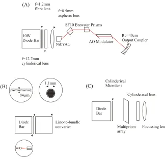
[image:36.595.167.491.211.525.2]Various diode-bar beam delivery systems have been demonstrated over the past few years utilizing, for example, cylindrical and aspheric lenses or multi-prism arrays [13-16], which will allow the user to focus to smaller spot-sizes at the cost of large reductions in brightness from the device.
Figure 2.5 Diagram showing three examples of high-power diode coupling techniques, (A) using a cylindrical and aspheric lens [13], (B) fibre-coupled diode bar [17] and (C) multiprism array rotating
output from each emitter by 900 [16].
The solution adopted for the purposes of this research was to use a simple beam-delivery technique that chops and stacks the output of the diode effectively equalising the beam quality of the diode-bar in both orthogonal planes with only a small decrease in brightness. This scheme, known as the two-mirror-beam-shaper [18], converts the collimated output from a diode bar into a stack of beams, one from each emitter in the diode-bar array. The outcome of this is that the diode-bars
(A) f=1.2mm fibre lens
f=12.7mm cylinderical lens
f=8.5mm aspheric lens
Nd:YAG
SF10 Brewster Prisms
AO Modulator
Rc=40cm Output Coupler 10W
Diode Bar
Diode
Bar Line-to-bundleconverter 84 mµ
1.1mm
(B)
Diode Bar
Cylinderical Microlens
Multiprism array
Cylinderical lens
Focussing lens
36 original output (Mx2 ~ 1, My2 ~ 2000), is equalised so that the beam quality M2 in the
[image:37.595.249.426.131.382.2]x and y planes is ~ 70.
Figure 2.6 Diagram showing the two mirror beam shaper [18].
By beam-shaping the output from the diode in this way (Figure 2.6) we can focus the pump light to a smaller spot size, keeping the ‘l M2’ product low. This improved beam quality allows us to focus the output from the diode bar to a relatively small beam size, with a long Rayleigh range, z0 which is calculated using
the following expression:
2 ( , )
0 2
( , )
P x y
x y
nw z
M
π
λ =
[2.11]
The beam-shaped output from a diode bar is therefore ideal for end pumping solid-state and fibre laser systems. In addition, the shaped output also allows the light from the diode to be efficiently coupled into an undoped optical fibre with a relatively small core diameter, allowing us to efficiently couple the light from the diode to a laser system without the need for any expensive intermediate optics that would require critical alignment. In the case of these experiments, the pump delivery
HR
HR Outputbeams Output beams HR
HR
A B Incident
beam
A B
Plan view
Side view
x z
y
z x
37 fibre was undoped silica fibre of 250µm diameter core, with an N.A. = 0.22 and we typically measured coupling efficiencies of up to 85%.
Based on the focussing scheme described in this section, it is possible to estimate the threshold and output power of an end-pumped solid-state laser using equations 2.1-2.5. From equation 2.6, the minimum effective pump beam size (assuming M2 in the x/y planes is ~70) is decreased dramatically and becomes dependent on length of the laser gain medium. Hence, it can be calculated that for an Nd:YAG laser operating at 1064nm with an output coupler transmission of 10% and a roundtrip loss of 2%, the threshold is ~0.2W. By making ηPL ~ 1and using wL = wP
(~ 250µm), a maximum TEM00 output power of ~8W for 15W of incident pump
power can be achieved. Due to the small threshold in relation to the maximum available pump power therefore, it could also be possible to operate the laser on much lower gain transitions, as well as many three-level transitions, proving that the beam-shaper route to diode-end-pumping offers a very attractive route to power-scaling solid-state lasers.
2.3 Thermal effects
2.3.1 Heat Generation
... Due to the simplicity of mounting and heat sinking, copper mounted edge cooled laser rod geometries have been adopted as a means to dissipate heat from the laser rod. It is the heat extraction from a laser rod that causes a non-uniform temperature gradient across its radius under end-pumped conditions. An expression can be derived for the resulting temperature distribution for an edge cooled rod of radius ra and length l mounted in a heatsink that is maintained at a constant temperature and end-pumped by a diode laser of incident pump power PP ,[12]
38 ...
Figure 2.7 Simple diagram showing the edge-cooled rod of radius ra and length l.
It can be shown that the heat flux h(r,z) under steady state conditions must satisfy the general equation 2.12:
. ( , )h r z Q r z( , )
∇ =
[2.12]
Where Q(r,z) is the absorbed pump power converted to heat per unit volume.
If we now make the assumption that the temperature at the edge of the laser rod is equal to the temperature of the heatsink T(r), from equation 2.12 we can show that the net radial heat flow from the thin disk of radius r and thickness ∆z at axial position z [19] by
0
2 ( , ) ( , )2
z z r
z
zh r z Q r z rdrdz
π∆ = +∆
∫ ∫
π[2.13]
This expression neglects axial heat flow within the laser rod. Making further assumptions that the ground state is not significantly depleted, the pump has a transverse Gaussian intensity profile and neglecting diffraction, then Q(r,z) can be written as:
( , ) P P( , )
Q r z =ρα I r z
[2.14]
where
2
2
2 2
( , ) P exp
P P
P P
P r
I r z z
w w α
π
−
= −
[2.15]
is the pump intensity, ρ is the fraction of absorbed pump power converted to heat, wP
in the 1/e2 radius of the pump beam, αP is the pump absorption coefficient. By
T(r)
l
ra
r z
39 substituting eq.2.14 into eq.2.13, we can obtain the expression for the radial heat flux h(r,z):
2 2
1 exp( 2 / )
( , ) exp( )
2
P P P
P
P r w
h r z z
r
α ρ α
π
− −
= −
[2.16]
So, it follows that the temperature difference, ∆T(r,z) inside the crystal can then be calculated as follows:
1
( , ) ( , ) ( , ) ( , )
a
r
a
C r
T r z T r z T r z h r z dr
K
∆ = − =
∫
[2.17]
Where KC is the thermal conductivity. From equation 2.17, we can therefore produce
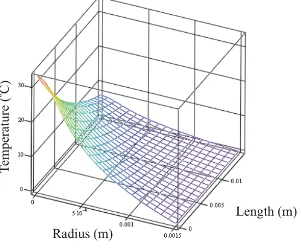
[image:40.595.179.474.420.665.2]a 3-dimensional picture of the temperature distribution within a laser rod. In the following example a 3mm diameter, 15mm long Nd: YLF laser rod is used, Kc = 6.3Wm-1K-1, αp = 107m-1, wp= 250µm, the incident pump power is 20W and ρ= 0.24 assuming quantum defect heating only.
Figure 2.8 Temperature distribution in example 3x15mm Nd: YLF laser rod with Kc=6.3Wm-1K-1, αp
~107m-1, w
p=250µm, Pp=20W and ρ=0.24. C
Radius (m)
Length (m)
Te
mperature (
C
)
40 It can be seen from this figure 2.8 that there is a large radial variation of temperature. The temperature is highest at the centre front end and decays exponentially towards the opposite surface. It is this radial variation of temperature that leads to the main thermal problems of thermal lensing, thermally-induced birefringence and ultimately, stress-fracture.
2.3.2 Thermal Lensing
There are three contributing mechanisms to thermal lensing: Firstly, the temperature dependence of refractive index. Secondly, the mechanical stresses within the laser rod brought about by the temperature gradient within the rod as it undergoes cooling via the heatsink – leading to a stress-induced change in refractive index. Finally, the temperature distribution causes a physical distortion of the end faces of the rod (i.e. end-face bulging).
The model given in the previous section (2.3.1) can be used to derive an expression for the thermal lens power due to the temperature dependent refractive index [12, 20]. The relative importance of this contribution depends on the thermo-optical and thermo-mechanical properties of the laser material. In the case of Nd:YAG lasers, the refractive index variation with temperature accounts for 80% of the contribution to thermal lensing, however for other materials such as Nd:YLF it may be necessary to take into account the contributions to the thermal lens due to the end-face curvature of the laser rod and the stress dependence of the refractive index as well. Here we merely quote the final expression in terms for thermal lens power, where fth is the
thermal lens focal length:
2
2 ( )
( )
C th
P abs
K r f r
dn
P s r
dT
π ρη
=
[2.18]
where
0
2
( ) ' ( ') '
r
P P
s r r I r dr
P
π
=
∫
41 The thermal lens generated within a laser rod can hinder the power scaling of diode-end-pumped solid-state lasers in two ways. Firstly, the lens can affect the mode size of the laser within the resonator leading, at higher pump powers, to poor overlap between the laser mode and the pump mode (allowing the possible lasing of higher order transverse modes which in turn start depleting the gain, restricting single-frequency operation and degrading beam quality) so it becomes essential to have accurate knowledge of how the thermal lens varies with pump power. This leads to difficulties in maintaining TEM00 operation over the entire range of pump powers
available. Secondly, in general, it can be seen from equation 2.18, the focal length
fth(r) varies radially. This is a consequence of the non-uniform transverse intensity
profile of the pump beam and hence the non-parabolic phase aberrations that result. Thus, a rapidly varying focal length with radial position implies a highly aberrated thermal lens which will severely degrade laser beam quality. Thus a pump beam with a relatively high on-axis intensity compared to its wings will lead to both a strong and very aberrated thermal lens. As an example we can consider the special cases of
top-hat and Gaussian pump beam profiles. For a pump beam of radius wp and a
uniform intesity Ip=Pp/πwp2 for r ≤ wp and Ip = 0 for r > wp, we can obtain the following expression for thermal lens focal length:
2
2
2
( ) ( )
2
( ) ( )
C P
th P
P abs
C
th P
P abs
K w
f r r w
dn P
dT
K r
f r r w
dn P
dT
π ρη
π ρη
= ≤
= ≥
[2.20]
From the equations in 2.20 it can be seen that the thermal lens has no high-order phase aberrations within the pumped region (i.e fth a constant value independant of r) but is highly aberatted outside the pump region r > wp where fth is proportional to r2. This indicates that a laser beam mode size wL < wP will experience no degradation in
42 A Gaussian pump beam profile however, with intensity
2
2 2
2 2
( ) P exp
P P P P r I r w w π − = ,
will produce a corresponding expression for thermal lens focal length:
2 2 2 2 2 2 (0) ( ) 2 1 exp (0) th th P P C P th P abs r f f r r w w K w f dn P dT π ρη = − − = [2.21]
Where fth(0) is the on axis focal length (i.e. at r = 0). In contrast with the top-hat beam profile, it can be seen from equation 2.21 that a Gaussian pump beam leads to a much more highly aberrated thermal lens which is in fact two times stronger on axis for the same pump spot and power. Therefore, a Gaussian pump mode profile, whilst providing better mode overlap with the fundamental transverse laser mode leading to lower laser threshold and increased slope efficiency than a top-hat beam, does have the disadvantage of leading to more pronounced beam distortion and degradation in beam quality.
In practice, a typical focused beam from a high-power diode source will have a transverse intensity profile that lies somewhere between the Gaussian and top-hat examples and precise control of the pump beams transverse mode profile is difficult leading to a reduction in available pump power and brightness (sections 2.2.4 and 2.2.5). However, a limited degree of reshaping of the pump beams profile to reduce the aberrated nature of the thermal lens, and hence decreased beam distortion can be achieved by coupling the pump light into a multimode fibre (section 2.2.5).
The strength of the on-axis thermal lens contribution due to temperature dependence of the refractive index for three common laser materials Nd:YAG, Nd:YVO4 and Nd:YLF, assuming a Gaussian pump beam mode profile can be
calculated as a useful comparison of the various material properties. Using the same example as in section 2.3.1, where wp=250µm, ρ=0.24, PP=20W, the on-axis thermal
43
Nd:YAG Nd:YVO4 Nd:YLF
dn/dT (K-1) 7.3×10⁻⁶ 3.9×10⁻⁶ -2.0×10⁻⁶
KC(Wm-1K-1) 13 5.3 6.3
fth(0)(mm) 72 55 -129
Table 2.2 Table showing the calculated on axis thermal lens for Nd:YAG, Nd:YVO4 and Nd:YLF using equation 2.21 where wp=250µm, ρ=0.24, PP=20W.
In table 2.2 it can be seen that the Nd:YLF produces a comparatively longer negative thermal lens focal length (on the 1053nm line) due to the small negative change in refractive index. The positive contribution of the lens produced by the bulging end-faces of the laser rod in the case of Nd:YAG and Nd:YVO4 will lead to the thermal
lens strength increasing, whereas it must be noted that the same contribution to Nd:YLF will lead to the thermal lens becoming weaker still. This calculation therefore implies that under the same pumping conditions, Nd:YLF will experience a thermal lens that will contribute comparatively less to beam distortion and the degradation of beam quality than Nd:YAG and Nd:YVO4 respectively.
An important consideration is what effect on the TEM00 laser operation is
imposed by thermally induced lens aberrations. The degradation of beam quality which results from the propagation of light through an aberrated thermal lens can be compared to the effect of quartic phase aberration in a standard spherical lens analysed by Seigman [21], in that we can determine the effect of a Gaussian beam passing through a highly aberrated thermal lens generated by a pump beam with intensity profile IP(r). According to [21], a laser beam with a Gaussian intensity profile and initial beam quality Mi2 after propagating through a lens of focal length f will produce a phase distortion ∆ø(r):
2
4 4 2
( )
2
r
r C r
f
π φ
λ
∆ = −
[2.22]
It suffer degradation in beam quality such that the resultant beam quality factor Mf2 is given by:
( ) ( )
2 22 2 2
f i q
M = M + M
44 Where Mq2 is due to the quartic phase aberrations of the lens and is given by:
4
2 8 4
2 L q C w M π λ = [2.24]
wL is the beam radius and C4 is the quartic phase aberration coefficient. In general, a
thermal lens will produce a more complicated phase distortion than a standard optical lens, but restricting the consideration to situations where wL < wP , so that higher
order terms than the quartic can be neglected, the resulting expression for the beam quality degradation of the thermal lens Mq2 is given by:
2 2 2 2 abs L q C dn w B dT M K ρη π λ = where 2 2
0.5 P( ) / at 0
B= d I r dr r=
[2.25]
Thus from equation 2.23 and 2.25 we can estimate the degradation in beam quality which results after a passage of the laser beam through an aberrated thermal lens, generated by a pump beam with an arbitrary intensity profile.
For a top-hat pump beam B = 0 so there is no degradation in beam quality, however, for a Gaussian beam profile, 4 / 4
p P
B= P πw and hence
4 2 4 2 p abs L q p c dn P w dt M w K ρη λ = ⋅ [2.26]
This expression shows that in addition to the dependence on power dissipated as heat, thermo-mechanical and thermo-optical properties of the laser material, the degradation in beam quality also depends strongly on the ratio of laser beam radius to pump beam radius. Hence, if wL<<wP, then the beam quality is less influenced by


![Figure 2.6 Diagram showing the two mirror beam shaper [18].](https://thumb-us.123doks.com/thumbv2/123dok_us/8518610.352358/37.595.249.426.131.382/figure-diagram-showing-mirror-beam-shaper.webp)