IJEDR1402101
International Journal of Engineering Development and Research (www.ijedr.org)1926
Analysis of Sub synchronous Resonance Using
Simulation of IEEE FIRST BENCHMARK Model
1
Avani H. Ranpariya,
2Parth N. Dave
1P.G. Student (Electrical Power System), 2P.G. Student (Electrical Power System) Electrical Engineering Department,
V. V. P. Engineering College, Rajkot, India.
1[email protected], 2[email protected]
________________________________________________________________________________________________________
Abstract - The benchmark model for the study sub synchronous resonance is presented by IEEE committee. Here IEEE First benchmark system for Sub synchronous Resonance Analysis is simulated using MATLAB. The Oscillations because of Sub Synchronous Resonance are observed between turbine generator and various turbine shafts. For reducing oscillations or to mitigate Sub synchronous resonance phenomena FACTS device (Flexible AC transmission system) is used. This paper represents analysis of sub synchronous resonance using MATLAB Simulation.
Index Terms –SSR, series compensation, transient torque, synchronous machine, torsional oscillation
________________________________________________________________________________________________________
I.INTRODUCTION
Series capacitor compensation in AC transmission systems is an economical means to increase load carrying capability, control load sharing among parallel lines and enhance transient stability. However, capacitors in series with transmission lines may cause sub synchronous resonance that can lead to turbine-generator shaft failure and electrical instability at oscillation frequencies lower than the normal system frequency. Therefore, the effects of SSR must be fully understood and analyzed when planning series capacitor compensation in power systems. The main concern with SSR is the possibility of shaft damage from torsional stresses. Damage can result from the long term cumulative effects of low amplitude torsional oscillations or the short term effects of high amplitude torques. Typically, hydro units have mechanical parameters that are less prone to SSR problems than thermal units [3].
Sub synchronous oscillations were first discussed in 1937 and until 1971, shaft torsional oscillations were neglected. Two shaft failures at the Mohave Generating Station in Southern Nevada led to the understanding and development of the theory of interaction between series capacitor compensated lines and the torsional modes of steam turbine-generators [1]. After the second shaft failure at Mohave, the utility industry devoted considerable effort to the analysis and suppression of the SSR phenomenon.
II.TYPESOFSSRINTERACTION
There are three types of SSR interactions which are Induction Generator Effect, Torsional Interaction Effect and Transient Torque Effect.
A. Induction Generator Effect
Three phase current at sub synchronous frequency can result due to a nearby network disturbance. When the sub synchronous frequency currents flow through the generator armature, they view the synchronously rotating rotor‟s circuit as negative resistance. If this negative resistance is greater than the sum of the armature and network resistance, the electrical system is self-excited. Such self-excitation would be expected to result in excessive voltage and current [2]
B. Torsional Interaction
Torsional interaction occurs when the induced sub synchronous torque in the generator is close to one of the torsional natural modes of the turbine generator shaft. When this happens, generator rotor oscillations will build up and this motion will induce armature voltage components at both sub synchronous and super synchronous frequencies. Moreover, the induced sub synchronous frequency voltage is phased to sustain the sub synchronous torque. If this torque equals or exceeds the inherent mechanical damping of the rotating system, the system will become self-excited. This phenomenon is called "torsional interaction."
C. Transient Torque
IJEDR1402101
International Journal of Engineering Development and Research (www.ijedr.org)1927
current. Currents due to short circuits, therefore, can produce very large shaft torques both when the fault is applied and also when it is cleared. In a real power system there may be many different sub synchronous frequencies involved and the analysis is quite complex.III.IEEEFIRSTBENCHMARKMODEL
The single line diagram of a Single Machine Infinite Bus system given by IEEE committee for SSR study is shown in fig 1
.
Fig. 1: Single line Diagram for IEEE first benchmark system
The circuit parameters are expressed in per unit on the generator MVA rating at 60Hz. Reactance are proportional to frequency, resistances are constant. The infinite bus is a 3-phase 60 Hz voltage source with zero impedance at all frequencies.
A. Synchronous Machine Model
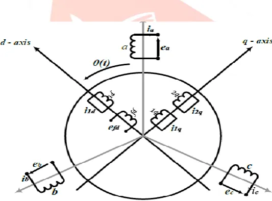
Simple model of synchronous generators are not suitable for accurate description of the power results in time invariant machine equations. So we consider machine in the park reference frame which is rotor reference frame with one damper winding in D-axis and two damper winding in Q-axis shown in fig 2
Fig. 3: Schematic diagram of conventional synchronous machine
This model shows three phase armature winding on stator i.e. a, b and c and four winding on the rotor including field winding „f‟. The damper winding is represented by equivalent damper circuit in the direct axis and quadrature axis: 1d on d-axis and 1q and 2q on q-axis.
Two equivalent rotor circuits are represented in each axis of the rotor - F and D in the d-axis, and G and Q in the q-axis, with positive current direction defined as the direction causing positive magnetization of the defined d- and q-axis direction[4], respectively. Synchronous machine operation under balanced three-phase conditions is of particular interest for SSR analysis.
In first IEEE benchmark system circuit parameters are expressed in per unit on the generator base of 892.4 MVA, 60 Hz frequency. Reactance is proportional to frequency and resistances are constant. This system configuration corresponds to the Navajo Project‟s 892.4 MVA, 500 kV transmission systems.
B. Multi Mass Model of the Turbine- Generator shaft
IJEDR1402101
International Journal of Engineering Development and Research (www.ijedr.org)1928
Fig. 4: Mechanical structure of six mass FBM systemsFrom fig 3 the torques acting on the generator mass is:
Generator:
Input torque (1) Output torque (2)
Damping (3)
Low pressure turbine B:
Input torque (4) Output torque (5) Damping (6)
Similarly all other masses torque equation can be derived.
IV.SIMULATION AND RESULTS
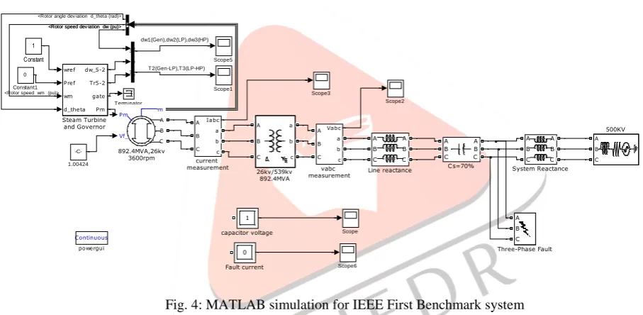
MATLAB simulation for IEEE first benchmark system is shown in fig 4
Fig. 4: MATLAB simulation for IEEE First Benchmark system
The machine and circuit parameters are real value taken from the Navajo Project [Appendix]. For the transient case, single phase to ground fault is applied as shown in figure 4 for duration of 80 msec(4 cycle) from 0.1 seconds to 0.175 seconds. In the reference paper, fault reactance is 0.04 p.u. and it is adjusted to produce a capacitor transient voltage approaching the lower gap setting.
Capacitor voltage, Generator current, Generator Electrical Torque, Shaft Torque, speed is plotted for the time duration 1.0Second.
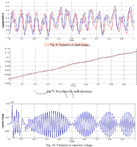
Fig.5 shows variation of Electrical torque of the synchronous generator. It is clear that the torque is not constant for some times after application of fault. That shows the electrical transmission network resonant frequency matches one of the natural modes of the multimass turbine. Fig. 6 shows the shaft torque. From the graph, it is seen that the shaft torque oscillates due to SSR phenomena. Fig. 8 shows the variation of voltage across the capacitor due to SSR.
Fig. 9 shows the variation of the machine current in per unit. From the graph, it is seen that the machine phase current is oscillatory. T2(Gen-LP),T3(LP-HP) dw1(Gen),dw2(LP),dw3(HP) Vabc A B C a b c vabc measurement Continuous powergui Iabc A B C a b c current measurement 1 capacitor voltage A B C A B C Three-Phase Fault Terminator A B C A B C System Reactance In1 In2 In3 dw_123 T_23 wref Pref wm d_theta dw_5-2 Tr5-2 gate Pm Steam Turbine and Governor Scope6 Scope5 Scope3 Scope2 Scope1 Scope A B C A B C Line reactance 0 Fault current A B C A B C Cs=70% 0 Constant1 1 Constant Pm Vf_ m A B C 892.4MVA,26kv 3600rpm A B C 500KV A B C a b c 26kv/539kv 892.4MVA -C-1.00424 <Rotor angle dev iation d_theta (rad)>
<Rotor speed wm (pu)>
IJEDR1402101
International Journal of Engineering Development and Research (www.ijedr.org)1929
Fig. 7: Variation of electromagnetic torqueFig. 8: Variation of shaft torque
Fig. 9: Waveform for shaft speed(pu)
IJEDR1402101
International Journal of Engineering Development and Research (www.ijedr.org)1930
Fig. 10: Variation in system currentV.CONCLUSION
Sub synchronous resonance effect is studied using IEEE First Benchmark system and the results have been investigated. It is observed that series compensation produces Sub synchronous resonance, during fault conditions. Sub synchronous Resonance Phenomena is simulated by exciting the torsional modes with single phase to ground fault for duration of four cycles. Result shows that Electromagnetic torque and voltage across the capacitor are highly distorted
Appendix
Network parameter of the system is as follows:
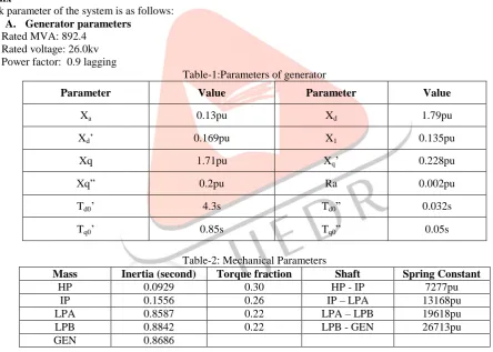
A. Generator parameters
Rated MVA: 892.4
Rated voltage: 26.0kv
Power factor: 0.9 lagging
Table-1:Parameters of generator
Parameter Value Parameter Value
Xa 0.13pu Xd 1.79pu
Xd‟ 0.169pu X1 0.135pu
Xq 1.71pu Xq‟ 0.228pu
Xq” 0.2pu Ra 0.002pu
Td0‟ 4.3s Td0” 0.032s
Tq0‟ 0.85s Tq0” 0.05s
Table-2: Mechanical Parameters
Mass Inertia (second) Torque fraction Shaft Spring Constant
HP 0.0929 0.30 HP - IP 7277pu
IP 0.1556 0.26 IP – LPA 13168pu
LPA 0.8587 0.22 LPA – LPB 19618pu
LPB 0.8842 0.22 LPB - GEN 26713pu
GEN 0.8686
Transformer parameter
Rated MVA : 892.4 Voltage rating : 26/539kv Delta/star grounded R = 0.00792 pu X = 0.14 pu, X0 = 0.14 pu
Transmission line parameter
R = 0.02pu, X = 0.50pu
0 0.1 0.2 0.3 0.4 0.5 0.6 0.7 0.8 0.9 1
-1.5 -1 -0.5 0 0.5 1 1.5
Time
Curre
IJEDR1402101
International Journal of Engineering Development and Research (www.ijedr.org)1931
Series capacitor
C = 0.371pu
Infinite bus
Voltage: 500kv, Phase angle: 0
REFERENCES
[1] IEEE SSR Working Group, “First Benchmark Model for Computer Simulation of Subsynchronous Resonance”, IEEE Transactions on Power Apparatus and Systems, Vol. PAS-96, no. 5, September/October 1977.
[2] IEEE Committee Report, “Rearer‟s Guide To Subsynchronous Resonance”, Subsynchronous Resonance Working Group of the System Dynamic Performance Subcommittee, IEEE Transactions on Power Systems. Vol. 7, No. 1, February 1992 [3] K.R. Padiyar, “Power System Dynamics Stability and Control”, Indian Institute of Science, Bangalore, 1996.
[4] K. G. Prajapati1, A. M. Upadhyay2 1M.E. [Electrical] Student, 2Associate Professor “Simulation of IEEE FIRST BANCHMARK Model for SSR Studies” IJSRD - International Journal for Scientific Research & Development| Vol. 1, Issue 3, 2013 | ISSN (online): 2321-0613
[5] N.G. Hingorani, L. gyugyi, “Understanding FACTS”:concept and technology of flexible AC transmission systems, New York:IEEE press ,2000