ARRAYED WAVEGUIDE GRATING
YASSIR ABDELRAHIM MOHAMED ABDELAZIZ
A project report submitted in partial fulfillment of the requirements for the award of the degree of
Master of Engineering (Electrical-Electronics & Telecommunications)
Faculty of Electrical Engineering Universiti Teknologi Malaysia
iii
TO
My beloved father and mother. My brothers (Waleed, Hisham and Tariq)
My lovely sister (Hiba). My Uncles and Aunts.
iv
ACKNOWLEDGEMENT
First of all, I thank ALLAH SWT for giving me the strength and power to finish this thesis. Also I would like to acknowledge my real and deep appreciation to Assoc. Prof. Dr. Abu Sahmah bin Mohd Supa’at for his kindness constant endeavor, guidance, help and encouraging me to work hard towards making a good thesis.
v
ABSTRACT
vi
ABSTRAK
Jika dibandingkan dengan lain-lain kaedah rangkaian komunikasi, rangkaian
vii
TABLE OF CONTENTS
CHAPTER TITLE PAGE
DECLARATION ii
DEDICATION iii
ACKNOWLEDGEMENT iv
ABSTRACT v
ABSTRAK vi
TABLE OF CONTENTS vii
LIST OF TABLES xi
LIST OF FIGURES xii
LIST OF SYMBOLS xv
1 INTRODUCTION 1
1.1 Objective if the project 1.2 Scope of Project 1.3 Statement of Problem 1.4 Project Background
1.4.1 Forms of Photonic Network 1.5 Overview of the thesis
1 3 4 5 7 9
2 OPTICAL COMMUNICATION AND Waveguides 10
viii
2.1.1 Applications 2.1.2 History
2.2.2 Technology 2.2 Fiber Optic System 2.2.1 Transmitters
2.2.2 Fiber 2.2.3 Amplifiers 2.2.4 Receivers
2.3 Wavelength Division Multiplexing and Dense Wavelength Division Multiplexing
2.4 Bandwidth Distance Product 2.5 Limitations
2.5.1 Dispersion 2.5.2 Attenuation
2.5.3 Transmission Window 2.5.4 Regeneration
2.6 Last Mile
2.6.1 Comparison with Electrical Transmission 2.7 Optical Waveguide
2.7.1 Optical Waveguide Structure
11 12 14 15 15 17 18 18 19 21 21 22 23 23 25 25 26 28 30
3 ARRAYED WAVEGUIDE GRATING 33
3.1 Arrayed Waveguide Grating 3.2 AWG Tolerance
3.3 Current Design Process of an AWG (Basic De-multiplexer)
3.3.1 Introduction
3.3.2 Receiver Waveguide Spacing
3.3.3 Free Propagation Region(FPR) Length 3.3.4 Arrayed Waveguide Length Increment
ix
3.3.5 Arrayed Waveguide Aperture Width 3.3.6 Free Spectral Range(FSR)
3.4 Issues Affecting the Performance of the AWG 3.4.1 Crosstalk
3.4.2 Insertion Loss
3.4.3 Polarization Dependent 3.4.4 Pass band Shape
3.4.5 Pass band Position 3.5 Summary 39 40 41 41 42 42 43 45 45
4 ARRAYED WAVEGUIDE GRATING DESIGN 46
4.1 Basic design considerations and design parameters 4.1.1 Wavelength dispersion angle and distance
4.1.2 Free spectral range
4.1.3 The channel spacing and focal length 4.1.4 The maximum number of the wavelength
channels
4.2 Performance parameters 4.3 Design and simulation
4.3.1 General Design Procedure
4.3.1.1 Channel spacing and the number of ports
4.3.1.2 Free spectral range and the diffraction order
4.3.1.3 Length difference 4.3.1.4 Pitches and shift positions 4.3.1.5 Focusing length
4.3.1.6 Number of the array waveguides
x
5 RESULTS, ANALYSIS AND DISCUSSION 56
5.1 Project Methodology 5.2 AWG design Steps
5.3 Design Specifications 5.4 Results
5.4.1 Relation between the waveguide spacing and Crosstalk
5.4.2 The relation between number of channels and diffraction order relation
5.4.3 The relation between Waveguide spacing ∆x and the diffraction order
5.4.4 Relation between focal length of the free propagation region and waveguide spacing relation
5.4.5 Relation between loss non uniformity and the frequency shift corresponding the outermost output waveguide
5.4.5 The relation between the Gaussian parameter σg and the loss non uniformity Lu
5.5 Conclusion 5.6 Future Work
56 59 60 62 62 63 64 65 67 68 69 70
xi
LIST OF TABLES
TABLE TITLE PAGE
1.1 Comparisons of WDM de‐multiplexing technologies 2
2.1 Transmission window brands 24
xii
LIST OF FIGURES
FIGURE NO. TITLE PAGE
1.1 Add drop Multiplexer 6
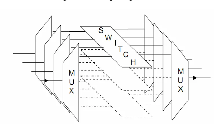
1.2 An Optical Cross Connect (OXC) employing a space division switch for each wavelength.
6
1.3 Passive optical Network 7
1.4 A Long Haul Network, utilizing Add-Drop Multiplexers (ADMs) and Optical Cross Connects (OXCs)
8
2.1 Typical dielectric waveguide 32
3.1 AWG general structure 34
3.2 The Input / Output Free Propagation Region 39
3.3 Passband shape 44
5.1 Flowchart of the methodology of the project 57 5.2 General flow of the design 59 5.3 Waveguide spacing and crosstalk relation 62
5.4 Number of wavelength channel and diffraction order relationship
63
5.5 Waveguide spacing and diffraction order relationship 64
xiii
5.7 Loss non uniformity Lu and the frequency shift corresponding the outermost output waveguide ∆Vlu relationship
67
xv
LIST OF SYMBOLS
λc - Central wavelength
m - Diffraction order
neff - effective refractive index
β - Propagation constant
RFPR - Radius of the free propagation region
∆ƒFSR - Free spectral range
ƒc - Central frequency
θmax - Maximum dispersion angle
Smax - distance to the outermost output waveguide
D - Required dispersion
ds - Displacement of the focal spot on the image plane
df - The change in frequency to cause this displacement
∆ℓ - Length increment
Ňg - Group refractive index
d - Pitch length
nc - Core refractive index
∆x - Waveguide spacing
xvi
Lf - Focal length of the FPR
N - Number of Channels
P - Number of Arrayed Waveguides
ωg - the mode field radius of the central guide
Lu - Loss non uniformity
∆Vlu - frequency shift corresponding the outermost output waveguide
CHAPTER 1
INTRODUCTION
1.1 Objectives of this Project:
In recent years, arrayed waveguide gratings (AWG, also known as the optical phased-array—Phasor, phased-array waveguide grating—PAWG, and waveguide grating router—WGR) have become increasingly popular as wavelength multiplexers/de-multiplexers (MUX/De-MUX) for dense wavelength division multiplexing (DWDM). This is due to the fact that AWG-based devices have been proven to be capable of precisely de-multiplexing a high number of channels, with relatively low loss.
Main features of the M (input) x N (output) AWG MUX/De-MUXes are low
2
Because the fabrication of the AWG is based on standardized photolithographic techniques, the integration of the AWG offers many advantages such as compactness, reliability, large fabrication tolerances and significantly reduced fabrication and packaging costs. The inherent advantages of the AWG also include precisely controlled channel spacing (easily matched to the ITU grid), simple and accurate wavelength stabilization, and uniform insertion loss.
Table.1.1 Comparisons of WDM de-multiplexing technologies
3
The objectives of the project are therefore:
1. Design an arrayed waveguide grating device and its functions.
2. Studying the AWG performance parameters and their effects on crosstalk.
3. Design an arrayed waveguide grating device AWG.
1.2 Scope of the Project:
The project has three aims which are:
1. To study and understand the function, concepts and operation of optical devices used as multiplexing and de-multiplexing techniques for the optical networks.
2. Studying some of the AWG performance parameters such as cross-talk, insertion loss, free spectral range (FSR), and of course the polarization dependence dispersion of the device.
4
1.3 Statement of the Problem:
Optical fiber is a popular carrier of long distance communications due to its potential speed, flexibility and reliability. Attenuation and dispersion problems in fiber, which limit the practical speed and distance of communication, were partially resolved with the advent of the Erbium Doped Fiber Amplifier (EDFA)[1],eliminating problems caused by attenuation. However, the dispersion qualities of an optical fiber still force a compromise between transmission distance and bandwidth, making it necessary to refresh high-speed signals at intervals using opto-electronic repeaters. Solving the dispersion problem in this manner is expensive, due to the additional cost of high-speed electronics, and maintaining and upgrading the link is made more difficult and costly (especially with a buried or under-water link). A more elegant solution is found using Dense Wavelength Division Multiplexing (DWDM), which effectively increases the useable bandwidth in a system without electronic repeaters, and allows realization of a true photonic network.
The recent surge in demand for photonic components that meet economic criteria as well as technical requirements in the telecom and datacom industries has opened the door for novel technologies that enable unique functions and/or unconventional high-yield manufacturing without sacrificing high performance.
The project concerns with following problems:
5
2. The device should be able to retrieve individual channels of different wavelengths at the receiving end.
3. The AWG device is sensitive to the performance parameters such as the crosstalk, diffraction order, loss non uniformity, polarization dependence loss, insertion loss.
1.4 Project Background:
6
devices can be passive, where the signal routing is fixed according to wavelength, or active, as in Figures 1.1 and 1.2, where optical switches are utilized to dynamically route the signals. Both circuits shown are transparent to the data format, can allow bi-directional transfer of information, and function entirely in the optical domain. These functions allow the construction of different transparent optical network topologies, examples of the three major types of these are described in the following subsection.
Fig 1.1 An add drop multiplexer (ADM)
7
1.4.1 Photonic Network:
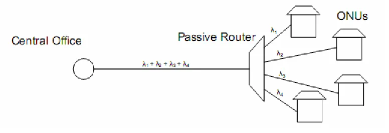
The simplest form of optical network is the point-to-point network. Optical multiplexers and de-multiplexers are required at each end of the link. In this Configuration, DWDM simply increases the number of channels available through one fiber. Passive Optical Networks (PONs) (Figure 1.3) use a wavelength (de)multiplexer as a passive optical router, each wavelength servicing an Optical Network Unit (ONU). This allows the ONUs to share a single long optical fiber link back to the central office (CO) [3].
Fig 1.3: A Passive Optical Network
8
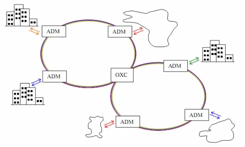
Fig 1.4: A Long Haul Network, utilizing Add-Drop Multiplexers (ADMs) and Optical Cross Connects (OXCs)
9
1.5 Overview of this thesis:
In chapter 1 a quick introduction of the AWG and some background of WDM and DWDM are discussed. The objective, scope of the project and the problem statement are described.
Chapter 2 introduces the optical communications and optical waveguides. It covers the applications, technology, transmitter, amplifiers, receivers, WDM, dispersion and attenuations.
Chapter 3 introduces the AWG device, its operation, functions, and then over viewing the performance parameters that affect the performance of the device.
Chapter 4 taking these performance parameters deeply and finding out their importance.