© 2015, IRJET ISO 9001:2008 Certified Journal Page 2564
VHDL Implementation of MOS based Gas sensor
Preeti Sikarwar
1, Shivani saxena
2,Veerandra kumar
31
M.tech VLSI, Banasthali University, Rajasthan, India
2
Assistant Professor, Department Of Electronics, Banasthali University, Rajasthan, India
3
,Assistant Professor, Department of Electronics, SRM University, Modinagar,India
---Abstract -
Modern gas sensor technology is becoming an important part of our lives. It has been applied within the home (monitoring CO levels from boilers), the workplace (e.g., checking levels of toxic gases) to healthcare (monitoring gases in hospitals). We believe that the combination of CMOS technology with more recent different low power techniques is now mature enough to deliver the exacting demands required to make low-power, low-cost smart gas sensors in high volume and this should result in a new generation of CMOS gas sensors. In this paper, MOS based gas sensor is implemented by using VHDL. The important characteristic of such type of sensor is that, they are made of piezoresistive material where according to gas concentration , the electrical properties of such type of sensors are effected and show sensing behaviour for incoming gas. Additionally, VHDL implementation is easy, simple and further we can do FPGA Implementation where devices are more integrated and easy to use .Simulation tool is ISE Xilinx where results showing from safe to harmful region.Key Words:
VHDL, gas sensors, Sensing element, Sensors
.
1. Introduction
Gas concentration in air can be detected by measuring the resistance change of MOS-type gas sensors. The sensor market is
undergoing continuous development to satisfy the increasing demand for portable sensing applications, mainly for healthcare, environmental and industrial monitoring. In fact, portability significantly widens the spectrum and scenarios of sensing applications but requires optimization of the sensor system at all levels from transducer developments to the design of power-efficient electronic interfaces. Only in this way ,it is possible to attain a system showing the required low-voltage single-supply operation for compatibility with low-form batteries, low power consumption to extend the life of the battery and small size to ensure portability. In the case of remote sensing systems, such as wireless sensor networks (WSNs), the deployment impact must also be minimize[1].
1.1General circuit diagram of gas sensor
© 2015, IRJET ISO 9001:2008 Certified Journal Page 2565
2. Working principle of gas sensor
This schematic of the circuit used to monitor the sensor response and the operating temperature. Two external voltages are applied to sensor .one is used to preheat the sensor VH while second supply (Vsupp) is used to read out output voltage through a
voltage divider. Output is then processed by DAQ. The sensors are heated to a particular temperature by flowing the precalibration current through the heating element. A current flow of 2.8ma.um2 through heating layer is required for an
operating temperature of about 300degree centigrade. This corresponds to a maximum power consumption of about 200mw per chip.
Heater resistance (RH) and Heatervoltage (VH) are different for different gases .At paticular heater voltage VH stable operation
of sensor is found for specific gases. Sensor resistance Rs is changes according to gas concentration for different different
gases. There is no empirical formula between Concentration of gases and sensor resistance (Rs),for again, particular gas with
sensing element is not found yet. According to experiments we can use this relation are shown below :
n
c
k
Ro
s
R
(
)
---1
Where
1. R(s) is the resistance of the film at gas concentration C 2. R0 is the resistance at zero gas concentration
3. K is a sensitivity parameter measurement constant 4. n is a parameter that varies in the range 0.3 to 0.8
5. The positive sign is used for oxidizing gases and the negative sign is for reducing gases
Measured Output voltage (Vout) can be calculated by:
V
R
R
V
inH S
OUT
---2
Where Rs =Sensor resistance.
RH = Heater resistance at particular heater voltage, depend on type of sensor (fixed value).
Vin = requiredcircuit input voltage<= 5V
3.Different gas sensors technologies:
Now a day’s gas sensing technologies are:
1. Metal Oxide Based Gas Sensors 2. Capacitance Based Gas Sensors 3. Acoustic Wave Based Gas Sensors 4. Calorimetric Gas Sensors
5. Optical gas sensors
© 2015, IRJET ISO 9001:2008 Certified Journal Page 2566 3.1 Metal Oxide Based Gas Sensors
In MOS based gas sensor, surface property will be change according to the gas concentration as the sensitive part of these type of sensors are on the surface with piezoresistive material like ZnO,TiO2 etc. Gas concentration in air can be detected by measuring the resistance change of MOS-type gas sensors. Metal oxide sensors are also known as chemiresistors. The detection principle of resistive sensors is based on change of the resistance of a thin film upon adsorption of the gas molecules on the surface of a semiconductor. The gas-solid interactions affect the resistance of the film because of the density of electronic species in the film. The chemical reaction of gases and adsorbed oxygen on the film for e.g. tin dioxide surface varies depending on the reactivity of sensing materials and working temperature of the sensor. Advantages are low cost, short response time, long lifetime, high sensitivity. Limitations of such type of gas sensors are high energy consumption, sensitive to environmental factors.
3.2 Capacitance Based Gas Sensors
They measured the change in dielectric constant of films between the electrodes as a function of the gas concentration. The capacitive sensor relies on inter-digitated electrode structures, which correspond to the two plates of a standard capacitor, to monitor changes of the dielectric coefficient of the film. The simple theory behind it is, if the dielectric constant of the film is lower than that of the analyte, the capacitance will increase and vice versa.
3.3Acoustic Wave Based Gas Sensors
Sound based gas sensors are known as acoustic wave based gas sensor. To launch the acoustic waves, this type of sensors used piezoelectric material either in the thin film form or in bulk form which has one or more transducers on its surface. This type of acoustic waves generated and device resonant frequency has been determined[3]. Depending on that, it is possible to measure properties, processes, or chemical species in the gas phase, liquid phase, vacuum or thin solid films. Advantages are long lifetime, avoiding secondary pollution. Disadvantages are Low sensitivity as compared above.
3.4Calorimetric Gas Sensor
The principle of Calorimetric gas sensors based on change in temperature at catalytic surfaces. It consists of a surface of a film of a catalytically active metal (e.g. Platinum, Palladium or Rhodium).It burns combustible gases. Heat is generated due to the combustion. This heat is balanced by a reduction in the electrical heating power. Thus the power consumption indicates the concentration of gas. Advantages are adequate sensitivity for industrial detection, excellent separation performance and disadvantages are risk of catalyst poisoning and explosion, intrinsic deficiencies in selectivity
3.5 Optical gas sensors
© 2015, IRJET ISO 9001:2008 Certified Journal Page 2567 Table 1: Comparison of Gas sensing Technologies [7]
4.MOS based sensing element
There are different harmful gases which are shown in table2 of having different sensingelements are-
Table2: Harmful gases with their sensing element
MATERIALS ADVANTAGES DISADVANTAGES TARGETGASES AND APPLICATION FIELDS Metal Oxide Semiconductor L ow Cost S hort Respone Time L ong Lifetime R elatively Lowsensitivi ty &Selectivity H igh Energy Consumptio n I ndustrial Applications
Polymer L
ow Cost Fabrication S imple And Portable Structure P oor Selectivity L ong time instability I ndoor Air Monitoring Work Place Like Chemical Industries Carbon Nanotubes L ow Energy Consumption U ltra sensitive H igh cost D ifficulty in fabrication . D etection of partial discharge Moisture absorbing material L ow cost L ow weight V unerable to friction P otential irreversibilit y in humidity H umidity monitoring
S.NO Harmful gases Sensing
element
1 Carbon monoxide
(CO)
TiO2,SnO2
2. Methane( CH4) TiO2,ZnO
© 2015, IRJET ISO 9001:2008 Certified Journal Page 2568 These sensing elements are showing piezo-resistive properties & the basic detection process is discussed in section 3.1
Table-3.Gases in atmosphere with concentration upto harmful level
6. Experimentation
Sensing element of methane gas is TiO2,ZnO.If methane concentration is found from 1.79ppm to greater than ,this region is safe for environment & their species similar for the case of harmful region is modeled & simulated.
S.NO Harmful gases Normal gas
concentration in (ppm)
Harmful gas concentration level
in( ppm)
Sensing element
Effects
1 Carbon
monoxide (CO)
Trace(which is less than 1% by volume)
- TiO2,SnO2 Carbon monoxide can harm the
heart, brain, and lungs.
Breathing carbon monoxide during pregnancy can harm your unborn child
2. Methane(
CH4)
1.79 Up to 1000ppm TiO2,ZnO Methane in its gas form is an
asphyxiant, which in high concentrations may displace the
oxygen supply you need for breathing, especially in confined spaces. Decreased oxygen can cause
suffocation and loss of consciousness. It can also cause
headache, dizziness, weakness, nausea, vomiting, and loss of coordination. Skin contact with liquid methane can cause frostbite.
3. Carbon di
oxide
397 >0.5%(up to
5000ppm)
ZnO Adverse effects on
humans,children& plants
4. Sulphur di
oxide
1-5 20+ Paralysis or death occurs after
© 2015, IRJET ISO 9001:2008 Certified Journal Page 2569 Fig-2: Flowchart of methane gas detection system
Similarly for CO & other harmful gases can be done.
6.1 Simulation
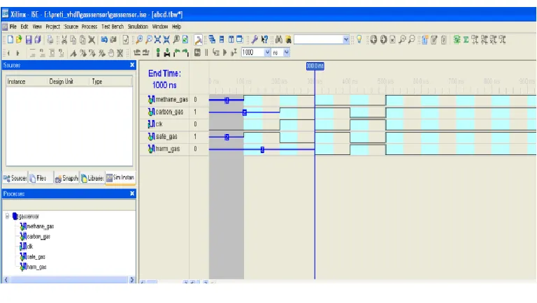
Fig-3: Test bench waveform
Fig 3 shows the test bench waveform of methane gas detection system by VHDL programming.
We took a methane _gas and clk as an input Safe_gas&harm_gaslevel is shown in output for defined concentration level of gases (ppm) in terms of decimal to BCD conversion form.
[image:6.612.175.434.96.264.2] [image:6.612.114.498.342.559.2]© 2015, IRJET ISO 9001:2008 Certified Journal Page 2570 Fig-4: Proposed Model of Gas Sensor
Fig4 Shows that the proposed model for gas detection system in which concentration of gases in terms of ppm as a input and then decimal to BCD conversion and after that FPGA Implementation will be done with LCD Interfacing.
8. Conclusion
In this paper , we described MOS based gas sensor by using xilinx software in which VHDL programming is done
.Various concentration of gases is to be taken like carbon di oxide(CO
2),methane(CH
4) and carbon-mono-oxide
(CO).
References
[1] Contreras, J.; Costa, D.; Pereira, S.; Fortunato, E.; Martins, R.; Wierzbicki, R.; Heerlein, H.; Ferreira, I. Micro Cantilever Movement Detection with an Amorphous Silicon Array of Position Sensitive Detectors. Sensors2010, 10, 8173–8184.
[2] Germano, J.; Martins, V.C.; Cardoso, F.A.; Almeida, T.M.; Sousa, L.; Freitas, P.P.; Piedade, M.S. A Portable and Autonomous Magnetic Detection Platform for Biosensing.Sensors2009, 9, 4119–4137.
[3]Gibson, D.; MacGregor, C.A Novel Solid State Non-Dispersive Infrared CO2 Gas Sensor Compatible with Wireless and Portable Deployment.Sensors2013, 13, 7079–7103.
[4] Wilmshurst, T.H. Signal Recovery from Noise in Electronic Instrumentation, 2nd ed.; Taylor&Francis Group: New York, NY, USA, 1990.
[5] Azzolini, C.; Magnanini, A.; Tonelli, M.; Chiorboli, G.; Morandi, C. Integrated Lock-In Amplifier for Contactless Interface to Magnetically Stimulated Mechanical Resonators. In Proceedings of the IEEE Conference on Design & Technology of Integrated Systems in Nanoscale Era, Tozeur, Tunisia, 25–27 March 2008; pp. 1–6.
[6]FayçalBenrekia 1,2,*, MokhtarAttari 1 and MounirBouhedda 2 ,Gas Sensors Characterization and Multilayer Perceptron (MLP) Hardware Implementation for Gas Identification Using a Field Programmable Gate Array (FPGA),
Received: 7 January 2013; in revised form: 31 January 2013 / Accepted: 21 February 2013 / Published: 1 March 2013
[7]Xiao Liu 1, Sitian Cheng 1, Hong Liu 1, Sha Hu 1, Daqiang Zhang 2 and HuanshengNing 1,*A Survey on Gas Sensing TechnologyReceived: 16 April 2012; in revised form: 18 June 2012 / Accepted: 13 July 2012 /
![Table 1: Comparison of Gas sensing Technologies [7]](https://thumb-us.123doks.com/thumbv2/123dok_us/8207023.817147/4.612.217.396.558.685/table-comparison-gas-sensing-technologies.webp)