585-300-602
Comcode 108356130
Issue 1
company’s behalf. Note that there may be a risk of toll fraud associated with your telecommunications system and, if toll fraud occurs, it can result in substantial additional charges for your telecommunications services.
You and your system manager are responsible for the security of your system, such as programming and configuring your equipment to pre-vent unauthorized use. The system manager is also responsible for reading all installation, instruction, and system administration docu-ments provided with this product in order to fully understand the fea-tures that can introduce risk of toll fraud and the steps that can be taken to reduce that risk. Lucent Technologies does not warrant that this product is immune from or will prevent unauthorized use of com-mon-carrier telecommunication services or facilities accessed through or connected to it. Lucent Technologies will not be responsible for any charges that result from such unauthorized use.
Lucent Technologies Fraud Intervention
If you suspect you are being victimized by toll fraud and you need technical support or assistance, call the appropriate BCS National Cus-tomer Care Center telephone number. Users of the MERLIN®, PART-NER®, and System 25 products should call 1 800 628 2888. Users of the System 75, System 85, DEFINITY® Generic 1, 2 and 3, and DEFINITY® ECS products should call 1 800 643 2353. Customers outside the continental United States should contact their local Lucent representative, or call one of the above numbers in the following man-ner:
• Dial the International Access Code; for example, 011. • Dial the country code for the U.S., that is, 01.
• Lastly, dial either of the telephone numbers provided above.
Lucent Technologies Web Page
The world wide web home page for Lucent Technologies is: http://www.lucent.com
Federal Communications Commission Statement
Part 15: Class A Statement. This equipment has been tested and found to comply with the limits for a Class A digital device, pursuant to Part 15 of the FCC Rules. These limits are designed to provide rea-sonable protection against harmful interference when the equipment is operated in a commercial environment. This equipment generates, uses, and can radiate radio-frequency energy and, if not installed and used in accordance with the instructions, may cause harmful
interfer-Ordering Information
Call: Lucent Technologies BCS Publications Center
Voice 1 800 457-1235 International Voice 317 322-6791 Fax 1 800 457-1764 International Fax 317 322-6699 Write: Lucent Technologies BCS Publications Center
2855 N. Franklin Road Indianapolis, IN 46219 Order: Document No. 585-300-602
Comcode 108356130 Issue 1, May 1999
For additional documents, refer to the section in “About This Docu-ment” entitled “Related Resources.”
You can be placed on a standing order list for this and other documents you may need. For more information on standing orders, or to be put on a list to receive future issues of this document, contact the Lucent Tech-nologies Publications Center.
Obtaining Products
To learn more about Lucent Technologies products and to order prod-ucts, contact Lucent Direct, the direct-market organization of Lucent Technologies Business Communications Systems. Access their web site at www.lucentdirect.com. Or call the following numbers: custom-ers 1 800 451 2100, account executives 1 888 778 1880 (voice) or 1 888 778 1881 (fax).
Warranty
Lucent Technologies provides a limited warranty on this product. Refer to the “Limited Use Software License Agreement” card provided with your package.
European Union Declaration of Conformity
The “CE” mark affixed to the equipment means that it conforms to the following directives. Lucent Technologies Business Communications Systems declares that DEFINITY AUDIX System equipment specified in this document conforms to the referenced European Union (EU) Directives and Harmonized Standards listed below:
EMC Directive 89/336/EEC Low-Voltage Directive73/23/EEC
■ Intended Audience v
■ Prerequisite Skills or Knowledge vi
■ How This Document Is Organized vi
■ How to Use this Document vii
■ Trademarks and Service Marks vii
■ Related Resources viii
■ How to Make Comments About This Document viii
1
Overview 1-1■ DEFINITY AUDIX System Requirements 1-1
■ Compatible Switches and Software 1-3
■ DEFINITY AUDIX Planning 1-5
2
New System Ordered with New Switch 2-13
New System Ordered for Existing Switch 3-1A
Switch Carrier Configuration Worksheets A-1■ Worksheet A-1 : Port Slot Assignments
(Before Carrier Rearrangement)A-3
■ Worksheet A-2 : Port Slot Assignments
(For Carrier Rearrangement)A-4
■ Worksheet A-3 : Port Slot Locations for
the DEFINITY AUDIX System AssemblyA-5
B
Switch Administration Worksheets B-1■ Worksheet B-1 : Administer the Voice Ports as Stations B-2 ■ Worksheet B-2 : Assign the Hunt Group B-4 ■ Worksheet B-3 : Assign the Call Coverage Path for Voice Ports B-7 ■ Worksheet B-4 : Assign the Call Coverage Path for Subscribers B-8 ■ Worksheet B-4 Digital Networking Worksheets B-9 ■ Worksheet B-16 : Administer Digital Networking Port B-10 ■ Worksheet B-17 : Administer a 7400A
Data Module and ADU —DCP Mode 2B-11
■ Worksheet B-18 : Administer a 7400A
■ Worksheet C-4 C-6 ■ Worksheet C-5 : Set System Parameters Limits C-7
■ Worksheet C-6 : Assign the Time Zone C-8
■ Worksheet C-7 : Activate Parameters and Basic Features C-9
■ Worksheet C-8 : Add Subscribers C-11
■ Worksheet C-9 : Set Up Alarm Origination C-14
D
Optional Features Worksheets D-1■ Worksheet D-1 : Administering AMIS
Analog Networking and Message DeliveryD-2
■ Worksheet D-2 : Automated Attendant D-6
■ Worksheet D-3 : Administering a Bulletin Board D-8 ■ Worksheet D-4 : Administering Outcalling D-9 ■ Worksheet D-5 : Administering Switch Recorded Announcement D-10
E
Terminal Configuration E-1■ Worksheet E-1 : Terminals E-2
F
Upgrades and Ongoing Maintenance and Administration F-1G
AUDIX System Administrator Qualifications and Duties G-1H
Request for Design Support H-1AB
Abbreviations AB-1GL
Glossary GL-1This document is designed as a supplement to the AUDIX® System Streamlined
Implementation process flow. It includes:
■ Checklists for use by the branch office when planning and implementing a
new DEFINITY® AUDIX® system sale and installation
■ Worksheets to be completed by the customer organization, the account
executive, and/or the software specialist before the DEFINITY AUDIX system is installed
NOTE:
The term
system
is used to meanDEFINITY AUDIX system
in the text, the chapter titles, and the table titles throughout this document.Intended Audience
This document is designed for the following audiences:
■ Account Executive — Pre-sale
■ Customer Support Representative — Post-sale and pre-next-sale ■ Project Manager — Pre-sale and post-sale
Implementation Support Center (MMISC), the National Service Assistance Center (NSAC), International Technical Assistance Center (ITAC), the Centers of Excellence (COEs), and the Sales & Design Support Center (SDSC)1 — Pre- and post-sale
Prerequisite Skills or Knowledge
This document is written with the assumption that readers are familiar with the material in
DEFINITY AUDIX System — System Description
, 585-300-214 andDEFINITY AUDIX System — Feature Descriptions
, 585-300-206.How This Document Is Organized
Planning for the DEFINITY AUDIX System Release 4.0,
585-300-602,
covers the following topics:■ Chapter 1 describes the DEFINITY AUDIX system and general
considerations for its implementation.
■ Chapter 2 lists the tasks to be completed when the customer orders a new
DEFINITY AUDIX system with a new switch.
■ Chapter 3 lists the tasks to be completed when the customer orders a new
DEFINITY AUDIX system for a switch that is already installed at the customer site.
■ Appendix A provides worksheets for the account executive, software
specialist, or design specialist to complete if the DEFINITY AUDIX system is to be installed into a switch that is already at the customer site. The worksheets can also be used if the DEFINITY AUDIX system is to be moved to different slots in the switch in which it currently resides or to a new switch.
■ Appendix B provides worksheets for the software specialist or the design
specialist to complete with the customer before initial switch administration.
■ Appendix C provides worksheets for the customer to complete before
initial DEFINITY AUDIX administration.
■ Appendix D provides worksheets for the customer to complete before
■ Appendix G provides an overview of system administration tasks and
recommended qualifications for the system administrator.
■ Appendix Hprovides a worksheet for design support. ■ List of Abbreviations.
■ Glossary. ■ Index.
How to Use this Document
To use this document, follow the implementation process flow as outlined in the appropriate implementation chapter — either Chapter 2 or Chapter 3. The tasks indicate at which points in the process flow the worksheets in the appendixes of this book should be completed. Where it is appropriate, the directions for a task refer the reader to a specific DEFINITY AUDIX system or switch document for further information.
Implementation tasks may vary for certain modes of operation for the system, such as control link integration and analog port emulation. This document does not include any information about these procedures. For information about special considerations for control link integration and analog port emulation, see
DEFINITY AUDIX System — System Description
, 585-300-214 or Installation and
Switch Administration for the DEFINITY AUDIX System Release 4.0,
585-300-122.Trademarks and Service Marks
The following trademarked products are mentioned in this document:
recommended for use in conjunction with this document:
■
DEFINITY AUDIX System — System Description
, 585-300-214, andDEFINITY AUDIX System — Feature Descriptions
, 585-300-206, describe the DEFINITY AUDIX system hardware and features not covered in this document.■ I
nstallation and Switch Administration for the DEFINITY AUDIX System
Release 4.0,
585-300-122,contains detailed installation and migration instructions, as well as instructions for administering the DEFINITY AUDIX system and its switch.■
DEFINITY AUDIX System Release 4.0 — Maintenance
, 585-300-121,DEFINITY AUDIX System — Administration
, 585-300-507, andDEFINITY
AUDIX System Release 4.0 — Screens Reference
, 585-300-213, provide information about ongoing maintenance and ongoing administration.How to Make Comments About This
Document
While we have tried to make this document fit your needs, we are interested in your suggestions for improving it. We encourage your comments or suggestions to:
Lucent Technologies Product Documentation Room 22-2X57
11900 North Pecos Street Denver, CO 80234
1
This document is designed to help make a DEFINITY AUDIX system installation run as smoothly as possible. It is to be used in conjunction with documents for the AUDIX Streamlined Implementation process and other DEFINITY AUDIX documents.
DEFINITY AUDIX System
Requirements
A prospective purchaser of the DEFINITY AUDIX system should be aware of the following system requirements:
■ The DEFINITY AUDIX system can be installed in a System 75 R1V3, a
System 75 XE, a DEFINTY Generic 1, a DEFINITY Generic 3, or a DEFINITY Generic 3csi (ProLogix). See Table 1-1 for a list of compatible switches and switch software loads.
■ Lucent Technologies only supports configurations with one DEFINITY
AUDIX system per switch.
■ The DEFINITY AUDIX system requires two1 contiguous universal port
slots.
For details on the carriers and universal port slots into which a DEFINITY AUDIX system can be installed, see Appendix A.
■ With the maximum configuration, a customer can administer up to 2000
AUDIX system can also emulate a TN2181, 16-port digital circuit pack.3 When the switch recognizes the DEFINTY AUDIX system as a TN754 or a TN2181 digital port circuit pack, it is operating in
non-native mode
. For more information about native and non-native mode, seeDEFINITY AUDIX
System — System Description
, 585-300-214.NOTE:
Even though the DEFINITY AUDIX system should emulate a TN2181 digital port circuit pack in switch releases G3V2 and above,
DEFINITY AUDIX system Release 4.0 supports a maximum of 12 voice ports without Digital Networking or 8 voice ports with Digital Networking.
NOTE:
This document only covers display set integration. Under certain conditions, some customers may be able to operate the DEFINITY AUDIX system in control link integration. In these cases, other board emulation types may apply. See
DEFINITY AUDIX System Release
4.0 — System Description
, 585-300-214, for more information about switch integration and port board emulation types.■ The DEFINITY AUDIX system provides Multilingual capability. The system
can carry up to nine Multilingual announcement sets. A special
Telecommunications Device for the Deaf (TDD) announcement set is also available.
■ The DEFINITY AUDIX system supports one Digital Networking channel.
NOTE:
For low-speed, DCP Mode 2 Digital Networking connections, the system supports a maximum of 100 local subscribers and 10,000 remote subscribers.
■ The DEFINITY AUDIX system supports AMIS Analog Networking. ■ The DEFINITY AUDIX system can be the AUDIX server on a local area
network (LAN) for subscribers using INTUITY Message Manager on their PCs. Up to 500 INTUITY Message Manager subscribers can have a
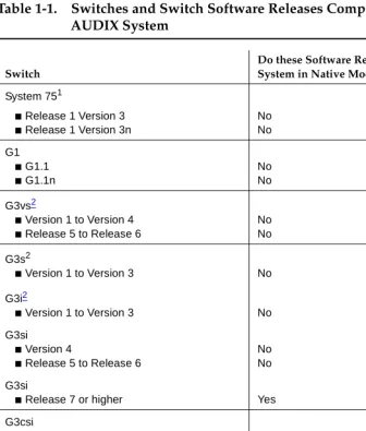
Compatible Switches and Software
The DEFINITY AUDIX system can be installed in the following switches:
■ System 75 R1V3, System 75 R1V3n ■ System 75 XE
■ DEFINITY Communications System Generic 1 ■ DEFINITY Communications System Generic 3i ■ DEFINITY Communications System Generic 3s ■ DEFINITY Communications System Generic 3si
■ DEFINITY Communication System Generic 3csi (ProLogix) ■ DEFINITY Communications System Generic 3vs
AUDIX System
Switch
Do these Software Releases Support the System in Native Mode?
System 751
■ Release 1 Version 3
■ Release 1 Version 3n
1. MFATs cannot be used to access the DEFINITY AUDIX system with DEFINITY switch Release 5.3. Use of MFATs with the DEFINITY AUDIX system is supported in all software releases above 5.3.
No No
G1
■ G1.1
■ G1.1n
No No
G3vs2
■ Version 1 to Version 4
■ Release 5 to Release 6
No No
G3s2
■ Version 1 to Version 3
2. The Transfer Out of AUDIX feature is not supported on these switches prior to G3V2g.04.5.0.099.
No
G3i2
■ Version 1 to Version 3 No
G3si
■ Version 4
■ Release 5 to Release 6
No No
G3si
■ Release 7 or higher Yes
G3csi
■ Release 6 No
G3csi
■ Release 7 or higher Yes
G3r
■ Version 1 to Version 4
■ Release 53 to Release 6
3. These switch releases do not support the use of multifunction analog telephones (MFATs) with the DEFINITY AUDIX system. The DEFINITY G3r switch supports MFATs in all releases above 5.3.
No No
G3r
DEFINITY AUDIX Planning
In planning and implementing a DEFINITY AUDIX installation, the customer and Lucent Technologies employees must coordinate their efforts for the needs assessment/contract, pre-installation, installation, and post-installation activities. The following chapters contain an overview of the tasks that must be performed during each of these phases.
Throughout the implementation process, the Lucent Technologies project manager should be the customer’s single point of contact. If the customer needs assistance with the DEFINITY AUDIX system after the cutover is complete and the system is accepted, the customer should contact the appropriate service organization:
■ Customers in the U.S. should contact the TSC at 1-800-242-2121. ■ Customers outside the U.S. should contact their COEs.
Switch Type
Maximum Number of Voice Ports with Digital Networking
Maximum Number of Voice Ports without Digital Networking
2
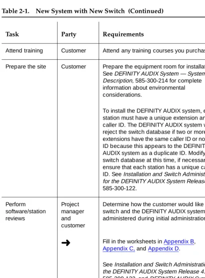
Table 2-1 is a checklist that summarizes the tasks required for planning and installing the DEFINITY AUDIX system when it is ordered with a new switch. The checklist is designed to help all parties involved coordinate their planning and implementation activities. Where it is appropriate, tasks refer to documents that contain more detailed instructions or information.
The symbol
➜
in the checklist points to a worksheet in the appendixes that should be filled in at that point in the planning process.Table 2-1 is designed to be used in conjunction with the AUDIX Streamlined Implementation process flow. For more detailed information on DEFINITY AUDIX implementation, see the binders produced for AUDIX Streamlined
Implementation. These binders should be in each Lucent Technologies branch office.
Performing Assessment and Contract Tasks Complete needs assessment Account executive
Determine the appropriate voice messaging and software application solution for the customer. If a DEFINITY AUDIX system is the best solution, determine the approximate number of voice ports, hours of voice storage, and PC software applications the customer needs. For further information about DEFINITY AUDIX capacity and sizing, see DEFINITY AUDIX System — System Description, 585-300-214.
If the DEFINITY AUDIX system will be used as a server for INTUITY Message Manager over a local area network (LAN), work with the customer’s LAN administrator to set up a demarcation point on the wallfield. This point must be within 25 feet from the back of the switch. A 10BaseT connection is needed. Lucent Technologies provides a 104A mounting block as the demarcation point on the wall for this connection to plug into. Lucent Technologies also provides a D8W modular wall cord to make the connection between the mounting block and DEFINITY AUDIX adapter cable.
➜
Fill in Worksheet C-2 to identify the equipment needed for INTUITY Message Manager.➜
Determine whether the customer will use AMIS Analog or Digital Networking. Fill outWorksheet D-1. For more information about the system’s requirements for AMIS Analog and Digital Networking, see DEFINITY AUDIX System Release 4.0 — System Description, 585-300-214.
➜
Fill in Worksheet C-1 and Worksheet C-7 to activate the Multilingual option and Worksheet C-8 to specify language sets.Identify any peripheral equipment the customer needs, including terminals, modems, and cables not included with the DEFINITY AUDIX system PEC.
➜
Fill in Worksheet E-1.Generate a configuration Account executive or design specialist
See DEFINITY AUDIX System — System Description, 585-300-214 for detailed information about the DEFINITY AUDIX system.
➜
If the customer wants to use DigitalNetworking, complete form 1154 in Appendix H. Review equipment room requirements Project manager or account executive
See DEFINITY AUDIX System — System Description, 585-300-214 for detailed information about environmental considerations.
Review the equipment room’s environmental requirements with the customer and obtain the customer's signature.
Preparing for Installation
Order
documentation
Account executive
The CD-ROM, DEFINITY AUDIX System Release 4.0 Documents, 585-300-803, includes the following documentation:
Planning for the DEFINITY AUDIX System Release 4.0, 585-300-602
DEFINITY AUDIX System — System Description, 585-300-214
DEFINITY AUDIX System — Feature Descriptions, 585-300-206
BCS Product Security Handbook, 555-025-600
DEFINITY AUDIX System — Administration, 585-300-507
DEFINITY AUDIX System Release 4.0 — Screens Reference, 585-300-213
Installation and Switch Administration for the DEFINITY AUDIX System Release 4.0, 585-300-122
DEFINITY AUDIX System Release 4.0 — Maintenance, 585-300-121
AUDIX Administration and Data Acquisition Package, 585-302-502
AMIS Analog Networking, 585-300-512
DEFINITY AUDIX System — Digital Networking, 585-300-534
Order training Account Executive
Attend training Customer Attend any training courses you purchased.
Prepare the site Customer Prepare the equipment room for installation. See DEFINITY AUDIX System — System Description, 585-300-214 for complete information about environmental considerations.
To install the DEFINITY AUDIX system, each station must have a unique extension and caller ID. The DEFINITY AUDIX system will reject the switch database if two or more extensions have the same caller ID or no caller ID because this appears to the DEFINITY AUDIX system as a duplicate ID. Modify the switch database at this time, if necessary, to ensure that each station has a unique caller ID. See Installation and Switch Administration for the DEFINITY AUDIX System Release 4.0, 585-300-122. Perform software/station reviews Project manager and customer
Determine how the customer would like the switch and the DEFINITY AUDIX system administered during initial administration.
➜
Fill in the worksheets in Appendix B, Appendix C, and Appendix D.See Installation and Switch Administration for the DEFINITY AUDIX System Release 4.0, 585-300-122, and DEFINITY AUDIX System — Administration, 585-300-507, for information about translations and administration.
Discuss the system password with the customer. Customers can change the system password for the cust login to whatever they want. Lucent Technologies controls the password for the craft and other logins, so the RSC can perform remote maintenance
Allocate a Direct Inward Dialing (DID) or Central Office (CO) Line for the AUDIX maintenance port
Project manager and customer
The customer is responsible for providing a remote-maintenance access line to the modem of the DEFINITY AUDIX system. The customer can purchase a 1FB from the local telephone service provider or provide a DID line from the switch. A circuit terminating at the switch console or other answering position is not suitable.
Check the customer site
Project manager
Verify that the customer’s equipment room is ready for equipment delivery.
Receive equipment
Customer Receive the switch with the DEFINITY AUDIX system installed.
Installing the System
Install the DEFINITY AUDIX hardware
Installer Install the cables, modems, terminals, and any other peripheral equipment as described in Installation and Switch Administration for the DEFINITY AUDIX System Release 4.0, 585-300-122.
Test the hardware Installer Test the DEFINITY AUDIX hardware. See Installation and Switch Administration for the DEFINITY AUDIX System Release 4.0, 585-300-122, for detailed instructions.
Perform initial switch administration Software specialist or design specialist
Use the worksheets from Appendix B and the instructions in Installation and Switch
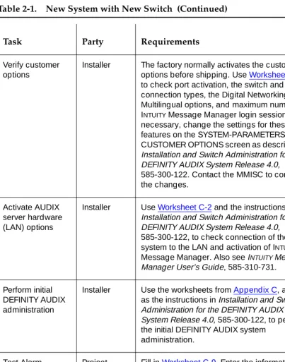
Verify customer options
Installer The factory normally activates the customer options before shipping. Use Worksheet C-1 to check port activation, the switch and port connection types, the Digital Networking and Multilingual options, and maximum number of INTUITY Message Manager login sessions. If necessary, change the settings for these features on the SYSTEM-PARAMETERS CUSTOMER OPTIONS screen as described in Installation and Switch Administration for the DEFINITY AUDIX System Release 4.0, 585-300-122. Contact the MMISC to confirm the changes.
Activate AUDIX server hardware (LAN) options
Installer Use Worksheet C-2 and the instructions in Installation and Switch Administration for the DEFINITY AUDIX System Release 4.0, 585-300-122, to check connection of the system to the LAN and activation of INTUITY
Message Manager. Also see INTUITY Message Manager User’s Guide, 585-310-731.
Perform initial DEFINITY AUDIX administration
Installer Use the worksheets from Appendix C, as well as the instructions in Installation and Switch Administration for the DEFINITY AUDIX System Release 4.0, 585-300-122, to perform the initial DEFINITY AUDIX system
administration. Test Alarm Origination Project manager
➜
Fill in Worksheet C-9. Enter the information from this worksheet on the
SYSTEM-PARAMETERS MAINTENANCE screen and then test the Alarm Origination feature.
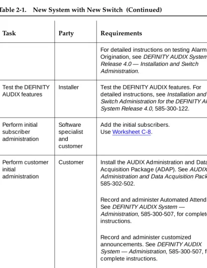
For detailed instructions on testing Alarm Origination, see DEFINITY AUDIX System Release 4.0 — Installation and Switch Administration.
Test the DEFINITY AUDIX features
Installer Test the DEFINITY AUDIX features. For detailed instructions, see Installation and Switch Administration for the DEFINITY AUDIX System Release 4.0, 585-300-122.
Perform initial subscriber administration Software specialist and customer
Add the initial subscribers. Use Worksheet C-8.
Perform customer initial
administration
Customer Install the AUDIX Administration and Data Acquisition Package (ADAP). See AUDIX Administration and Data Acquisition Package, 585-302-502.
Record and administer Automated Attendants. See DEFINITY AUDIX System —
Administration, 585-300-507, for complete instructions.
Record and administer customized announcements. See DEFINITY AUDIX System — Administration, 585-300-507, for complete instructions.
Identify primary and secondary language announcement sets. See DEFINITY AUDIX System — Administration, 585-300-507, for complete instructions.
Test any features you administered in this step.
Back up the data you entered using the magneto-optical disk drive.
Administer Digital Networking per spec provided
Software specialist
Administer and test Digital Networking. See Appendix B for more information about Digital Networking.
3
Table 3-1 is a checklist that summarizes the tasks required for planning and installing a DEFINITY AUDIX system when it is ordered for a switch that the customer already has on site. The checklist is designed to help all parties involved coordinate their planning and implementation activities. Where it is appropriate, tasks refer to documents that contain more detailed instructions or information.
The symbol
➜
in the checklist points to a worksheet in the appendixes that should be filled in at that point of the planning process.Table 3-1 is designed to be used in conjunction with the AUDIX Streamlined Implementation process flow. For more detailed information on DEFINITY AUDIX implementation, see the binders produced for AUDIX Streamlined
Implementation. These binders should be in each Lucent Technologies branch office.
NOTE:
This table does not include information about control link integration, which may be relevant for some DEFINITY AUDIX system
Performing Assessment and Contract Tasks
Complete needs assessment
Account executive
Determine the appropriate voice messaging and software application solution for the customer. If a DEFINITY AUDIX System is the best solution, determine the
approximate number of voice ports, hours of voice storage, and PC software applications the customer needs. For further information about DEFINITY AUDIX capacity and sizing, see DEFINITY AUDIX System — System Description, 585-300-214.
Verify that the switch and switch software load can accommodate the DEFINITY AUDIX System. See Table 1-1 for a list of compatible switches and switch software loads.
➜
Determine whether the customer will operate the system in display set or control link integration. Fill in Worksheet A-1 to identify the equipment needed for the connection. See Installation and Switch Administration for the DEFINITY AUDIX System Release 4.0, 585-300-122, for detailed information about control link integration.NOTE:
If the DEFINITY AUDIX system will be used as a server for INTUITY Message Manager over a LAN, work with the customer’s LAN administrator to set up a demarcation point on the wallfield. This point must be within 25 feet from the back of the switch. A 10BaseT connection is needed. Lucent Technologies provides a 104A mounting block as the demarcation point on the wall for this connection to plug into. Lucent
Technologies also provides a D8W modular wall cord to make the connection between the mounting block and the DEFINITY AUDIX adapter cable.
➜
Fill in Worksheet C-2 to identify the equipment needed for INTUITY Message Manager.➜
Determine whether the customer will use AMIS Analog or Digital Networking. Fill out Worksheet D-1. For more information about the system’s requirements for AMIS Analog and Digital Networking, see DEFINITY AUDIX System Release 4.0 — System Description, 585-300-214.Determine what primary and secondary Multilingual announcement sets will be used.
➜
Fill in Worksheet C-1 and Worksheet C-7 to activate the Multilingual option, and Worksheet C-8 to specify language sets.Identify any peripheral equipment needed, including terminals, modems, and cables not included with the DEFINITY AUDIX system PEC.
Determine DEFINITY AUDIX location
Account executive
See DEFINITY AUDIX System — System Description, 585-300-214 for detailed information about environmental considerations.
Complete the Switch Carrier Configuration worksheets in Appendix A, and find two contiguous port slots (one slot in a CMC) into which the DEFINITY AUDIX system can be installed. Give the completed worksheets to the project manager.
Generate a configuration
Account executive
See DEFINITY AUDIX System — System Description, 585-300-214, for detailed information about the DEFINITY AUDIX system.
➜
If the customer wants to use Digital Networking, complete form 1154 in Appendix H.Perform site survey Project manager
Verify that the switch and switch software load can accommodate the DEFINITY AUDIX system. See Table 1-1 for a list of compatible switches and switch software loads.
Using the information in Appendix A, make sure there are enough contiguous slots available in a carrier that are suitable for the DEFINITY AUDIX system.
Review equipment room requirements Project manager or account executive
Preparing for Installation
Order documentation Account executive
If the customer wants documentation to arrive before the DEFINITY AUDIX system, order it at this time, or any time before you place the order for the system.
The CD-ROM, DEFINITY AUDIX System Release 4.0 Documents, 585-300-803, includes the following documentation:
Planning for the DEFINITY AUDIX System Release 4.0, 585-300-602
DEFINITY AUDIX System — System Description, 585-300-214
DEFINITY AUDIX System — Feature Descriptions, 585-300-206
BCS Product Security Handbook, 555-025-600
DEFINITY AUDIX System — Administration, 585-300-507
DEFINITY AUDIX System Release 4.0 — Screens Reference, 585-300-213
Installation and Switch Administration for the DEFINITY AUDIX System Release 4.0, 585-300-122
DEFINITY AUDIX System Release 4.0 — Maintenance, 585-300-121
AUDIX Administration and Data Acquisition Package, 585-302-502
DEFINITY AUDIX System — Digital Networking, 585-300-534
Attend training Customer If you purchased any DEFINITY AUDIX system training classes, attend before the system arrives. If you want to purchase the CD-ROM-based training courses for administration, order it before the system arrives.
Order switch carrier reconfiguration
Project manager
Place an order for switch carrier reconfiguration, if required. Any switch carrier reconfiguration should be completed before material on job (MOJ) for the DEFINITY AUDIX hardware.
Perform software and station reviews
Project manager and customer
Determine how the customer wants the switch and the DEFINITY AUDIX system administered during initial administration.
➜
Fill in the worksheets in Appendix B, Appendix C, and Appendix D.SeeInstallation and Switch Administration for the DEFINITY AUDIX System Release 4.0, 585-300-122, and DEFINITY AUDIX System — Administration, 585-300-507, for
complete information on translations and administration.
Discuss the system password with the customer. Customers can change the system password for the cust login to whatever they want. Lucent Technologies controls the password for the craft and other logins, so the RSC can perform remote maintenance.
Remove switch translations
Installer Remove any translations for circuit packs to be moved to reconfigure the carrier. For detailed information on using switch administration screens, see the
implementation manual appropriate for the customer’s switch.
Reconfigure switch carrier
Installer See Worksheet A-1 and Worksheet A-2 to see which circuit packs should be moved. Perform remove and add functions to move the circuit packs. Rewire cables and cross-connect field, as required. See the customer’s switch documentation for information on using switch screens.
Administer moved circuit packs
Installer Administer any circuit packs that were moved. Test the switch for the new physical arrangement of the circuit packs and for proper administration.
Check the customer site
Project manager
If reconfiguration was required for the carrier circuit pack, verify the reconfiguration is complete.
Allocate a Direct Inward Dialing (DID) or Central Office (CO) Line for AUDIX maintenance port
Project manager and customer
Prepare the site Customer Prepare equipment room for installation. See DEFINITY AUDIX System — System Description, 585-300-214, for complete information about environmental considerations.
In order to install the DEFINITY AUDIX system, each station needs a unique extension and caller ID. For example, the DEFINITY AUDIX system will reject the switch database if two extensions have the same caller ID. The DEFINITY AUDIX system will also reject the database if there is more than one extension with no caller ID because this appears to the system as a duplicate ID. Modify the switch database at this time, if necessary, to ensure that each station has a unique caller ID.
Receive equipment Customer Receive the DEFINITY AUDIX system.
Installing the System
Install the DEFINITY AUDIX Hardware
Installer Install the DEFINITY AUDIX hardware in the slots designated on Worksheet A-2.
Install cables, terminals, modems, and any other peripherals. See Installation and Switch Administration for the DEFINITY AUDIX System Release 4.0, 585-300-122, for detailed instructions.
Test the hardware Installer Test the DEFINITY AUDIX hardware. See Installation and Switch Administration for the DEFINITY AUDIX System Release 4.0, 585-300-122, for detailed instructions.
Perform initial switch administration
Software specialist or design specialist
Verify customer options
Installer The factory normally activates the customer options before shipping. Use Worksheet C-1 to check port activation, the switch and port connection types, the Digital Networking and Multilingual options, and maximum number of INTUITY Message Manager login sessions. If necessary, change the settings for these features on the
SYSTEM-PARAMETERS CUSTOMER OPTIONS screen as described in
Installation and Switch Administration for the DEFINITY AUDIX System Release 4.0, 585-300-122. Then contact the MMISC to confirm the changes.
Activate AUDIX server hardware (LAN) options.
Installer Use Worksheet C-2 and the instructions in Installation and Switch Administration for the DEFINITY AUDIX System Release 4.0, 585-300-122, to check connection of the system to the LAN and activation of INTUITY
Message Manager. Also see INTUITY
Message Manager User’s Guide, 585-310-731. Perform initial DEFINITY AUDIX administration Software specialist
Use the worksheets from Appendix C, as well as the instructions in Installation and Switch Administration for the DEFINITY AUDIX System Release 4.0, 585-300-122, to perform the initial DEFINITY AUDIX system administration.
Test Alarm Origination Project Manager
➜
Fill in Worksheet C-9. Enter the information from this worksheet on the
SYSTEM-PARAMETERS MAINTENANCE screen and then test the Alarm Origination feature.
For detailed instructions on testing Alarm Origination, see DEFINITY AUDIX System Release 4.0 — Installation and Switch Administration.
Test the DEFINITY AUDIX features
Installer Test the DEFINITY AUDIX features. For detailed instructions, see Installation and Switch Administration for the DEFINITY AUDIX System Release 4.0, 585-300-122.
Perform initial subscriber administration Software specialist and customer
Add the initial subscribers. Use Worksheet C-8.
Perform customer initial administration
Customer Install the AUDIX Administration and Data Acquisition Package (ADAP). See AUDIX Administration and Data Acquisition Package, 585-302-502.
Administer and record automated
attendants. See DEFINITY AUDIX System — Administration, 585-300-507, for complete instructions.
Record and administer customized announcements. See DEFINITY AUDIX System — Administration, 585-300-507, for complete instructions.
Identify primary and secondary language announcement sets. See DEFINITY AUDIX System — Administration, 585-300-507, for complete instructions.
Test any features you administered in this step.
Back up the data you entered using the magneto-optical disk drive.
Administer Digital Networking
Installer Test and administer Digital Networking. See Appendix B for more information about Digital Networking.
A
To install a DEFINITY AUDIX system in a System 75 or DEFINITY switch at a customer site, the switch must have two1 contiguous port slots available in a carrier. If the switch does not have two contiguous port slots available, the system will have to be rearranged or a new carrier purchased.
NOTE:
Verify that the switch and switch software load can accommodate the DEFINITY AUDIX system. See Table 1-1 for a list of compatible switches and switch software loads.
Whoever is assigned the task of reconfiguring the circuit packs should complete the following steps:
1. Complete Worksheet A-1. In the first row, indicate the of carrier, such as port carrier or control carrier. In the remaining rows, write the circuit pack currently occupying the indicated port slot. The total number of port slots depends on the type of switch and function of the carrier.
2. Using the carrier configuration rules in the correct document for the customer’s switch, determine how two1 contiguous port slots can be obtained for the DEFINITY AUDIX system.
■ For System 75, R1V3, use
AT&T System 75 Reference Manual,
System Description
, 555-200-200, Issue 3 or later■ For System 75 G1, and G3V1, use
DEFINITY Communications
System Generic 1 and System 75 Feature Description,
555-200-201■ For G3V2 or higher, use
DEFINITY Communications System
Generic 3 System Description and Specifications
, 555-230-201, Issue 2 or higher.■ For ProLogix R6 or higher,
DEFINITY Enterprise Communications
Server Release 6 — System Description Pocket Reference
, 555-230-211, Issue 3 or higher.In reconfiguring the circuit packs use the following guidelines:
■ Move as few packs as possible; look for a carrier that has one or
two contiguous port slots already available.
■ Consider the costs of testing once the carrier has been rearranged
(for example, tie trunks and DS1 packs are more expensive to test than some other types of circuit packs).
■ Keep in mind the ease with which circuit packs can be moved.
Some circuit packs are listed below in order of easiest to most difficult to move. This list, however, is not complete:
— Analog packs: stations, CO, WATS, DID, and AUX — Hybrid packs
— Digital packs
NOTE:
(Try to avoid packs associated with any of the following: data sets with many feature buttons, console, data lines, emergency transfer line, CEO’s line, speech synthesizers, announcements.) — BRI packs
— Tone detector packs — Tie trunk packs — ISDN packs — DS1 packs
— Pooled modem packs
— Tone Clock Board (not movable) — ASAI-related packs
3. Complete Worksheet A-2 to show which two1 contiguous slots the
Complete the following worksheet to indicate how circuit packs are currently arranged in the switch carrier.
On the worksheet, the slots are numbered as seen from the
front
of the carrier, with slot 1 on the far left and slot 20 on the far right. It is not necessary to fill in the worksheet for all existing circuit packs. Specify only those circuit packs that must be moved (if any) in the carrier reconfiguration process.Date _________________________
Prepared by _________________________ Contact telephone number _________________________
Carrier A Carrier B Carrier C Carrier D Carrier E
Carrier Function
Port slot 1
Port slot 2
Port slot 3
Port slot 4
Port slot 5
Port slot 6
Port slot 7
Port slot 8
Port slot 9
Port slot 10
Port slot 11
Port slot 12
Port slot 13
Port slot 14
Port slot 15
Port slot 16
Port slot 17
Complete the following worksheet to indicate how circuit packs should be arranged in the switch carrier before the DEFINITY AUDIX system is installed. On the worksheet, the slots are numbered as seen from the
front
of the carrier, with slot 1 on the far left and slot 20 on the far right. It is not necessary to fill in the worksheet for all existing circuit packs. Specify only the new positions of circuit packs that must be moved (if any) and then indicate the two slots the DEFINITY AUDIX system is to occupy.Use the information in this appendix to determine the carrier into which the DEFINITY AUDIX system should be installed.
Date _________________________
Prepared by _________________________ Contact telephone number _________________________
Carrier A Carrier B Carrier C Carrier D Carrier E
In the worksheet below, specify the locations of the two (one for a CMC) contiguous slots into which the DEFINITY AUDIX system assembly is to be installed.
The two contiguous slots are administered with codes or left blank as listed in the following table. The assignments are dependent on the switch type. The
right-hand slot will connect with the TN568 circuit pack.
Date _________________________
Prepared by _________________________ Contact telephone number _________________________
Slot occupied by
DEFINITY AUDIX System
Digital Port
Equipment Location1
1. For System 75, the equipment location is a 5-character identifier; the first character identifies the carrier, the second and third characters identify the slot number, and the fourth and fifth characters identify the port number. For example, a valid location for System 75 is B0701: carrier B, slot 07, and port 01. For all other switches, an additional 1 or 2 digits is prepended to the carrier, slot, and port location to identify the cabinet. For example, the location 02B0701 specifies cabinet 02, carrier B, slot 07, port 01.
first
second
Switch Left-hand slot Right-hand slot
All switch releases 7.1 or higher
ADX12D
ADX8D
TN568
All switch release lower than 7.1
TN754
B
Before a software associate or software specialist can perform initial switch administration, he or she must obtain certain information from the customer. This appendix has worksheets that a software associate or software specialist and the customer should complete before installation. The worksheets include
information necessary for required switch administration and any optional switch features the customer wants to use. These tasks are described in detail in
I
nstallation and Switch Administration for the DEFINITY AUDIX System Release
4.0,
585-300-122.Worksheets are included for the following tasks:
■ Administer the voice ports as stations ■ Assign the hunt group
■ Assign the call coverage group for voice ports ■ Assign the call coverage path for subscribers ■ Administer digital networking ports
■ Administer 7400A data module or ADU
■ Assign a hunt group for the digital networking ports ■ Administer a modem
■ Assign the hunt group for data modules, ADUs, and modems
In this appendix, the following conventions apply for values listed in the right-hand column of the worksheets:
The information in the following tables is required for administering the DEFINITY AUDIX voice ports on the switch. For more information on these fields, see
I
nstallation and Switch Administration for the DEFINITY AUDIX System Release
4.0,
585-300-122.NOTE:
All digital ports must be administered on the switch and on the DEFINITY AUDIX system regardless of how many ports the customer purchased. However, only the number of ports actually purchased are administered in the hunt group.
Prepared by _________________________ Contact telephone number _________________________
Extension
Complete next table. See next table
Set type options, digital port emulation ADX16D (All switch releases 7.1 and higher)1 7405D (All switch releases lower than 7.1;)
Port See next table
Complete next table.
Name See next table
Complete next table.
Lock Messages n
Coverage Path
Enter the number you want to use to identify the coverage path for voice ports. This coverage path should cover all calls to the DEFINITY AUDIX hunt group.
COR
To prevent toll fraud, Lucent Technologies recommends that you select a Class of Restriction (COR) for voice ports such that subscribers can only call other numbers with the same COR. If, after careful consideration, you find that subscribers do need to be able to call numbers with different CORs, add permissions for these (one at a time) as required. (The Digital Networking, Message Delivery, and Outcalling features require that subscribers be able to access outside lines.) See DEFINITY AUDIX System — Administration, 585-300-507 for more information on preventing toll fraud.
COS
Coverage Message Retrieval [y]
Auto Answer [n]
Data Restriction [n]
Idle Appearance Preference [n]
Restrict Last Appearance
Complete next table. See next table
Coverage Module [n]
AUDIX Name (G3r only)
This name appears on the switch USER-DEFINED ADJUNCT NAMES screen.
Display Language (G3i-Global only) English
Feature Module (S75 and G1 only) [n]
Headset (S75 only) [n]
Client Room Redirection Yes
The information in the following tables is required for assigning the hunt group. Use Table B-1 for switch releases lower than G3V2 and System 75. Use Table B-2 for G3V2 and higher and Prologix.
Enter the location, name, and extension for each of the voice ports in the worksheets below.
Prepared By _________________________ Contact Telephone Number _________________________
Table B-1. G3 Lower than V2, System 75
DEFINITY AUDIX Port
Digital Port Equipment Location1
1. For System 75, the equipment location is a 5-character identifier; the first character identifies the carrier, the second and third characters identify the slot number, and the fourth and fifth characters identify the port number. As an example, a valid location for System 75 is B0701: carrier B, slot 07, and port 01. For all other switches, an additional 1 or 2 digits is prepended to the carrier, slot, and port location to identify the cabinet. For example, the location 02B0701 specifies cabinet 02, carrier B, slot 07, port 01.
Name2
2. These names are recommended. Other names are acceptable, but they must begin with AUDIX
Extension
Restrict Last Appearance
1 [AUDIX 1] n
2 [AUDIX 2] n
3 [AUDIX 3] n
4 [AUDIX 4] n
5 [AUDIX 5] n
6 [AUDIX 6] n
7 [AUDIX TRANSFER] n
The following information is required to define a hunt group (containing the voice port members) for the DEFINITY AUDIX system voice ports. Only the number of ports actually purchased should be administered in the hunt group.
1 [AUDIX 1] n
2 [AUDIX 2] n
3 [AUDIX 3] n
4 [AUDIX 4] n
5 [AUDIX 5] n
6 [AUDIX 6] n
7 [AUDIX 7] n
8 [AUDIX 8] n
9 [AUDIX 9] n
10 [AUDIX 10] n
11 [AUDIX TRANSFER] n
12 [AUDIX 12] y
Group Number
Enter the number you want to identify the DEFINITY AUDIX hunt group. (This number, preceded by an h, is entered in the voice port COVERAGE PATH screen and in subscriber coverage paths.)
Group Extension
Enter the extension number you want subscribers to dial to retrieve their messages from the DEFINITY AUDIX system.
Group Type [ucd] (DEFINITY
releases lower than 7) ucd-mia (DEFINITY releases 7.1 and higher)
Group Name
Enter the name you want to appear on display sets when subscribers call the DEFINITY AUDIX system. ("AUDIX" must be included in the name for G3-MA to recognize this name as the DEFINITY AUDIX hunt group.)
will call to reach the DEFINITY AUDIX system. For security reasons, the DEFINITY AUDIX hunt group should be assigned its own COR that is restricted from accessing all outgoing trunks or only those trunks needed for Outcalling or Digital Networking. The default COR is not recommended.
ISDN Call Disp
If ISDN-PRI is enabled, enter grp-name or mbr-name to specify whether the hunt group name or number is sent to the originating subscriber.
Queue Length
A suggested length is the number of configured DEFINITY AUDIX voice ports.
First Announcement Extension (not applicable for G3r)
If you want a switch recorded announcement, enter the extension number here.
First Announcement Delay - in seconds (not applicable for G3r)
The following information is required to define call coverage paths for the DEFINITY AUDIX voice ports.
Prepared By _________________________ Contact Telephone Number _________________________
Coverage Path Number
Use the same coverage path number as Worksheet B-1.
Coverage Criteria
Station/Group Status Active? (Inside Call/Outside Call) [n/n]
Coverage Criteria
Busy? (Inside Call/Outside Call) [n/n]
Coverage Criteria
Don’t Answer? (Inside Call/Outside Call) [n/n]
Coverage Criteria
All? (Inside Call/Outside Call) [y/y]
SAC/Go to Cover? (Inside Call/Outside Call) [n/n]
Next Path Number
If desired, enter the second path to which calls will be directed in case the current path fails.
Number of Rings use the default
Coverage Points
Point1
The following information is required to define call coverage paths for
subscribers. Complete a copy of this worksheet for each different coverage path. Prepared By _________________________ Contact Telephone Number _________________________
Coverage Path Number
Enter the number you want to identify the call coverage path for subscribers.
Coverage Criteria
Station/Group Status Active? (Inside Call/Outside Call) [n/n]
Coverage Criteria
Busy? (Inside Call/Outside Call) [y/y]
Coverage Criteria
Don’t Answer? (Inside Call/Outside Call) [y/y]
Coverage Criteria
All? (Inside Call/Outside Call) [n/n]
SAC/Go to Cover? (Inside Call/Outside Call) [y/y]
Next Path Number
If desired, enter the second path to which calls will be directed in case the current path fails.
Number of rings
Enter the number of rings (1–99) you want before a call goes to coverage. Three is recommended.
Coverage Points
NOTE:
In a DCP Mode 2 connection, the DEFINTIY AUDIX system supports a maximum of 100 local subscribers and 10,000 remote subscribers.
For more information about Digital Networking, including a complete set of Digital Networking Worksheets, see
DEFINITY AUDIX System — Digital Networking
, 585-300-534. For design support, call the SDSC.The following information is required to administer the digital networking port on a DATA MODULE screen on the switch
Prepared By _________________________ Contact Telephone Number _________________________
Assign a data extension
(Enter the data extension on the DATA MODULE screen for voice port one)
Enter a name for the data extension
Enter a name that identifies the networking port
Enter a class of restriction (COR)
Enter a class of service (COS)
The information in the following tables is required to administer a 7400A data module and ADU
For each 7400A data module or ADU used in a DCP Mode 2 modem/data module arrangement, administer a DATA MODULE screen.
Prepared By _________________________ Contact Telephone Number _________________________
Type Enter pdmfor a 7400A data module,
or enter data-linefor an ADU
Port Enter the port location of the TN754
port to which the data module connects or the TN726 port to which the ADU connects (such as 2B0701 module 2, carrier B. slot 07, port 01)
Name Enter an identifying name for the
For each 7400A data module or ADU used in a DCP Mode 2 modem/data module arrangement, administer a DATA EXTENSION screen. Complete a worksheet for each data module or ADU. The information in the following table is required to administer a 7400A data module or ADU.
Date _________________________ Prepared By _________________________ Contact Telephone Number _________________________
Type
Enter pdmfor a 7400A data module, or enter data-linefor an ADU.
Port
Enter the port location of the TN754 or TN2181 port to which the data module connects or the TN746 port to which the ADU connects (such as 2B0701, which indicates module 2, carrier B. slot 07, port 01).
Name
Enter an identifying name for the data module or ADU (such as dignet datmod1 or dignet ADU-1).
COS
COR
If Type is pdm:
Remote Loop-Around Test Secondary Data Module
[n] [n]
Connected to [dte]
ITC
Busy Out [y]
Low [n]
Speed
Enter 9.6 Kbps or 19.2 Kbps.
Autoadjust [n]
Permit Mismatch [n]
Dial Echoing [y]
Disconnect Sequence [two-breaks]
Answer Text [y]
Parity [space]
For each modem used in a DCP Mode 2 modem/data module arrangement, administer a STATION screen on the switch Complete a worksheet for each modem.
Date _________________________ Prepared By _________________________ Contact Telephone Number _________________________
Type 2500
Port
Name
Enter a name that identifies the modem (such as dignet modem1).
COS
COR
Tests [y]
LWC Reception [n]
LWC Activation [n]
Coverage Msg Retrieval [n]
CDR Privacy [n]
Auto Answer [none]
Redirect Notification [n]
Data Restriction [y]
Per Button Ring Control [n]
Call Waiting Indication [n]
Bridged Call Alerting [n]
Att. Call Waiting Indication [n]
Off Premises Station [n]
C
Before a software associate or software specialist can perform initial
administration for the DEFINITY AUDIX system, he or she needs to obtain certain information from the customer. A software associate or software specialist should have the customer complete the worksheets on the following pages before installation. The worksheets include information necessary for initial DEFINITY AUDIX system administration.
You need information from the customer before you can complete the following DEFINITY AUDIX administration tasks:
■ Activate customer options
■ Activate DEFINITY AUDIX server hardware (LAN) options ■ Assign the DEFINITY AUDIX machine ID
■ Set system parameters limits ■ Assign the time zone
■ Activate parameters and basic features ■ Add subscribers
■ Set up Alarm Origination
■ Network (completed forms should be provided with the specification)
The information you supply here will be input on the SYSTEM-PARAMETERS CUSTOMER-OPTIONS screen during installation.
Prepared By _________________________ Contact Telephone Number _________________________
Field Default Desired
Port Emulation Type TN754 or TN21811
1. For switch releases G3V2 and higher, TN2181 digital port board emulation is always preferable over TN754 emulation to accommodate system expansion.
Maximum Number of Voice Ports 2
AMIS Analog Networking n
Digital Networking2
2. For DCP Mode 2 connections, traffic restrictions may apply.
n
Maximum number of digital networking ports n
Multilingual n
The information you supply here will be input on the SYSTEM-PARAMETERS IMAPI-OPTIONS screen during installation only if the customer purchased INTUITY
Message Manager.
INTUITY Message Manager requires the following: — A 10BaseT connection to the LAN
— Transmission Control Protocol/Internet Protocol (TCP/IP) between the DEFINITY AUDIX server and the end-users’ PCs.
— IMM software
— the standard WIN socket open network programming interface Date _________________________ Prepared By _________________________ Contact Telephone Number _________________________
Field Default Desired
Maximum Number of Enabled IMAPI Sessions 32
Enable Check_new messages n y
Enable Deliver_ca_message n y
Enable Voice File Transfer n y
IMAPI Session Timeout 5
IMAPI IP Address1
1. This number is supplied by the LAN manager or administrator. The address appear in the form nnn.nnn.nnn.nnn, where each nnn can be a number between 0 and 255.
■ Release 4.3: Windows or Windows for Workgroups 3.11 or later. ■ Release 4.5: Windows 95 or Windows NT
The information you supply here will be input on the MACHINE screen during cut-to-service administration.
Enter the address ranges for subscriber extensions for each machine in the table below. The prefix can be used to distinguish between machines that have overlapping extensions.
Prepared By _________________________ Contact Telephone Number _________________________
Field Default Desired
Machine Name local
Machine Type audix audix
Location local local
Voiced Name n
Extension Length 4
Voice ID 0 0
Default Community
Messages without a community ID are assumed to have been sent from this community. See DEFINITY AUDIX System — Feature Descriptions, 585-300-206 for information on communities and the Sending Restrictions feature.
Start Extension End Extension
Machine Prefix Start Extension End Extension
1
2
3
4
5
6
and Switch Administration for the DEFINITY AUDIX System Release 4.0,
The information you supply here will be input on the SYSTEM-PARAMETERS LIMITS screen during initial administration.
Prepared By _________________________ Contact Telephone Number _________________________
Limit Default Desired
Maximum Message Length (seconds) 1200
Minimum Message Length (tenths of seconds) 10
Total Messages in all Mailboxes
The appropriate value depends on the disk size and the number of local subscribers. The recommended number is 10 times the number of subscribers.
50000
Maximum Messages Awaiting Delivery
The appropriate value depends on the disk size and the number of local subscribers. The recommended number is the number of subscribers.
5000
Maximum Number of Local Subscribers 1
1. The number of local subscribers should be 2000 or less.
The appropriate value depends on the disk size. See DEFINITY AUDIX System —
System Description, 585-300-214 for more information.
1000
Maximum Number of Administered Remote Subscribers
The appropriate value depends on the disk size. See DEFINITY AUDIX System —
System Description, 585-300-214 for more information.
1000
Total List Entries
This is the total entries allowed in all subscriber's lists. 50000
Total Number of Lists per Subscriber 100
Maximum Total Number of Recipients per List 250
The information you supply here will be input on the SWITCH TIME ZONE screen during initial administration.
Valid United States time zones are as follows:
■ Eastern — 5 ■ Central — 6 ■ Mountain — 7 ■ Pacific — 8 ■ Alaska — 9 ■ Hawaii — 10
Prepared By _________________________ Contact Telephone Number _________________________
In what time zone will your DEFINITY AUDIX system be installed (0–23)?
The information you supply here will be input on the SYSTEM-PARAMETERS FEATURES screen during cut-to-service administration.
Prepared By _________________________ Contact Telephone Number _________________________
Field Default Desired
Log-in Parameters
Maximum Login Retries 3 3
Consecutive Invalid Attempts 18
System Guest Password blank
Minimum Password Length 0
(Lucent Technologies recommends changing this field to at least 5).
Password Aging Limits (days) Subscriber Mailboxes
Password expiration interval(0 for no password aging) 0 0–999
Minimum age before changes 0 0–99
Expiration warning(0 for no warning) 0 0–99
Password Aging Limits (days) Administrator Login
Password expiration interval (0 for no password aging)
Minimum age before changes
Expiration warning(0 for no warning)
Input Time Limits (seconds)
Normal 60
Full Mailbox Timeout (seconds) 5
Wait(*W) 180
Input Time Limits (seconds)
Between digits at auto-attendant or standalone menu (3–12)
5 0
Disconnect Options
Quick Silence Disconnect? n
Silence Limit?(5–30 seconds) 30
Tone Based Disconnect? n
Miscellaneous Features
Broadcast Mailbox Extension
Traffic Collection? n
Name Record by Subscriber? y
Multiple Personal Greetings? y
End of Message Warning? y
Warning Time (seconds) 15
Priority on Call Answer? n
Call Transfer Out of AUDIX
Transfer Type? (basic/none) none
Transfer Restriction (subscribers/digits) subscribers
Covering Extension blank
Announcement Sets
System standard
Administrative blank
Rescheduling Increments For Unsuccessful Message Delivery1
1. For information on default values, see DEFINITY AUDIX System Release 4.0 —
Increment Days Hours Minutes
1
2
3
4
5
6
7
8
9
The information you supply here will be input on the SUBSCRIBER and COS screens during cut-to-service administration. Complete the following information for each subscriber to be added to the DEFINITY AUDIX database during cut-to-service administration. The minimum information needed to add a
subscriber to the DEFINITY AUDIX database is a name and an extension for the subscriber. The DEFINITY AUDIX system will supply defaults for all the remaining fields on the SUBSCRIBER screen.
You must administer the following information for each subscriber to be added to the DEFINITY AUDIX system database:
■ Subscriber name ■ Subscriber extension ■ Initial password
■ Class of Service (COS) — 12 classes of service can be defined for the
DEFINITY AUDIX system; see
DEFINITY AUDIX System
—Administration,
585-300-507 and
DEFINITY AUDIX System — System Description
, 585-300-214 for more information on Class of Service. Values for the default Class of Service, found on the CHANGE SUBSCRIBER screen (page 2) and the CHANGE COS screen, appear on the next page.■ Miscellaneous
■ Switch ID —The number identifying the switch on which the subscriber is
administered. (The default value represents the local switch.) Enter 0 if there is no station on the switch. In such a case, no lamp updates will be performed.
■ Covering extension
■ Community ID — The number identifying the community of subscribers to
which this subscriber will belong; community ID can be used to administer, for example, message sending restrictions.
Broadcast mailbox
Login Announcement Set (specific)
Call Answer Language Choice? y
Call Answer Primary Annc. Set (specific)
Call Answer Secondary Annc. Set (specific)
PERMISSIONS
Type call-answer
Announcement Control n
Outcalling n
Priority Message n
Broadcast none
IMAPI Access n
IMAPI Voice File Access n
INCOMING MAILBOX
Order fifo
Category Order nuo
New Message Retention Time 10
Old Message Retention Time 10
Unopened Message Retention Time 10
OUTGOING MAILBOX
Order fifo
Category Order ufdan
File Cabinet Retention Time 10
Delivered/Nondeliverable Retention Time 10
Voice Mail Message (seconds)
Maximum Length 300 sec.
Minimum Needed 32 sec.
Call Answer Message (Seconds)
Maximum Length 120 sec.
Minimum Needed 8 sec.
End of Message Warning Time (seconds) 15
Maximum Mailing Lists 25
Total Entries in All Lists 250
The project manager or the technician will input the information from this worksheet on the SYSTEM-PARAMETERS MAINTENANCE screen in installation Task 16. In Task 16 you will call the RSC and have them add the customer to the database and test the Alarm Origination feature.
Prepared By _________________________ Contact Telephone Number _________________________
What is the name1 of the DEFINITY AUDIX system?
1. This is a unique name the RSC uses to access the system. The RSC can help in assigning this name. Once the name is assigned, only the RSC can change it. This name is not used by any other Lucent Technologies group or by the customer.
(Lucent Technologies identifier)
What is the DEFINITY AUDIX system location?
What is the telephone number the customer can call to report problems with the DEFINITY AUDIX system or to ask for help?
In the United States this number is 1-800-242-2121.
What is the automatic alarm reporting telephone number?
This is the modem command string for automatic alarm referral calls generated by the DEFINITY AUDIX system. The INADS administrator will give this string to the installer.
Will Alarm Origination be activated through the DEFINITY AUDIX system only (enter audix only), through the switch only (enter switch only), or both (enter audix & switch).
What is the telephone number for the remote maintenance port?