75
AN AUTOMATED TOOL FOR BUSINESS RULE-DRIVEN,
OBJECT-ORIENTED SOFTWARE EVOLUTION
Wan M.N. Wan Kadir Software Engineering Department
Faculty of Compo Science and Info. Systems, Universiti Teknologi Malaysia 81310 UTM Skudai, Johor, Malaysia
e-mail: [email protected]
Abstract: In order to remain useful, it is important for software to evolve according to the changes in its business environment. The changes of highly volatile requirements, i.e. business rules, may even occur prior to system implementation. In this paper, we present an automated tool that supports the Business Rule-Driven Object-Oriented Design (BROOD) approach in propagating business rule changes to software design. We firstly introduce the BROOD approach that consists of a metamodel that defines the semantics and syntax of business rules statements and links these rules to their related software design components. The Unified Modeling Language (UML) is adopted to define the software design part of the metamodel. We also describe the design and implementation of our automated tool using Generic Modeling Environment (GME).
Keywords : Unified Modeling Language, Generic Modeling Environment, Adaptive Object
Model" metamodel, Business Rule
1. INTRODUCTION
Nowadays, nearly all of commercial and government organizations are highly dependent on software systems. Due to the inherent dynamic nature of their business environment, software evolution is inevitable. The changes generated by business policies and operations are propagated onto software system. A large portion of total software lifecycle cost is devoted to introduce new requirements, and remove or change the existing requirements [J]. However, software evolution must be accomplished for the software to remain useful in its environment [2]. Due to this reason, software evolution is considered as a key research challenge in software engineering.
Many research projects attempt to find a more applicable way for building a software system that is flexible to changes as well as predicting the effect of requirements change [3].
Jilid 20, Bil.2 (Disember 2008) Jumal TeknoJogi Maklumat
75
AN AUTOMATED TOOL FOR BUSINESS RULE-DRIVEN,
OBJECT-ORIENTED SOFTWARE EVOLUTION
Wan M.N. Wan Kadir Software Engineering Department
Faculty of Compo Science and Info. Systems, Universiti Teknologi Malaysia 81310 UTM Skudai, Johor, Malaysia
e-mail: [email protected]
Abstract:
Inorder to remain useful, it is important for software to evolve according to the changes in its business environment. The changes of highly volatile requirements, Le. business rules, may even occur prior to system implementation. In this paper, we present an automated tool that supports the Business Rule-Driven Object-Oriented Design (BROOD) approach in propagating business rule changes to software design. We firstly introduce the BROOD approach that consists of a metamodel that defines the semantics and syntax of business rules statements and links these rules to their related software design components. The Unified Modeling Language (UML) is adopted to define the software design part of the metamodel. We also describe the design and implementation of our automated tool using Generic Modeling Environment (GME).Keywords : Unified Modeling Language, Generic Modeling Environment, Adaptive Object Model" metamodel, Business Rule
1.INTRODUCTION
Nowadays, nearly all of commercial and government organizations are highly dependent on software systems. Due to the inherent dynamic nature of their business environment, software evolution is inevitable. The changes generated by business policies and operations are propagated onto software system. A large portion of total software lifecycle cost is devoted to introduce new requirements, and remove or change the existing requirements [l]. However, software evolution must be accomplished for the software to remain usefulinits environment [2]. Due to this reason, software evolution is considered as a key research challengeinsoftware engineering.
Many research projects attempt to find a more applicable way for building a software system that is flexible to changes as well as predicting the effect of requirements change [3].
• However, most of them focus more on software technology, ignoring the consideration of the
sources of changes in a software operational environment.
Business rules, which are frequently changing in accordance with the business changes [4], have been identified as the important sources of changes. In addition, their changes bring the highest impact on both software and business process [5, 6). The explicit consideration of business rules in software development is important in assisting future evolution.
In this paper, we present how the business rule approach to software evolution, which is called Business Rule-Driven Object-Oriented Design (BROOD), supports automated propagation of business rule changes to software design. It starts with a brief description of the BROOD approach. Next, it presents the design of the BROOD tool. It is followed by the demonstration of using the BROOD tool based on the examples from the web-based healthcare information system case study. Finally, we give the summary and conclusion.
2. THE BROOD ApPROACH
There are two main categories of business rule approaches to software evolution i.e. business rule conceptual modelling and evolvable software systems. Business rule conceptual modelling focus on specification issues such as the typology and structure of business rules. For example, the Business Rules Group (BRG) that classifies business rules into three main types i.e. structural assertions, action assertions, and derivations [7] and Business
Rule-Oriented Conceptual Modeling (BROCOM) that introduces a metamodel that formalizes
business rules in conceptual modelling [8, 9]. Morgan suggested formalization in terms of the pattern of business rule statements which is capable to be translated into formal logic [10]. Ross proposed the functional categories of business rules Le. rejectors, projectors, and producers [11].
With regard to evolvable software systems, business rule extemalization in software implementation was considered as the main objective. Among the leading approaches is
Adaptive Object Model (AOM), which is dermed as "a system that represents classes,
attributes, and relationships as metadata" [12, 13]. Other examples include Coordination Contract and Business Rule Beans. Coordination Contract aims to separate core business entities which are relatively stable and volatile business products which keep changing for the business to remain competitive [14]. Business Rule Beans (BRBeans), formerly known as
Jilid 20, Bil. 2 (Disember 2008) Jurnal Teknologi Maklumat
ly two models are i pectively model thl
ey can be maintail 'deleted when a bush phrase is not recom
' 0 business rules. In a
elements. As shown UML model element [17] whilst the more is discussed in [18].
Jilid 20, Bil.2 (Disembl However, most of them focus more on software technology, ignoring the consideration of the
sources of changes in a software operational environment.
Business rules, which are frequently changing in accordance with the business changes [4], have been identified as the important sources of changes. In addition, their changes bring the highest impact on both software and business process [5, 6]. The explicit consideration of business rules in software development is important in assisting future evolution.
In this paper, we present how the business rule approach to software evolution, which is called Business Rule-Driven Object-Oriented Design (BROOD), supports automated propagation of business rule changes to software design. It starts with a brief description of the BROOD approach. Next, it presents the design of the BROOD tool. It is followed by the demonstration of using the BROOD tool based on the examples from the web-based healthcare information system case study. Finally, we give the summary and conclusion.
2. THEBROODApPROACH
There are two main categories of business rule approaches to software evolution i.e. business rule conceptual modelling and evolvable software systems. Business rule conceptual modelling focus on specification issues such as the typology and structure of business rules. For example, the Business Rules Group (BRG) that classifies business rules into three main types i.e. structural assertions, action assertions, and derivations [7] and Business
Rule-Oriented Conceptual Modeling (BROCOM) that introduces a metamodel that formalizes
business rules in conceptual modelling [8, 9]. Morgan suggested formalization in terms of the pattern of business rule statements which is capable to be translated into formal logic [10]. Ross proposed the functional categories of business rules i.e. rejectors, projectors, and producers [11].
With regard to evolvable software systems, business rule extemalization in software implementation was considered as the main objective. Among the leading approaches is
Adaptive Object Model (AOM), which is dermed as "a system that represents classes,
attributes, and relationships as metadata" [12, 13]. Other examples include Coordination Contract and Business Rule Beans. Coordination Contract aims to separate core business entities which are relatively stable and volatile business products which keep changing for the business to remain competitive [14]. Business Rule Beans (BRBeans), formerly known as
Accessible Business Rules [4, 15], is a framework that provides guidelines and infrastructures for the extemalization of business rules in a distributed business application.
Business Rule-Driven Object-Oriented Design (BROOD) attempts to fill the gap between business rule conceptual modelling and evolable software systems. It consists of a metamodel that defines the structure of business rules. The ultimate aim of the BROOD metamodel is to support the linking of business rules to software design, which in tum facilitates the traceability and propagation of the rule changes to its related design components. Since business rules are often managed by business users, the metamodel should naturally define business rules from the users' perspectives. At the same time, the definition should be well structured enough to be linked to software design. There are three main goals of the business rule metamodel. First, it should have an exhaustive and mutual exclusive typology to capture all possible types of business rules. Second, it should have the structured forms of expressions for linking the business rules to software design. Third, it should include rule management elements to improve business rule traceability in business domain, which consequently simplifies business rule management. These three characteristics form the basis for the development of the business rule metamodel..
The Unified Modelling Language (UML) [16] metamodel is used to represent software design since it is widely accepted in research and industry communities. In general, the UML metamodel consists of three packages Le. Foundation, Behavioral Elements and Model Management. These packages define various useful models for the understanding and specification of the system under development. For the purpose and scope of this research, only two models are included in the study namely class diagram and statechart diagram which respectively model the static and dynamic aspects of software systems.
BROOD introduces rule phrases that link the user-oriented business rule specification to software design. Rule phrases are considered as the building blocks for the rule statements. They can be maintained independently during implementation, in other words, they are not deleted when a business rule is deleted. However, the modification and deleting of a rule phrase is not recommended since a careful effort is needed in reviewing its aggregated business rules. In addition to playing a role as the building blocks for business rule statements, rule phrases are also important in linking business rules to software design elements. As shown in the metamodel in Figure 1, each rule phrase is linked to zero or more UML model elements. The conceptual framework of the BROOD approach can be found in [17] whilst the more detailed discussion specifically on the BROOD metamodel and process is discussed in [18].
Jilid 20, Bi1.2 (Disember 2008) Jumal Teknologi Maklumat
Accessible Business Rules [4, 15], is a framework that provides guidelines and infrastructures for the extemalization of business rules in a distributed business application.
Business Rule-Driven Object-Oriented Design (BROOD) attempts to fill the gap between business rule conceptual modelling and evolable software systems.Itconsists of a metamodel that defines the structure of business rules. The ultimateaim of the BROOD metamodel is to support the linking of business rules to software design, which in tum facilitates the traceability and propagation of the rule changes to its related design components. Since business rules are often managed by business users, the metamodel should naturally define business rules from the users' perspectives. At the same time, the definition should be well structured enough to be linked to software design. There are three main goals of the business rule metamodel. First, it should have an exhaustive and mutual exclusive typology to capture all possible types of business rules. Second, it should have the structured forms of expressions for linking the business rules to software design. Third, it should include rule management elements to improve business rule traceability in business domain, which consequently simplifies business rule management. These three characteristics form the basis for the development of the business rule metamodel..
The Unified Modelling Language (UML) [16] metamodel is used to represent software design since it is widely accepted in research and industry communities. In general, the UML metamodel consists of three packages Le. Foundation, Behavioral Elemt:nts and Model Management. These packages define various useful models for the understanding and specification of the system under development. For the purpose and scope of this research, only two models are included in the study namely class diagram and statechart diagram which respectively model the static and dynamic aspects of software systems.
BROOD introduces rule phrases that link the user-oriented business rule specification to software design. Rule phrases are considered as the building blocks for the rule statements. They can be maintained independently during implementation, in other words, they are not deleted when a business rule is deleted. However, the modification and deleting of a rule phrase is not recommended since a careful effort is needed in reviewing its aggregated business rules. In addition to playing a role as the building blocks for business rule statements, rule phrases are also important in linking business rules to software design elements. As shown in the metamodel in Figure I, each rule phrase is linked to zero or more UML model elements. The conceptual framework of the BROOD approach can be found in [17] whilst the more detailed discussion specifically on the BROOD metamodel and process is discussed in [18].
3. THE DESIGN OF THE BROOD TOOL
The BROOD approach simplifies the evolution activities by providing business rule traceability in object-oriented software design which in tum facilitating business rule-driven evolution. However, the process introduces several additional activities to the traditional object-oriented software development. These additional activities include the documentation of business rules and linking them to software design. Although these activities bring great benefit in the evolution of a business rule intensive software system, but they make a software development process too complicated without an automated tool support.
The BROOD tool assists users in performing the development and evolution activities such as business rule creation and management, software design editing, and business rule change propagation. It was developed on top of the Generic Modelling Environment (GME). The Generic Modeling Environment (GME) [19, 20], which was developed by the Vanderbilt University, is a configurable toolset that supports the easy creation of a modelling environment. The created modelling environment can be subsequently used for building large scale, complex models. The powerful modelling concepts such as model hierarchy, multiple aspects, sets, references and constraints are integrated in GME. GME also contains integrated model interpreters for translating and analysing the models under construction. The configurable feature of GME provides great flexibility for methodologist especially for the frequently evolved modelling paradigm. This feature was also considered as the main reason for this research to choose GME in experimenting and demonstrating its proposed concepts.
In GME, the modelling configuration is accomplished through a metamodel that specifies the modelling paradigm (or modelling language) of the application domain. The metamodel defines the syntactic, semantic and presentation information of the domain for example, the concepts that are used to construct the models, the relationships that may exist among those concepts, the organization and view of the concepts by the modeller, and the rules governing the construction of models. The metamodel is composed using different combinations of the GME modelling concepts such as model, atom, reference, connection, and aspect. The BROOD metamodel, which is discussed in section 2, is used to generate the BROOD tool environment. Figure 1 shows the example of business rule metamodel definition using GME environment.
Jilid 20, Bil. 2 (Disernber 2008) Jumal Teknologi Maklurnat
3. THE DESIGN OF THE BROOD TOOL
The BROOD approach simplifies the evolution activities by providing business rule traceability in object-oriented software design which in turn facilitating business rule-driven evolution. However, the process introduces several additional activities to the traditional object-oriented software development. These additional activities include the documentation 1 of business rules and linking them to software design. Although these activities bring great benefit in the evolution of a business rule intensive software system, but they make a software development process too complicated without an automated tool support.
The BROOD tool assists users in performing the development and evolution activities such as business rule creation and management, software design editing, and business rule change propagation. It was developed on top of the Generic Modelling Environment (GME). The Generic Modeling Environment (GME) [19, 20], which was developed by the Vanderbilt University, is a configurable toolset that supports the easy creation of a modelling environment. The created modelling environment can be subsequently used for building large scale, complex models. The powerful modelling concepts such as model hierarchy, multiple aspects, sets, references and constraints are integrated in GME. GME also contains integrated model interpreters for translating and analysing the models under construction. The configurable feature of GME provides great flexibility for methodologist especially for the frequently evolved modelling paradigm. This feature was also considered as the main reason for this research to choose GME in experimenting and demonstrating its proposed concepts.
In GME, the modelling configuration is accomplished through a metamodel that specifies the modelling paradigm (or modelling language) of the application domain. The metamodel defines the syntactic, semantic and presentation information of the domain for example, the concepts that are used to construct the models, the relationships that may exist among those concepts, the organization and view of the concepts by the modeller, and the rules governing the construction of models. The metamodel is composed using different combinations of the GME modelling concepts such as model, atom, reference, connection, and aspect. The BROOD metamodel, which is discussed in section 2, is used to generate the BROOD tool environment. Figure 1 shows the example of business rule metamodel definition using GME environment.
Figure I. Defming business rule metamodel in GME environment
We also developed three main modules (Le. interpreters in GME terms) in order to simplify the rule phrase management, business rule composition, and business rule modification. These modules also perform the automated propagation of business rule changes to the respective software design elements, which is impractical to be performed manually. The metamodel, the graphical model editor, and the above three modules are located at the core component and user application layer in the BROOD tool architecture. The rule phrase entries, business rule specification, and software design models are considered as the stroge layer in the tool architecture. The BROOD tool architecture, which is based on GME architecture, is shown in Figure 2.
Figure 2. The BROOD tool architecture [21]
GME provides a constraint manager as a general mechanism for representing modelling rules and constraints. In GME, constraints are expressed using the MultiGraph Constraint Language (MCL), a predicate logic language based on the Object Constraint Language (OCL). The constraint manager is fully compliant with the standard OCL 1.4 specification [22]. The examples of the constraints defined for the BROOD tool and their OCL specifications are given below:
Jilid 20, Bil.2 (Disember 2008) Jurnal Teknologi Maklumat Figure I. Defming business rule metamodel in GME environment
We also developed three main modules (Le. interpreters in GME terms) in order to simplify the rule phrase management, business rule composition, and business rule modification. These modules also perform the automated propagation of business rule changes to the respective software design elements, which is impractical to be performed manually. The metamodel, the graphical model editor, and the above three modules are located at the core component and user application layer in the BROOD tool architecture. The rule phrase entries, business rule specification, and software design models are consideredas the stroge layer in the tool architecture. The BROOD tool architecture, which is based on GME architecture, is shown in Figure2.
Figure 2. The BROOD tool architecture [21]
GME provides a constraint manager as a general mechanism for representing modelling rules and constraints. In GME, constraints are expressed using the MultiGraph Constraint Language (MCL), a predicate logic language based on the Object Constraint Language (OCL). The constraint manager is fully compliant with the standard OCL 1.4specification
[22]. The examples of the constraints defined for the BROOD tool and their OCL specifications are given below:
I !
I
I
Ii
I.
• RPEntriesSingleton: project.allInstancesOf(RulePhraseEntries) ->size <2
• NotEmptyTemplateID: self.templateID.trimO <> ""
• UniqueRulePhrase:
project.allInstancesOf(Cardinality) -> select( c
I
c.name=
self.name ) -> size = IIn the above examples, RPEntriesSingleton controls the project to only have a single rule
phrase entries model. This restriction may simplifY the maintenance of a large number
of unique rule phrases. The second constraint, Le. NotEmptyTempiatelD, checks the
templatelD attribute of the connected business rule instance to ensure that the value is
not empty. It is important in ensuring that tempiatelD always has a value since it is
frequently used in the developed interpreters for instance the generated business rule
statement depends on the selected templatelD. The last constraint in the above examples,
namely UniqueRulePhrase, was attached to all rule phrase atoms or objects to ensure that
each rule phrase is unique. A unique rule phrase name may avoid the business user
confusion on the meaning of the selected rule phrases in composing a business rule.
4. BROOD TOOL FEATURES
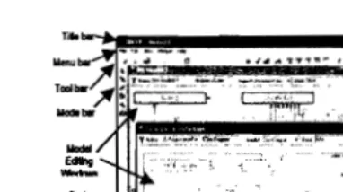
Having completed and interpreted the physical metarnodels discussed in the previous section, the newly generated tool environment of the BROOD modelling paradigm that is based on the GME meta-paradigm is now ready to be used. In its main window, which is shown in Figure 3, the name of the currently opened project is displayed on the Title bar. Menu bar and tool bar allow access to certain commands provided by the environment. The buttons to execute the interpreters are located at the right-end of the tool bar. Mode bar contains selection and connection buttons. Model editing window is used to visually construct and edit the models. Users may add the model component, which is called part in GME, by selecting it from part browser window and dragging it to the model editing window. Each model editing window has its own title bar that displays the name of the currently edited model. The attributes of the model can be added or modified using the form-based attribute browser window. Users may navigate the models in the current project using the tree structure view provided by model browser window.
. .: ; ' 1lIdI
_.
...
...
F
Jilid 20, Bil. 2 (Disember 2008) Jumal Teknologi Maklumat • RPEntriesSingleton: project.allInstancesOf(RulePhraseEntries)
->size <2
• NotEmptyTemplateID: self.templateID.trimO<>1111
• UniqueRulePhrase:·
project.alllnstancesOf(Cardinality) -> select( c
I
c.name==self.name ) -> size== IIn the above examples,RPEntriesSingletoncontrols the project to only have a single rule
phrase entries model. This restriction may simplify the maintenance of a large number
of unique rule phrases. The second constraint, i.e.NotEmptyTemplatelD,checks the
templatelDattribute of the connected business rule instance to ensure that the value is
not empty.Itis important in ensuring thattempiatelDalways has a value since it is
frequently used in the developed interpreters for instance the generated business rule
statement depends on the selectedtempiatelD.The last constraint in the above examples,
namelyUniqueRulePhrase,was attached to all rule phrase atoms or objects to ensure that
each rule phrase is unique. A unique rule phrase name may avoid the business user
confusion on the meaning of the selected rule phrases in composing a business rule.
4.BROODTOOLFEATURES
Having completed and interpreted the physical metamodels discussed in the previous section, the newly generated tool environment of the BROOD modelling paradigm that is based on the GME meta-paradigm is now ready to be used. In its main window, which is shown in Figure 3, the name of the currently opened project is displayed on the Title bar. Menu bar and tool bar allow access to certain commands provided by the environment. The buttons to execute the interpreters are located at the right-end of the tool bar. Mode bar contains selection and connection buttons. Model editing window is used to visually construct and edit the models. Users may add the model component, which is called part in GME, by selecting it from part browser window and dragging it to the model editing window. Each model editing window has its own title bar that displays the name of the currently edited model. The attributes of the model can be added or modified using the form-based attribute browser window. Users may navigate the models in the current project using the tree structure view provided by model browser window.
Figure 3. The generated BROOD tool environment
4.1 Model Editing
There are four main types of models can be created using the BROOD tool: rule phrase entries, business rule, class diagram, and statechart diagram. The simplest way to create a new model is to right-click the project name in the model browser window and select Insert Model command from the pop-up menu. Users may select the type of the model to be created from the displayed choices. As the type is selected, a new item with the default model name is inserted in the tree view of the current project. By double-clicking on the model name, the model editing window is displayed and the model is now ready for editing.
4.2 Adding a New Business Rule
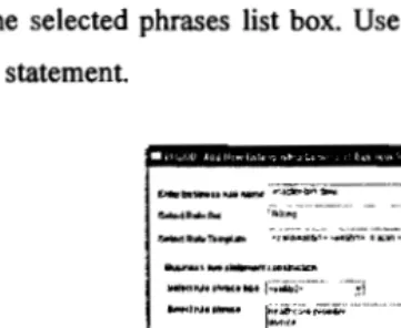
The Add Business Rule (ABR) module was developed to assist user in adding a new business rule to the selected business rule model. The ABR module performs two main tasks: business rule composition and software design updating. In business rule composition, rule phrases are used as the building blocks to construct a new business rule statement. Majority of the rule phrases are available from the rule phrase entries. For certain types of rule phrases, such as value and number, they are not stored in the rule phrase entries. Instead, their values are entered during rule composition and stored as the rule attributes. With regard to updating the software design, the ABR module automatically updates the software design information to correspond with the newly composed rule. The action taken depends on the selected rule type and template. For example, the attribute and relationship constraints are directly linked to the attribute and relationship in the class diagram.
As the ABR is invoked, it shows the selection window that allows a user to specify the type of the business rule to be added. A business rule composition window is displayed after the user made the choice. As the example, the window that is displayed when the user chooses a relationship constraint is shown in Figure 4. User may enter the name and choose
lilid 20, Bil.2 (Disember 2008) lurna\ Teknologi Maklumat
Figure 3. The generated BROOD tool environment
4.1 Model Editing
There are four main types of models can be created using the BROOD tool: rule phrase entries, business rule, class diagram, and statechart diagram. The simplest way to create a new model is to right-click the project name in the model browser window and select Insert Model command from the pop-up menu. Users may select the type of the model to be created from the displayed choices. As the type is selected, a new item with the default model name is inserted in the tree view of the current project. By double-clicking on the model name, the model editing window is displayed and the model is now ready for editing.
4.2 Adding a New Business Rule
The Add Business Rule (ABR) module was developed to assist user in adding a new business rule to the selected business rule model. The ABR module performs two main tasks: business rule composition and software design updating. In business rule composition, rule phrases are used as the building blocks to construct a new business rule statement. Majority of the rule phrases are available from the rule phrase entries. For certain types of rule phrases, such as value and number, they are not stored in the rule phrase entries. Instead, their values are entered during rule composition and stored as the rule attributes. With regard to updating the software design, the ABR module automatically updates the software design information to correspond with the newly composed rule. The action taken depends on the selected rule type and template. For example, the attribute and relationship constraints are directly linked to the attribute and relationship in the class diagram.
As the ABR is invoked, it shows the selection window that allows a user to specify the type of the business rule to be added. A business rule composition window is displayed after the user made the choice. As the example, the window that is displayed when the user chooses a relationship constraint is shown in Figure 4. User may enter the name and choose
the ruleset for the new business rule. The rule template must be chosen from the listed choices. As the template is selected, the rule phrase type combo box is populated according to the selected template. The available rule phrases are displayed in the rule phrase list box. User only needs to double-click the desired rule phrase to select it. The selected rule phrase is ' inserted in the selected phrases list box. Use construct rule button to display the composed business rule statement.
EIIiIr"''''",_~
.-":~:b'i-"'---~.-'-"'ll~'; _. ----~l
_1tuIoo~ ...._ :f...lUlIlo1 . . . .Ih"I • •a:.II'1.,IOO ••j ...,tll!(,""·_l· ~i
~. _''--''llIIUWW:''
lIel,,"""'~"'Mr'F;.·;~··-- ·'-:~l
Figure 4. Adding a new relationship constraint
Having composed the business rule statement, the business rule is now ready to be added to the currently opened business rule model. As mentioned above, the ABR module does not only compose business rule but it also performs a trickier task Le. updating the design components according to the newly composed business rule. In the above relationship constraint example, the relationship constraint atom is firstly created for the new business rule and it is consequently added to the current model after a user clicked the Add Business Rule button. Next, it searches for the existing association relationships between the first and second entities. Then, it displays the pop-up window that allow user to link business rule to one of the existing associations or create a new association. Once the association is selected or created, the cardinalities and role information form the business rule is transformed to their respective attributes of the selected association.
The creation of a new connection is trickier when the source and destination classes are not located in the same diagram or the destination class is a class copy. To solve this problem, the ABR module traverse all models and checks both classes and class copies to find the source and destination classes. If the classes are located in the same class diagram, it will create a connection from the source class to the destination class or class copy. However, if the classes are located in different diagram, the ABR module must create a new class copy as the destination for the new connection. The source codes that implement this task is shown in the following code snippet:
Jilid 20, Bil. 2 (Disember 2008) Jurnal Teknologi Maklumat the ruleset for the new business rule. The rule template must be chosen from the listed choices. As the template is selected, the rule phrase type combo box is populated according to the selected template. The available rule phrases are displayed in the rule phrase list box. User only needs to double-click the desired rule phrase to select it. The selected rule phrase is' inserted in the selected phrases list box. Use construct rule button to display the composed business rule statement.
Figure 4. Adding a new relationship constraint
Having composed the business rule statement, the business rule is now ready to be added to the currently opened business rule model. As mentioned above, the ABR module does not only compose business rule but it also performs a trickier task i.e. updating the design components according to the newly composed business rule. In the above relationship constraint example, the relationship constraint atom is firstly created for the new business rule and it is consequently added to the current model after a user clicked the Add Business Rule button. Next, it searches for the existing association relationships between the first and second entities. Then, it displays the pop-up window that allow user to link business rule to one of the existing associations or create a new association. Once the association is selected or created, the cardinalities and role information form the business rule is transformed to their respective
J
attributes of the selected association.
I
The creation of a new connection is trickier when the source and destination classes are not
1
located in the same diagram or the destination class is a class copy. To solve this problem, the IABR module traverse all models and checks both classes and class copies to find the source 'J and destination classes. If the classes are located in the same class diagram, it will create a : connection from the source class to the destination class or class copy. However, if the classes are located in different diagram, the ABR module must create a new class copy as the destination for the new connection. The source codes that implement this task is shown in the following code snippet:
II--Create a new Association connection where both classes in the same class diagram if(classDiagram I == classDiagram2)
{ if (!dstClass->GetNameO.Compare("NULL") = 0)
conn = classDiagram 1-> CreateNewConnection("Association",srcClass,dstClass); else
conn = classDiagram 1->
CreateNewConnection("Association", srcClass,dstClassRet);
conn->SetName(linkedRelationship); conn->SetAttribute(srcCardAtt,
designCard 1); conn->SetAttribute(dstCardAtt,
designCard2); conn->SetAttribute(srcRoleAtt,
roIePhrase); } else
II Create a new Association where srcClass and II dstClass resided in different class diagram { CBuilderModelReference *newClassRef=
classDiagrarn 1->
CreateNewModeIReference("ClassCopy",dstClass); newClassRef->SetName(dstClass->GetNameO);
conn = classDiagrarn 1->
CreateNewConnection("Association" srcClass,newClassRet);
conn->SetName(linkedRelationship);
conn->SetAttribute(srcCardAtt,designCardI); conn->SetAttribute(dstCardAtt,designCard2); conn->SetAttribute(srcRoleAtt,rolePhrase);
}
4.3 Performing Business Rule Changes
The ultimate aim of the BROOD tool is to simplify the implementation of business rule
changes. The Modify Business Rule (MBR) module was developed to assist tool users in
performing this task. The MBR module starts with displaying a tree structure of the rulesets
and business rule statements of the currently opened business rule model. User may browse
the business rule statement and select the statement to be modified. After the statement is
selected, the MBR module traverse the business rule model to obtain the business rule object
(atom), create a new window according to the type of the selected rule, and populating the
window with the current business rule information.
Figure 5 shows the window when a user select 'WHEN 30 day after the creation date ofthe
invoice IF current balance of the invoice is greater than 0 THEN trigger issue the first
reminder' rule statement from the tree view.
Jilid 20, Bil.2 (Disember 2008) Jurnal Teknologi Maklumat
II--Createa new Association connection where both classes in the same class diagram if(classDiagram I == classDiagram2)
{ if (!dstClass->GetNameO.Compare("NULL")= 0)
conn = classDiagram 1-> CreateNewConnection("Association",srcClass,dstClass); else
conn = classDiagram 1->
CreateNewConnection(tIAssociation", srcClass,dstClassRef);
conn->SetName(linkedRelationship); conn->SetAttribute(srcCardAtt,
designCardl); conn->SetAttribute(dstCardAtt,
designCard2); conn->SetAttribute(srcRoleAtt,
ro IePhrase); } else
IICreate a new Association where srcClass and
IIdstClass resided in different class diagram { CBuilderModelReference *newClassRef=
classDiagram 1->
CreateNewModeIReference("ClassCopy",dstClass); newClassRef->SetName(dstClass->GetNameO);
conn = classDiagram 1->
CreateNewConnection("Association" srcClass,newClassRet);
conn->SetName(linkedRelationship); conn->SetAttribute(srcCardAtt,designCard I); conn->SetAttribute(dstCardAtt,designCard2); conn->SetAttribute(srcRoleAtt,rolePhrase); }
4.3Performing Business Rule Changes
The ultimate aim of the BROOD tool is to simplify the implementation of business rule changes. The Modify Business Rule (MBR) module was developed to assist tool users in performing this task. The MBR module starts with displaying a tree structure of the rulesets and business rule statements of the currently opened business rule model. User may browse the business rule statement and select the statement to be modified. After the statement is selected, the MBR module traverse the business rule model to obtain the business rule object (atom), create a new window according to the type of the selected rule, and populating the window with the current business rule information.
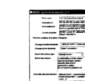
Figure5 shows the window when a user select 'WHEN 30 day after the creation date of the invoice IF current balance of the invoice is greater than 0 THEN trigger issue the first reminder' rule statement from the tree view.
[_NIl"" ~~~"'=;.,
.._.
---I~J.
__
e.~=:::~;==::::::=..""".-(:u.._ ..._ ==!:~l"""""'.""""_
~1"'I.otlltllOll_ _~
O:~_"l'l.~"""~ ...,,,,,r"";'~""'01001*,"·""'I_" .!] ~-""".... r;;i.;-"w-..;;--·---·---·--·-.!l ~
W_I_ ... .•_ ~ ~
~"",~lIlI
f==::--··¥..·- ...
r ' j c-,...,.a:..,~ft'o
~
l::-"'~.,~~•• I ._ ..,
; n. _ _ ,"
¢y.1lI"".-GH ·.~I"'"_~"'. .
: ~ ,~.---
...
_._
...
-
..
~
..:,..._,_
...
-~--
...
• lIt1. .lNI...,r~:i;ti.-·_·"3 r--. il
~_:'-"""" .::J ....-i~.!'j
Figure 5. Modifying an action 'assertion business role
As shown in Figure 5, the window is initially populated with the existing rule phrases and templates of the selected business rule statement. User may modify the event, condition, action, and linked software design components using this window. With regard to the condition and action modification, user may change their templates by selecting one of the listed choices in the provided combo boxes. After the Confirm Template button is clicked, the rule phrase type combo box is populated with the names of the rule phrase types found in the selected templates. User may select a rule phrase type to change from rule phrase type combo box. As the rule phrase type is selected, its instances from rule phrase entries are listed in the rule phrase list box. User may select the item by double-clicking. If the user select <value> from the rule phrase type combo box, the edit box and Insert Value button will be activated to allow the user to enter the value of <value>. The selected role phrases are displayed in the selected rule phrases list box. User may view the changed rule statement using the View Changed Rule button.
Upon clicking the Commit Change button, the business rule changes are automatically propagated to the linked software design components. The specification of event, condition, and action of the business rule are transformed to event, guard, and action of the linked state transition in the selected statechart diagram. The business rule may also be linked to the operation that performs the specified action on the occurrence of the event and the satisfaction of the condition. For example, this action assertion is implemented in addReminderListItemO operation of the InvoiceApp class that adds the paymaster into the list of the category I past due paymasters when the payment is not received within 15 days from the invoice date. The list is subsequently used to manually issue the first reminder letters. In this example, the changed business rule specification is transformed to the design specification and automatically inserted in the specification of the addReminderListItemO operation. In certain
Jilid 20, Bil. 2 (Disember 2008) Jumal Teknologi Maklumat
n
is to chanl of days ofl by selecting edit box, an(~,1
event phrase may click
¢I,o...~ · ...I...·_~IIl. .
:~~..
~,.---."'~._,-
...
""'-(:u.._..._ e=!:~l"----."""-,...""I.otllMOII _ _~
O:~_. .n.""'''''':<....,\,f&r--.;.~...0geI*'. . . .
l_...
.!]~_____ r~i';;-.w_,,;;-"-·--'--·-·-·--·--.!:! ~
...._I .... ,...~ ~
~"...~~.
f==..::=--···- ...
:...,.d:60.,..."1,----
. .I
!~~~~~.. ~,
·llII _ _ 'M··
...
-
...
...
_
-_
...
....--......
_-
..
-~--
...
• lIt1 . .~~r~:iMi.----'·_·"3_ ...~ iJ
... _c,_1IolcJ -:'!j . . . ...-\~..!j
Figure 5. Modifying an action 'assertion business role
As shown in Figure 5, the window is initially populated with the existing rule phrases and templates of the selected business rule statement. User may modify the event, condition, action, and linked software design components using this window. With regard to the condition and action modification, user may change their templates by selecting one of the listed choices in the provided combo boxes. After the Confirm Template button is clicked, the rule phrase type combo box is populated with the names of the rule phrase types found in the selected templates. User may select a rule phrase type to change from rule phrase type combo box. As the rule phrase type is selected, its instances from rule phrase entries are listed in the rule phrase list box. User may select the item by double-clicking. If the user select <value>
from the rule phrase type combo box, the edit box and Insert Value button will be activated to allow the user to enter the value of<value>. The selected role phrases are displayed in the selected rule phrases list box. User may view the changed rule statement using the View Changed Rule button.
Upon clicking the Commit Change button, the business rule changes are automatically propagated to the linked software design components. The specification of event, condition, and action of the business rule are transformed to event, guard, and action of the linked state transition in the selected statechart diagram. The business rule may also be linked to the operation that performs the specified action on the occurrence of the event and the satisfaction of the condition. For example, this action assertion is implemented in addReminderListItemO operation of the InvoiceApp class that adds the paymaster into the list of the category I past due paymasters when the payment is not received within 15 days from the invoice date. The list is subsequently used to manually issue the first reminder letters. In this example, the changed business rule specification is transformed to the design specification and automatically inserted in the specification of the addReminderListItemO operation. In certain
occasions, user may need to change the linked design components. However, changing the linked software design components is infrequently happened during the software operation.
User is also allowed to change the event specification by clicking the Change Event button. As the button is clicked, the window shown in Figure 6 is displayed.
...,.""'n.,...IIlM ...,I.~IICIlIl\...IiII1lon_1
r.tIIngt-Pi'fIIII*""-'" ~• ..,.n,;;;;...~$It""""~-·---3
c ,
.,...tt__,... r;-....---·-3
0MdM-1lnM r~·-" l ... ~w...-.·l
1=
!".
"'....
_<W_~_:=:;.
~·"'...04tTru- M il"Nft 0... If...
Figure 6. Modifying an event rule phrase
As shown in Figure 6, the currently selected template and rule phrases are displayed on the window. User is allowed to change the template, however it must be carefully done since the event might be used by other action assertion rules. The most frequent change to an event specification is to change the value of its rule phrase. For example, a user may wish to change the number of days of a category 1 past due invoice from 30 to 15 days. This can be done by very easily by selecting <number> from the sub-phrase type combo box, enter the value in the <number> edit box, and press the Insert Number button. Next, user may choose either to type in a new event phrase or automatically generate based on the modified event specification. Finally, user may click Commit Change button to save the event changes and return to the caller window. The event phrase and rule statement in the caller window will be updated accordingly.
6. SUMMARY AND CONCLUSION
The design and implementation of the tool that supports the BROOD approach was described in this paper. The BROOD tool was developed using the configurable GME modelling environment. The physical metamodel, which is the implementation version of the BROOD metamodel discussed in section 2, were developed for all BROOD models such as rule phrase entries, business rule specification, class diagram, and statechart diagram. A number of simple modelling constraints were also created and attached to the particular metamodel components. The defined metamodels were used in generating the BROOD tool
Jilid 20, Bil.2 (Disember 2008) Jumal Teknologi Maklumat
occasions, user may need to change the linked design components. However, changing the linked software design components is infrequently happened during the software operation.
User is also allowed to change the event specification by clicking the Change Event button. As the button is clicked, the window shown in Figure 6 is displayed.
~""''nIeIlllllllJMM''''_.'''IIIIKII,''''''''ICIlIl\...IIIIIIn'''1 ~ ~7";\";';;;;"·~~;:;;;::-·_---3
CIlWl MI
.... tt __ , .. . . .~tni---"3
DldltM-1lltaM r=:.-·"""- f..,..~w...-.·i
I§F
~..._...a ::;::r;;.~
<1I'l•••D-lIIltTl'Il"" M il.ilNfton_III'h
Figure 6. Modifying an event rule phrase
As shown in Figure 6, the currently selected template and rule phrases are displayed on the window. User is allowed to change the template, however it must be carefully done since the event might be used by other action assertion rules. The most frequent change to an event specification is to change the value of its rule phrase. For example, a user may wish to change the number of days of a category I past due invoice from 30 to 15 days. This can be done by very easily by selecting <number> from the sub-phrase type combo box, enter the value in the <number> edit box, and press the Insert Number button. Next, user may choose either to type in a new event phrase or automatically generate based on the modified event specification. Finally, user may click Commit Change button to save the event changes and return to the caller window. The event phrase and rule statement in the caller window will be updated accordingly.
6.SUMMARY AND CONCLUSION
The design and implementation of the tool that supports the BROOD approach was described in this paper. The BROOD tool was developed using the configurable GME modelling environment. The physical metamodel, which is the implementation version of the BROOD metamodel discussed in section 2, were developed for all BROOD models such as rule phrase entries, business rule specification, class diagram, and statechart diagram. A number of simple modelling constraints were also created and attached to the particular metamodel components. The defined metamodels were used in generating the BROOD tool
86
•
environment. The chosen GME was found very convenient in experimenting with the implementation feasibility and technical aspect of the BROOD metamodel since it is highly configurable in generating a new modelling paradigm. The BROOD tool provides a number offunctionalities in assisting the development and evolution activities in the BROOD process. These functionalities are provided using the GME-generated graphical model editor and the developed fonn-based modules. The developed modules are provided to maintain rule phrase entries, compose new business rules, and perfonn business rule changes. The fonn-based graphical user interfaces of these modules facilitate the composition of a new business rule statement using the existing rule phrases in the rule phrase entries. They also assist the linking of business rules to their related software design components. These modules automate the propagation of the business rule changes to software design via the extensive use of the GME programming facilities.
As a conclusion, the BROOD tool simplifies the tedious, error-prone, and time-consuming task of linking and propagating the business rule changes to software design components. A business rule can be changed by changing its rule phrases and the changes are automatically propagated to the related software design components. Apart from that, the BROOD tool provided useful feedbacks in the improvement of the technical aspect of the BROOD metamodel and templates.
REFERENCES
[I] P. Grubb and A. A. Takang, Software Maintenance: Concepts and Practice. Singapore: World Scientific
Publishing, 2003.
[2] M. M. Lehman, "Laws of Software Evolution Revisited," presented at European Workshop on Software
Process Technology '96,1997.
[3] A. Finkelstein and J. Kramer, "Software Engineering: A Roadmap," presented at Conference on the Future
of Software Engineering, Limerick, Ireland, 2000.
[4] I. Rouvellou, L. Degenaro, K. Rasmus, D. Ehnebuske, and B. McKee, "Extending Business Objects with
Business Rules," presented at 33rd International Conference on Technology of Object-Oriented Languages
and Systems ( TOOLS Europe 2000), Mont Saint-Michell St-Malo, France, 2000.
[5] N. Chapin, 1. E. Hale, K. M. Khan, 1. F. RamiI, and W. Tan, "Types of software evolution and software
maintenance," Journal of Software Maintenance and Evolution: Research and Practice, vol. 13, pp.' 3·30,
2001.
[6] L. Andrade and 1. Fiadeiro, "Coordination Technologies for Managing Infonnation System Evolution,"
presented at 13th Conference on Advanced Information Systems Engineering, Interlaken, Switzerland, 200 I.
[7] D. Hay and K. A. Healy, "Defining Business Rules - What Are They Really?," the Business Rules Group
Rev 1.3, July 2000.
[8] H. Herbst, Business Rule-Oriented Conceptual Modeling. Germany: Physica-Verlag, 1997.
[9] H. Herbst, "Business Rules in Systems Analysis: A Meta-model and Repository System," lriformation
Systems, vol. 21, pp. 147-166,1996.
Jilid 20, Bil. 2 (Disember 2008) Jurnal Teknologi Maklumat
86
environment. The chosen GME was found very convenient in experimenting with the implementation feasibility and technical aspect of the BROOD metamodel since it is highly configurable in generating a new modelling paradigm. The BROOD tool provides a number offunctionalities in assisting the development and evolution activities in the BROOD process. These functionalities are provided using the GME-generated graphical model editor and the developed form-based modules. The developed modules are provided to maintain rule phrase entries, compose new business rules, and perform business rule changes. The form-based graphical user interfaces of these modules facilitate the composition of a new business rule statement using the existing rule phrases in the rule phrase entries. They also assist the linking of business rules to their related software design components. These modules automate the propagation of the business rule changes to software design via the extensive use of the GME programming facilities.
As a conclusion, the BROOD tool simplifies the tedious, error-prone, and time-consuming task of linking and propagating the business rule changes to software design components. A business rule can be changed by changing its rule phrases and the changes are automatically propagated to the related software design components. Apart from that, the BROOD tool provided useful feedbacks in the improvement of the technical aspect of the BROOD metamodel and templates.
REFERENCES
[I] P. Grubb and A. A. Takang.Software Maintenance: Concepts and Practice. Singapore: World Scientific
Publishing, 2003.
[2] M. M. Lehman, "Laws of Software Evolution Revisited," presented at European Workshop on Software
Process Technology '96,1997.
[3] A. Finkelstein and J. Kramer, "Software Engineering: A Roadmap," presented at Conference on the Future
of Software Engineering, Limerick, Ireland, 2000.
[4] I.Rouvel1ou,L. Degenaro,K. Rasmus, D. Ehnebuske, and B. McKee, "Extending Business Objects with
Business Rules," presented at 33rd International Conference on Technology of Object-Oriented Languages
and Systems ( TOOLS Europe 2000), Mont Saint-Michell St-Malo, France, 2000.
[5] N. Chapin, J. E. Hale, K.M. Khan, J. F. Ramil, and W. Tan, "Types of software evolution and software
maintenance,"Journal of Software Maintenance and Evolution: Research and Practice,vol. 13, pp.' 3-30,
2001.
[6] L. Andrade and J. Fiadeiro, "Coordination Technologies for Managing Infonnation System Evolution,"
presented at 13th Conference on Advanced Infonnation Systems Engineering, Interlaken, Switzerland, 200I.
[7] D. Hay and K. A. Healy, "Defining Business Rules - What Are They Real1y?," the Business Rules Group
Rev 1.3, July 2000.
[8] H. Herbst,Business Rule-Oriented Conceptual Modeling.Gennany: Physica-Verlag, 1997.
[9] H. Herbst, "Business Rules in Systems Analysis: A Meta-model and Repository System," Information
Systems,vol. 21, pp. 147-166, 1996.
[10] T. Morgan, Business Rules and Information Systems: Aligning IT with Business Goals. Boston, MA:
Addison-Wesley, 2002.
[II] R. G. Ross, Principles of the Business Rule Approach. Boston, USA: Addison-Wesley, 2003.
[I2] D. Riehle, M. Tilman, and R. Johnson, "Dynamic Object Model," Dept. of Computer Science, Washington
University WUCS-00-29, 2000.
[13] J. W. Yoder, F. Balaguer, and R. Jolmson, "Adaptive Object Models for Implementing Business Rules,"
presented at Third Workshop on Best-Practices for Business Rules Design and Implementation, Conference
on Object-Oriented Programming, Systems, Languages, and Applications (OOPS LA 2001), Tampa Bay,
Florida., USA, 200 I.
[I4] L. Andrade and J. Fiadeiro, "Evolution by Contract," presented at ACM Conference on Object-Oriented
Programming, Systems, Languages, and Applications 2000, Workshop on Best-practice in Business ,Rules
Design and Implementation, Minneapolis, Minnesota USA, 2000.
[IS] I. Rouvellou, I. Degenaro, K. Rasmus, D. Ehnebuske, and B. McKee, "Externalizing Business Rules from
Enterprise Applications: An Experience Report," presented at Conference on Object-0riented Programming,
Systems, Languages, and Applications, Denver, Colorado, 1999.
[16] OMG, "UML Specifications," 1.5 ed: Object Management Group, 2003.
[17] W. M. N. Wan Kadir and P. Loucopoulos, "Relating Evolving Business Rules to Software Design," Journal
ofSystems Architecture, vol. 50, pp. 367-382,2004.
[18] W. M. N. Wan Kook and R. Md Shariff, "Metamodel and Process for Design-Level Object-0riented
Software Evolution," presented at the 1st Malaysian Software Engineering Conference (MySEC'05), Tg
Bungah, Pulau Pinang, 2005.
[19] A. Ledeczi, M. Maroti, A. Bakay, G. Karsai, J. Garrett, C. Thomason, G. Nordstrom, J. Sprinkle, and P.
Volgyesi, "The Generic Modeling Environment," presented at Workshop on Intelligent Signal Processing,
Budapest, Hungary, 2001.
[20] VU, "GME 3 User's Manual," 3.0 ed: Institute for Software Integrated System, Vanderbilt University, 2003.
[21] A. Ledeczi, P. Volgyesi, and G. Karsai, "Metamodel Composition in the Generic Modeling Environment,"
presented at 15th European Conference on Object-Oriented Programming, University Eiitvos Lorand,
Budapest, Hungary, 2001.
[22] OMG, "OMG Unified Modeling Language Specification," 1.4 ed: Object Management Group, 2001.
Jilid 20, Bil.2 (Disember 2008) Jurnal Teknologi Maklumat
[10] T. Morgan, Business Rules and Information Systems: Aligning IT with Business Goals. Boston, MA:
Addison-Wesley, 2002.
[II] R. G. Ross,Principles ofthe Business Rule Approach.Boston, USA: Addison-Wesley, 2003.
[12] D. Riehle, M. Tilman, and R. Johnson, "Dynamic Object Model," Dept. of Computer Science, Washington
University WUCS-00-29, 2000.
[13] J. W. Yoder, F. Balaguer, and R. Johnson, "Adaptive Object Models for Implementing Business Rules,"
presented at Third Workshop on Best-Practices for Business Rules Design and Implementation, Conference
on Object-Oriented Programming, Systems, Languages, and Applications (OOPSLA 2001), Tampa Bay,
Florida, USA, 200I.
[14] L. Andrade and J. Fiadeiro, "Evolution by Contract," presented at ACM Conference on Object-Oriented
Programming, Systems, Languages, and Applications 2000, Workshop on Best-practice in Business ,Rules
Design and Implementation, Minneapolis, Minnesota USA, 2000.
[15] I.Rouvellou,I.Degenaro, K. Rasmus, D. Ehnebuske, andB.McKee, "Externalizing Business Rules from
Enterprise Applications: An Experience Report," presented at Conference on Object-0riented Programming,
Systems, Languages, and Applications, Denver, Colorado, 1999.
[16] OMG, "UML Specifications," 1.5 ed: Object Management Group, 2003.
[17] W. M. N. Wan Kadir and P. Loucopoulos, "Relating Evolving Business Rules to Software Design,"Journal
ofSystems Architecture,vol. 50, pp. 367-382,2004.
[18] W. M. N. Wan Kook and R. Md Shariff, "Metamodel and Process for Design-Level Object-Qriented
Software Evolution," presented at the 1st Malaysian Software Engineering Conference (MySEC'05), Tg
Bungah, Pulau Pinang, 2005.
[19] A. Ledeczi, M. Maroti, A. Bakay, G. Karsai,J.Garrett, C. Thomason, G. Nordstrom, J. Sprinkle, and P.
Volgyesi, "The Generic Modeling Environment," presented at Workshop on Intelligent Signal Processing,
Budapest, Hungary, 2001.
[20] VU, "GME 3 User's Manual," 3.0 ed: Institute for Software Integrated System, Vanderbilt University, 2003.
[21] A.Ledeczi, P. Volgyesi, and G. Karsai, "Metamodel Composition in the Generic Modeling Environment,"
presented at 15th European Conference on Object-Oriented Programming, University Eotvos Lorand,
Budapest, Hungary, 2001.
[22] OMG, "OMG Unified Modeling Language Specification," 1.4 ed: Object Management Group, 2001.