a
Corresponding author: [email protected]
What can be done with microbubbles generated by a fluidic oscillator?
(survey)
Václav Tesa1,a
1
Institute of Thermomechanics v.v.i., Czech Academy of Sciences Dolejškova 5, 182 00 Praha-Kobylisy, Czech Republic
Abstract. Recently discovered possibility of generating sub-millimetre bubbles by means of pulsating the inlet gas flow by a fluidic oscillator has opened a way to many interesting and advantageous engineering applications. Some of them have been known before, but were too inefficient and nearly forgotten. Now they deserve discussing in the new perspective. Other, applications, new ones, appear now in literature at a rapid pace. This paper, by providing a survey of already existing possibilities and advantages, aims at providing the readers an inspiration for their own developments.
1 Introduction
Two-phase operations between gas and liquid in chemical and process engineering are often performed in the form of the gas blown into the liquid as bubbles. It has been always recognised that many (if not all) of these processes would be more efficient if the given gas volume is distributed into a large number of smaller bubbles - because this means an increase of the total collective area of the mutual contact surface between the phases. Another potential advantage of the smaller size would be their slow rise in the liquid, making available a longer contact time. There are other advantages, nowadays discovered and reported increasingly often. Until recently it was, however, practically impossible to use them. Despite all the attempts, there has been almost
Figure 1 Three size classes of gas bubbles in a liquid. Until recently, it was possible to generate efficiently only the large, millimetre-sized bubbles. Little is known at the small size end of the spectrum about the rather enigmatic nano-bubbles [1], less than 1 nm. Between them are microbubbles, discussed in the present article. Generating them became possible with fluidic oscillators.
Figure 2 A typical example of the microbubble paradox: small air flow pores – here of equivalent exit diameter only
0.12 mm – do not produce correspondingly small bubbles: average bubble size in this case was 5.7 mm.
always a failure due to too large bubble size. The desirable sub-millimetre microbubbles, Fig. 1, could not be produced economically.
working as expected or were ineffective and hence not acceptable economically.
The situation has changed after a chance discovery of the present author, then staying at the University of Sheffield, U. K.. He could generate surprisingly small bubbles with a standard aerator by placing into the gas inlet lines a simple and inexpensive fluidic oscillator. This device [3] was actually designed for a wholly different purpose (separation control of flow past a wind-tunnel model). In a series of simple experiments the pulsation generated in the airflow under some conditions (gas flow rates and oscillation frequencies were to be closely adjusted) the generated bubbles were indeed in the desirable sub-millimetre microbubble range.
2 Basic idea of fluidic oscillators
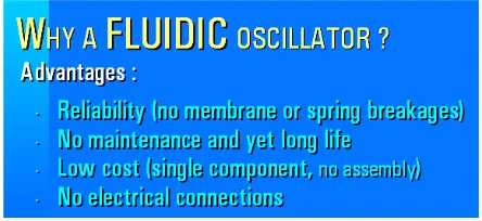
This solution of the microbubble problem, for which was later obtained a patent [4], was soon followed by similar positive experience of other researchers. It should be said that the basic idea of oscillation as the way to smaller bubbles is not totally new and was tried earlier. It was the advantages offered by fluidic oscillators, Fig. 3, that opened the way to the new possibilities.Figure 3 What has now really opened the road towards the discussed applications of microbubbles are the advantages, here listed, that result from the absence of mechanical (moving or deformed) components in fluidics.
There are two essential components of which the fluidic oscillators consist. One of them is fluid flowfield with amplification properties. This is obtained by shaping the cavities for the flow so that it possesses a sensitive spot. The second component is introduction of a negative feedback.
The amplification means that a quite weak input flow causes a substantial overall change of the whole flowfield. Once the importance of such sensitive spots in fluid flow became recognised, they were discovered present in many flow cases. A typical example of such sensitivity may be a laminar flow with Reynolds number adjusted to critical transition conditions. In this case the input flow causes a transition into turbulence – with character quite different than the original laminar flow. This particular turbulisation sensitivity is today rarely used in fluidic amplifiers (since it is too sensitive even to various mechanical or acceleration disturbances and hence difficult to adjust). The best experience has been so far obtained with another sensitive flow case: the deflection of a jet generated by flow from a nozzle by input flow directed to it perpendicularly.
Figure 4 Basic configuration principle of fluidic oscillators. The key component is a fluidic amplifier, responding to a small input by substantial change in the output flow. Oscillation is then generated by addition of feedback loop. It destabilises the conditions by returning back a part of output fluid flow to act negatively on the flow in the control terminal X.
This jet deflection is currently the common working principle in devices specifically made to serve as fluidic amplifiers. Basic principles of their configuration are in Fig. 4. There are several terminals for the fluid flow into and out the amplifier. At left in Fig. 4 is supply terminal
S for bringing into the device a more or less constant fluid flow. Then there is the input terminal X. Into it enters the weak signal that is to be amplified and generate the change – decrease – in the output flow in the terminal
Y. Very often (though not absolutely necessarily) there is also a vent terminal V through which leaves the fluid that is directed away from the output terminal Y.
Without any control flow in X in the jet-deflection type amplifier the whole flow coming through S is allowed to continue into Y. There are amplifiers with proportional character of the response: the higher is the magnitude of the control flow admitted into X, the more is the supplied flow deflected into the vent V. Many amplifiers used in fluidic oscillators respond differently: by switching the flow between Y and V. This is achieved by using the Coanda effect of the main flow attaching to a nearby attachment wall.
The other necessary effect, which turns the amplifier into the oscillator, is feedback action. It is present in such self-excited oscillation processes like the "friction tones" in trailing vortex streets past bluff bodies [5], but there it is not immediately apparent. Its typical form in fluidic oscillators is a flow channel connecting the output terminal Y with the control inlet X, as schematically presented in Fig. 4. The feedback enables a part of the output flow from Y returning back into X. There are two aspects this feedback must have if it is to be of use in an oscillator. First, the control action on the main flow coming from S must be such that an increasing control flow into X causes a decrease (and not increase) of the output flow in Y. The other aspect - which may be also fulfilled quite automatically - is the presence of some phase delay acting in the loop. This may be simply due to the time it takes to the fluid flow to get from Y to X.
Figure 5 An example of the simplest fluidic oscillator. It consists of cavities and channels made – as now usual — by photoetching in a thin flat plate. The jet, generated in the supply nozzle, attaches by the Coanda effect to the preferred attachment wall p – from which it is switched away into V by the feedback flow coming through the loop.
First, it is simple so that the character of fluid flows may be in Fig. 5 easily imagined. Second, it was exactly this configuration which in the schematic representation - Fig. 6 - was originally accompanying the description of invention in the Patent [4].
Characteristically for present-day fluidics, the amplifier of the oscillator in Fig. 5 is made by etching the channels for fluid flow in a small rectangular plane plate. For closing the channels (and thus preventing the fluid in them from escaping), the cavities are covered on top and bottom by similarly shaped rectangular flat cover plates. The terminals S, X, Y, and V were in this case arranged as holes drilled in one cover plate so that the fluid enters them perpendicularly.
Let us follow in Fig. 5 the air flow entering through the supply terminal S. By issuing from the supply nozzle the air forms a jet, the flow of which is shown in Fig. 5 as the curved blue line. By the Coanda attachment
Figure 6 Microbubble generator principle. This drawing was originally prepared for the Patent Application [4].
mechanism, this jet attaches to the attachment wall p and is led into the output terminal Y. This channel leading into Y is shaped as a diffuser — i.e. its cross-section area gradually increases in the flow direction. Note that this is an opposite effect to what happens in the nozzle connected to S, where the cross-section area decreases in the direction of flow. It input pressure energy is in the nozzle gradually converted into kinetic energy. Then, in the diffuser, the air flow is slowed down, its pressure increases. Thus in the interaction region near the wall p there is a pressure minimum, with pressure lower than in
Y. It is this pressure difference by which the air flow is driven through the feedback loop channel.
Upon arrival into X the feedback flow impinges upon the main jet at a right angle. This forces the jet to stop its attaching to the attachment wall p and separate. All the flow, from S as well as from X is thus diverted into the vent V. This, of course, means there is no flow through the output terminal Y — and hence also no flow through the feedback channel. The deflecting action of the feedback flow (after a short phase delay) stops acting. The jet from S returns to the attachment wall p. It attaches there and is led to the output terminal Y. The whole circle of event can begin anew in another oscillation cycle. The flow intoY thus oscillates. The use of this oscillation for microbubble formation is schematically represented in Fig. 6.
There are two obvious disadvantages of this simple oscillator with the monostable amplifier of Figs. 4 and 5, i.e. with the single attachment wall p. One of the shortcomings is less reliable switching. The effect of the flow separation from the attachment wall is easily influenced by various disturbances. As a result, the oscillation pulses tend to be of unequal duration. More important is the second shortcoming, immediately visible in Fig. 6. A large amount of the compressed driving air is lost by escaping through the vent V into the atmosphere. This problem is solved in oscillators which are now in use — but they are somewhat more complex, unsuitable for this introductory description.
microbubble it is accelerated so far from the aerator passage exit, that the undesirable conjunction becomes impossible.
Obviously, this returning movement of the microbubble and its neighbour liquid column in the passage is possible only if for the some part of the cycle the pressure in the amplifier cavity inverts its sign – i.e. generates suction. This is made possible by another diffuser in the oscillator — the one leading the air into the vent V. This importance of the other diffuser was initially not recognised. It was its discovery (in Part II of ref. [6]) that made the adjustment of oscillator properties a fully reliable procedure. .
3 Qualitatively different properties of
microbubbles
Microbubbles are generally believed to be essentially the same as the larger bubbles, differing only by their smaller size. Also the limit size by which they are defined, the diameter d = 1 mm, is by many researchers considered just a simple and convenient number, without any physical importance.
Perhaps rather surprisingly, detailed studies of some processes involving microbubbles have revealed a behaviour in some aspects qualitatively different from that of larger bubbles. First of all, the larger bubbles do
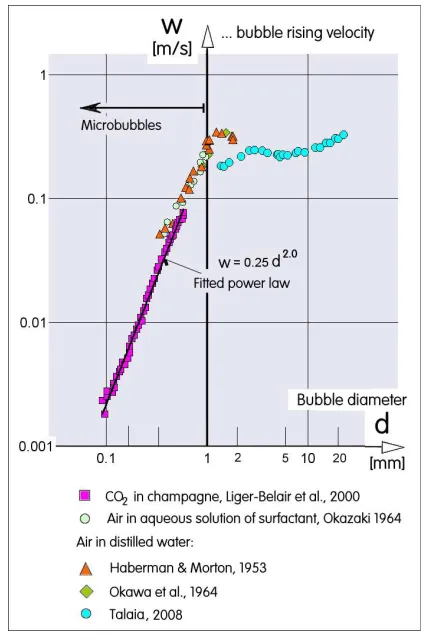
Figure 7
Collection of experimental data about rising velocity of bubbles and microbubbles in the liquid. Quite important fact is the change in the behaviour at the microbubbles’ upper size limit d = 1 mm - though it was originally chosen only for convenience and simplicity.not posses a strictly spherical shape. Even if they are stationary, their geometry is deformed by the hydrostatic pressure difference between the bubble top and bottom. In microbubbles the internal pressure is so much higher that a deviation from sphericity is negligible.
Even more shape differences between the practically always spherical microbubbles and larger bubbles are apparent in studies of the microbubble ascent in the liquid towards the surface above. Large bubbles tend to be deformed by hydrodynamic forces. Also the character of the ascent velocity w [m/s] dependence on the bubble diameter d is different in the two cases. It is remarkable visible in Fig. 7, which presents collected experimental data of various researchers. Microbubbles rise at a velocity practically proportional to the square of their diameter. Ascent velocity of larger bubbles varies in a complex way, with the velocity being roughly the same Other differences in behaviour are associated with the propagation character of various processes, like the heat transfer schematically represented in Fig. 8. In larger bubbles the propagation inwards takes place in the form of boundary layer with progressively growing thickness – while the microbubbles, being very small, became affected practically simultaneously throughout their full internal space.
Based on a similar factor, demonstration by Al-Yaqoobi, Hogg, and Zimmerman [7] have found another remarkable difference. They have shown potentially very important qualitative properties of microbubbles in separating ethanol-water mixture — or even azeotropic mixtures not separable by traditional distillation process. In the industrially important ethanol-water case, the traditional distillation approach requires large amounts of heating energy to get the liquid to its boiling point. The concept of isothermal microbubble distillation is to heat the gas phase rather than the liquid phase to achieve separation. The advantage of the microbubble distillation was in achieving vapour concentration higher than that what can be obtained under the equilibrium conditions.
Figure 8 What appears to be outwardly another qualitatively different property of microbubbles is the simple consequence of their diameter dVP smaller than the distance δ of diffusive transport in the gas.
4 Applications review
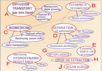
review illustration Fig. 9. The application cases are there grouped into families with their names in red ellipses. Individual uses belonging to a family are named inside blue ellipses.
Admittedly, some of the applications listed there are just first ideas, not having yet progressed to an industrial scale. As a matter of fact, some of the listed cases (typically among them is the idea of changing ocean albedo) would require so huge financial investments that they are not likely to be pursued in foreseeable future. Fig. 9 takes this into account by arranging the applications in the degree of their realisation possibilities. Those already used and developed, like the case A (note the increased shade of the background), are drawn near
the left top corner – while those at present less likely to employ industrially are at right in the bottom pf the image.
What should be also noted in this illustration are the connecting lines drawn between some application families. They put together those cases that, although belonging to different use areas, are based on physically related physical principles. A typical example are the microbubbles use to separate components from a mixture. There are such separation processes in which the obtained substances are discarded as unwanted – yet similar separation processes, on the other hand, are cases where the extracted substance is the very object of the whole application effort.
Figure 9 Survey of currently investigated microbubble applications that were made possible (and in some cases economically feasible) by oscillation generated by fluidics. Currently the development is particularly rapid in bioreactors and in medicine.
5 Enhanced transport phenomena
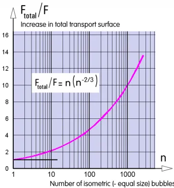
The family A in Fig. 9 was the initial reason behind the renewed (or increased) interest in microbubbles. The idea of increasing the total contact surface by division of the given total volume into many small-size objects is obvious and thus the first generating of microbubbles for this purpose, Figs. 10 and11, was immediately accepted without a need for deeper investigation. Recent interest is primarily in quantifying the effect microbubbles have on the overall gas transport efficiency in the liquid. A paper on this subject – for the particular case of O2 transport to water in which it dissolves – is e.g. ref. [8]. The dissolved oxygen in water is, in particular, needed to support existence of aerobic bacteria, presence of which is necessary in various biochemical processes. Of recent interest are also the interphase transport processes in microbubble-sparged airlift reactors, discussed in [9]. Fluidic oscillators can generate in the airlift loop a microbubble cloud. Mass transfer through such cloudsFigure 11 Dependence on the number n of the small bubbles from Fig. 10 of the transport surface F increase (assuming the same size and perfectly spherical shapes).
in the case of carbon dioxide diffused into water was investigated, e.g., in [10]. The efficient delivery of CO2 to simple, unicellular plants living in water is a subject of extremely high contemporary importance. Green plants, including the simple algae, possess the extraordinary capability of generate by photosynthesis various hydrocarbon compounds needing only water, light, and CO2 from water. It is no problem for contemporary chemistry to convert the resultant product into the liquid fuel for powering e.g. automobiles. The advantage of simple organisms used for this purpose is their extremely fast reproduction cycle – providing they obtain suitable conditions. This idea is not at all surprising. The photosynthesis is, after all, the same process by which were generated simple plankton organisms, from which the crude oil was made ~ 300 million years ago. Imitating the same procedure at an industrial scale can solve the grave problems of geopolitics – the unbalance between the countries possessing the crude oil sources and those that are the largest consumers. A recent comprehensive review of the tasks and problems aiming at the particular case of bioethanol is available in [11] and more general recent progress in developing oil from algae is discussed in [12]. Pilot scale studies and specifically a design of an airlift bioreactor for the algae growing purpose with fluidic oscillator induced microbubbles are described in detail in. [13].
6 Microbubbles used for cleaning
Important increase in effectiveness over earlier techniques is offered by microbubbles also in the applications summarised in Fig. 9 as the case B. It is the cleaning and waste removal as well as processing. Typical wastewater processing plant [14] actually entrusts the cleaning process to aerobic bacteria (anaerobic ones can perform the procedure as well, but slowly and with roughly 10-times lower efficiency). The basic problem of the aerobic organisms is generalabsence in household wastes of oxygen they need – and without which they die. This has been recognised long time ago and practically all present-day plants include some form of aeration, which consumes some 70 % of the typical plant running costs. Unfortunately, present day facilities usually employ for aeration some forms of paddlewheels, with efficiency which is very poor An early development of microbubble aerator for higher-efficiency waste water treatment using aerobic activated sludge was described by Terasaka et al. in [15].
Figure 12 The removal of dirt - or, generally, different components - involves complicated action of ionts on the bubble surface. Nevertheless at least some of the intensive removal effect by microbubbles is explained by their small size and geometrically easier attachment to the complex surfaces.
Another process which microbubbles take part in cleaning tasks is using their strong clinging to contaminants like oil or grease, cf. Fig. 12. The fact of substantial importance is they make possible an removal of dirt from processed water environmentally friendly. The process does not work with any chemical detergents. This was discussed in [16]. As an example, in [17] is quantitatively evaluated the use of microbubbles to de-contamination of manufactured silicon wafers. Their yield losses over 50% are so far caused by micro-contamination, difficult to remove by present methods. It is demonstrated in [17] to be easily and environment friendly removable by microbubbles. In fact, microbubbles were demonstrated by Tsuge et al., [18] even to perform disinfection by removal of pathogens. The mechanism presented in Fig. 12 is nowadays offered on a commercial basis to cleaning skin and hairs of home pets, according to Fig. 13. Human use of this disinfection is now still in a stage of administrative approval tests – suggesting, nevertheless, the potential use in biomedical
applications. Schematically represented in Fig. 14 is another essentially cleaning type application. It is a use in a technologically quite distant area: extracting crude oil (or natural gas) from what has been so far considered to be „aged“ and no more useful wells — especially those in which the extracted fluid is firmly held in tiny pores and fissures in the rocks. Microbubbles generated in the downhole oscillator can enter the crevices and displace the exploitable fluids that would otherwise remain there as not mineable. In addition, the existence of tiny microbubbles, only extremely slowly moving relative to the surrounding crude oil, form together with it a mixture
Figure 14 Although belonging to a very much different application family – the proposed crude oil and gas extraction should use, as underlying principle, the separation and cleaning effect by creeping into tiny cleavages and displacing from there the extracted fluid.
exhibiting very small overall density. This is reflected in the correspondingly very low hydrostatic pressure that has to be overcome in the extraction process in the production well.
7 Biomedical uses
Microbubbles found application Cin medicine very early – and in a wide spectrum of uses. Again, some of uses belong to the diffusion and/or reaction controlled transport phenomena – for example ref. [19] investigated transport and reaction-controlled dissolution of oxygen microbubbles in flowing blood.
The most successful early application of microbubbles present in human body fluids was due to their ability to scatter and reflect ultrasound – enhancing substantially this diagnostic method [20]. Besides the pre-clinical ultrasound imaging, There are pre-clinical application, like the assessment of myocardial perfusion reported in [21]. Microbubbles can also convert energy of the ultrasonic vibration into a local thermal therapeutic effect [22]. Streaming effect on microbubbles in ultrasonic field can destroy cells [23] and can cause permeabilisation of membranes for drugs [24] in particular the anti-cancer ones [25, 26]. Microbubbles of suitable composition possess ability to target specific cellular markers of disease and deliver localised chemotherapy. Recently demonstrated was capability to
switch on mechanisms of gene therapy and enhance lesion ablation through cavitation. Microbubbles as drug carriers are traced inside the body using a low-intensity ultrasound and burst at the target site by applied high-intensity ultrasound. As a particular success is considered the recently demonstrated drug delivery to the brain by focused ultrasound and microbubble-mediated disruption of blood-brain barrier [27, 28]. Of large importance are the recent uses for tumor ablation, sonothrombolysis, and stroke therapy. Microbubbles were also demonstrated in use for measuring absolute blood pressure [29]. Systems with microbubbles have been developed for screening of peptides specific to colon cancer cells and also for capturing circulating tumor cells to provide early cancer diagnosis [30].
8 Separation techniques
This family D of microbubble applications includes mainly the techniques already mentioned above as belonging to the respective application families, as shown in Figs. 12, 13, and 14. There are, however, uses in areas that are seemingly quite unrelated. One of them is mineral engineering [31]. The clinging of microbubbles to small particles produced by grinding is used for separation by flotation technique. This enhanced separation by flotation, together with advances in grinding, allow now economic exploitation of deposits that a decade ago would be described as too low-grade and therefore uninteresting.
Flotation on one hand – and its opposite, gravity sedimentation — are currently an object of intensive research associated with the farming of algae discussed above in sect. 5. as of immense interest for generating renewable petrol. While harvesting of some heavier algae is more efficient by use of sedimentation, other algae taxonomic group have their settling velocity in water so low that microbubble-facilitated flotation is a better alternative. Ref. [32] presents an example of microflotation through microbubble clouds. Another separation technique that may benefit from use of algae is flocculation. Also in this case the interest concentrates on identification of the least expensive harvesting of algae. In [33] is discussed separation from urban landscape water using a high density microbubble layer enhanced by micro-flocculation.
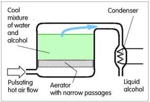
Figure 16 Schematic temperature dependence on height of rising initially hot air microbubble in the distillation process. Water condenses and leaves the bubble before reaching the surface. The advantage is no heating of most of the liquid, saving the energy.
Energetically very important distillation by microbubbles may be explained by means of Figs. 15 and 16. The fluidic pulsation of the hot air fed into the aerator generates hot microbubbles. They become soon saturated by vapours of water (boiling at Tw = 100
o C) and ethyl alcohol (boiling at Te =78.36 oC) from the surrounding liquid mixture. Soon the microbubbles, exchanging heat with the liquid, cool to Tw and the condensing water leaves the bubble. Remaining air and alcohol vapour microbubble reaches the liquid surface before its temperature decreases below Te
.
It bursts there and frees the alcohol, which is then converted into the liquid in the condenser, Fig. 15.Finally, eat another separation technique of high and increasing importance is producing potable water from sea water by desalination. The highest perspective is seen for reverse osmosis desalination by semi-permeable membranes [34] with membrane efficiency improvement by microbubbles.
9 Food production
Microbubbles also find applications in producing food, E. They can bring two advantages over the current state of art. One of them is significant improvement of sensory qualities of dietary products, especially the smoothness that is demonstrably higher. US Patent [35] also covers potential of microbubbles as fat replacer The low-fat food contains aqueous phase, oil droplets, and protein coated air microbubbles. The other way towards improvements in food industry is extending the shelf-life of products of foamy character – such as whipped cream, salad dressings, sorbets, and mousses. Some of these products, typically ice-creams, have to be made by a specialised machinery on the spot to retain their immediately recognisable freshness – which is rather expensive. It is a considerable advantage that a foam of microbubbles was demonstrated to remain stable for up to a year. Gas-to-liquid mass transfer being the rate-limiting step in aerobic fermentations, improving the efficiency by using microbubbles is obvious. Also of interest for food
industry is water evaporation ability of microbubbles [36] without the heat reaching the dried product.
10 Reducing the friction drag
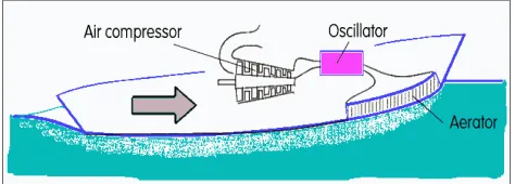
Decreasing the resistance to motion of a body in water by blowing air bubbles on the water contact surfaces F – such as under the ship or boat bottom - has been a quite old idea, Fig. 17. It was intuitively felt a way to significant improvement of transportation efficiency – although it should not be forgotten that it can decrease only the friction resistance and not the other source of the total drag – the generation of waves on water surface. Tests of the idea, actually already with microbubbles, were performed and described in [37] as long time ago as in 1973, i.e. before the era microbubbles generated fluidically. A quite large reduction in the frictional resistance component under laboratory conditions (no wave drag) was demonstrated.
Figure 17 Schematic principle of increasing the speed of a fast boat by injecting microbubbles into water at the bow.
Discontinuation of the progress was due to the inefficient method used to microbubbles generation. The gas was actually not air but hydrogen, generated by water electrolysis. The generation unit required and spent more energy than was saved on the propulsion side. The same problem of inefficient microbubble generation at the quite large scale, required to obtain reasonable Reynolds numbers, plagued also other later attempts, including those that were able to show remarkable friction drag reductions up to 80% — i.e. decrease to mere one fifth of original value [38, 39] – of course with large gas or air flow rates. Ship model tests with microbubbles have been already made at size scale near to that of practical use — there are reports of practical tests of Indonesian Navy fast patrol boat [40].
For process engineers may be important the corresponding decrease by microbubbles of fluid flow frictions in pipes and tubes [41, 42].
11 Applications at microfluidic scale
Many of the currently developed techniques of using microbubbles aim at a very small, microfluidics scale applications. A use was found in gene manipulation [46], biosensors [47], mixing of reactants for chemical microreactors [48] or sorting small object transported in a fluid [49].G, where ordered microbubble configurations, e.g. microbubble linear arrays, can create tuneable optical components [50, 51] for control of laser light.
12 Extracting crude oil
One particular aspect of this application H was already discussed in Sect. 6 in association with Fig. 14. It is the capability of microbubbles to displace the mined fluids. Another aspect — also in association with the so called “aged” oil wells — should be also mentioned. The large depths from which oil is obtained necessarily generate correspondingly large hydrostatic pressure that must be overcome. As the oil is removed, the naturally present pressure inevitably decreases until at a certain stage the extraction ceases to be useful — even though down there still remains a considerable amount of the oil. The remedy may be bringing to the bottom of the hole compressed air. The mixture of oil and air has substantially lower density and the oil flow may continue — as long, however, as the air remains in the mixture. On the very long travel upwards standard air bubbles coalesce. This finally leads to the situation shown schematically at the left-hand side of Fig. 18. The air separated from the mixture rises through the hole centre while at the walls forms an annular layer of the oil flowing down and not reaching the required upwards location.
Replacing the standard large bubbles with microbubbles, is a reasonable solution. With their slower motion in the oil - and also the very long vertical path before their coalescence reaches any dangerous level - makes extraction of the oil (at right in Fig. 18) again profitable.
Figure 18 Blowing air downhole does not secure getting the oil to the surface. Standard large bubble coalesce (left) and the result is blowing up the released air alone while the oil flows down on riser pipe walls. With microbubbles (right) is blown up a mixture causing smaller hydrostatic pressure.
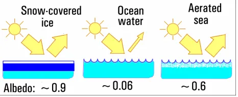
13 Increasing albedo of oceans
Albedo is the term used to characterise the “whiteness” of planetary surface exposed to sun light. The higher is the albedo value, the larger is the amount of thermal power that is reflected from the surface (and therefore the smaller is the remaining amount that is absorbed). Albedo of ice - especially when covered, as usual, with fresh snow, Fig. 19 - is very much near the top of the scale from 0.0 to 1.0. On the contrary, albedo of deep ocean is, near the very bottom of this scale. In the glaciers and ice melting under the present condition of global warming there is an interesting negative feedback phenomenon. The more ice is melt in the Arctic (and the lower is the decreasing albedo of the water surface there), the more thermal power is absorbed and the faster is the ice removal.
In principle at least, there is a possibility discussed in [51] how to prevent this feedback from closing itself: generating microbubbles on the ocean surface can replace the missing ice albedo.
Figure 19 The global warming may be suppressed by sunlight reflecting microbubbles blown into an ocean surface layer to increase their albedo.
Conclusions
Fluidics, the technique of generating and handling fluid flows – preferably without an action of mechanical components – came recently with a so far not widely known possibility how to generate very small, sub-millimetre sized gas bubbles in liquids. components. Perhaps even less that the microbubble generation principle has been so far known the reason why it should be useful and profitable to generate them. Present paper contains a survey and classification of the microbubble applications that may provide an inspiration for further research in this area.
Acknowledgements
Author obtained support from GAR - Grant Agency of the Czech Republic, by research grant Nr. 13-23046S. There was also institutional support RVO:61388998.
References
1. Prevenslik T., Proc. of Conf. ‘Topical Problems of Fluid Mechnics’, p. 113, Prague 2014
2. J. Rodríguez-Rodríguez et al., Annual Review of Fluid Mechanics, 47, 405,(2015)
3. V. Tesa V., C.-H. Hung, W.B.J. Zimmerman, Sensors and Actuators A, 125, 159, (2006)
4.. W. B. J. Zimmerman, V. Tesa, European Patent.
5. Z. Trávníek, Engineering Mechanics13, 67, (2006)
6. V. Tesa, Chemical Engineering Science, 116, 843, (2014)
7. A. Al-Yaqoobi A., D. Hogg, W. B. Zimmerman,
International Journal of Chemical Engineering, ID 5210865, 2016
8. T. Andinet, I. Kim, J.-Y. Lee,Desalination and Water Treatment, in Press (2016)
9. A.M. Al Taweel, A.O. Idhbeaa, A. Ghanem A., Chemical Engineering Science 100 474 (2013)
10. M.K.H. Al-Mashhadani, H.C.H. Bandalusena, W.B. Zimmerman, Industrial and Engineering Chemistry Research51 1864 (2012)
11. A. R. Sirajunnisa, D. Surendhiran, Renewable and Suistainable Energy Reviwes 66 248 (2016)
12. K. Kumar et al., Renewable and Sustainable Energy Reviews65 235 (2016)
13. W. B. Zimmerman et al., Appl. Energy88 335 (2011)
14 Zhang L. et al., Water Science and Technology 74 138 (2016)
15 K. Terasaka et al., Chemical Engineering Science 66 3172 (2011)
16. K. Wataneabe et al.,: Proc. of FLUCOME 2013, 12th Intern. Conf., Nara, Japan, November 2013
17. Xi, X., PhD Thesis, Mechanical Engineering Department, Imperial College London, 2012
18 Tsuge H., et al., Kagaku Kogaku Ronbunshu 35 548 (2009)
19. M. Fischer, I. Zinovik, D. Poulikakos, International Journal of Heat and Mass Transfer 52 5013 (2009)
20. P. Kogan, R.C. Gessner, P.A. Dayton, Bubble Sci. Eng. Technol, 2 3 }2010)
21. L. Rotaru, T. Nanea, Journ. Med. Life 8 471(2015)
22. T. Kanagawa, Proc. of FLUCOME 2013, 12th Intern. Conf., Nara, Japan
23. K. Kooiman et al.: Journal of Controlled Release 154, 35, (2011)
24. J. S. Oh J. S. et al., Computers in Biology and Medicine
44 37 (2014)
25 Y. Watanabe et.al., Cancer Science 99 2525 (2008)
26. S.-T. Ren et al., Physics of Fluids, 27 356 (1984)
27. W.M. Pardridge, NeuroRx. 2 3 (2005)
28. T. Q. Nan, PhD Thesis, Univ of Toronto, Canada (2005)
29. C. Tremblay-Darveau et al., Ultrasound in Medicine and Biology40 775 (2014)
30. Y.-H. Hsiao, Scientific Reports, 6 32454 (2016)
31. E. Waters, K. Hadler, J.J. Cilliers, Minerals Engineering
21 918 (2008)
32 J. Hanotu, H.C.H. Bandulasena, W.B. Zimmerman,
Biotechnology and Bioengineering, DOI
10.1002/bit.24449
33. S. Chen et al., Water Sci. Technol.,70 811 (2014)
34. H. Hasegawa, S. Otsu, Transactions of the Japan Society of Mechanic Engineers, Ser. B 77 2049 (2011)
35. I.T. Norton, P.W.Cox, Tchuenbou-Magaia F. L., US Pat. US8647696 B2, filed 2008
36. W. B. Zimmerman, M. K. H. Al-Mashhadani, H.C.H Bandulasena, Chemical Engineering Science101 865 (2013)
37. M. E. McCormick, R. Bhattacharyya, Naval Engineeris Journal 85 11 (1973)
38. V.G. Bogdevich et al., Proc of2nd Second Internat. Conf. on Drag Reduction BHRA, Cambridge, (1977)
39. N. K. Madavan et al., Phys. of Fluids 27 356 (1984).
40. Yanuar et al., Mar. Sci. Technol 17 301 (2012)
41 O. Watababe, A. Masuko, Y. Shirose, J. Soc. Naval Archit.183 53 (1998)
42 Y. Moriguchi, H. Kato, Journal of Marine Science and Technology7 79 2002
43 M. J. Pang, J. J. Wei, B. Yu, Ocean Engineering81 58 (2014)
44 M.M. Shams, M. Dong, N. Mahinpey, Chemical Engineering Science 112 72 (2014)
45 R.R. Sun et al., Journal of Controlled Release182 111 (2014)
46 L. A. Kuznetsova, W. T. Coakley, Biosensors and Bioelectronics, 22 1567 (2007)
47 J. H. Lee et al., Sensors and Actuators A 182 153 2012
48 C. Wang, Biomicrofluidics6 012801 (2012)
49 M. Hashimoto et al., Small2 (2006)
50 A. Allouch, Microfluidics and Nanofluidics1 (2004)
![Figure 6 Microbubble generator principle. This drawing was originally prepared for the Patent Application [4]](https://thumb-us.123doks.com/thumbv2/123dok_us/8142902.1357352/3.595.70.271.65.196/figure-microbubble-generator-principle-drawing-originally-prepared-application.webp)