Bluetooth Hotspot: Extending the Communication
Range between Bluetooth Devices
Pooja Sharma
B.S. Anangpuria Institute of Technology and Management Faridabad, Haryana
Deepak Tyagi
St. Anne Mary Education Society , Delhi
Pawan Bhadana
B.S. Anangpuria Institute of Technology and Management Faridabad, Haryana
Abstract- Bluetooth is a wireless radio specification designed to replace the cables as the medium for data and voices signals between electronic devices. Bluetooth’s design sets a high priority on small size, low power consumption and low costs. The Bluetooth specification seeks to simplify communication between electronic devices by automating the connection process. In this paper we explain Bluetooth protocol stack and its different layers, then moving on to how Bluetooth networks are formed and devices are located. The proposed idea in this paper is to develop Bluetooth hotspot and examine two different implementation approaches. BlueSpot, the software components of the proposed Bluetooth hotspot are introduced, as well as the connection framework between these components and other hotspots.
1. INTRODUCTION
Ad hoc networks today are based primarily on Bluetooth technology. Bluetooth is an open standard for short-range digital radio. It is touted as a cost, power, and low-profile technology that provide a mechanism for creating small wireless networks on an ad hoc basis. Bluetooth is considered a wireless PAN technology that offers fast and reliable transmission for both voice and data. Untethered Bluetooth devices will eliminate the need for cables and provide a bridge to existing networks.
As with all ad hoc networks, Bluetooth network topologies are established on a temporary and random basis. A distinguishing feature of Bluetooth networks is the master-slave relationship maintained between the network devices. Up to eight Bluetooth devices may be networked together in a master-slave relationship, called a “piconet.” In a piconet, one device is designated as the master of the network with up to seven slaves connected directly to that network. The master device controls and sets up the network (including defining the network’s hopping scheme). Devices in a Bluetooth piconet operate on the same channel and follow the same frequency hopping sequence. Although only one device may perform as the master for each network, a slave in one network can act as the master for other networks, thus creating a chain of networks. This series of piconets, often referred to as scatter-nets, allows several devices to be internetworked
over an extended distance. This relationship also allows for a dynamic topology that may change during any given session: as a device moves toward or away from the master device in the network, the topology and therefore the relationships of the devices in the immediate network change.
Mobile routers in a Bluetooth network control the changing network topologies of these networks. The routers also control the flow of data between devices that are capable of supporting a direct link to each other. As devices move about in a random fashion, these networks must be reconfigured on the fly to handle the dynamic topology. The routing protocols it employs allow Bluetooth to establish and maintain these shifting networks. Bluetooth uses a combination of packet-switching technology and circuit-packet-switching technology. The advantage of using packet switching in Bluetooth is that it allows devices to route multiple packets of information by the same data path. Since this method does not consume all the resources on a data path, it becomes easier for remote devices to maintain data flow throughout a scatter-net.
2. BLUETOOTH PROTOCOL STACK
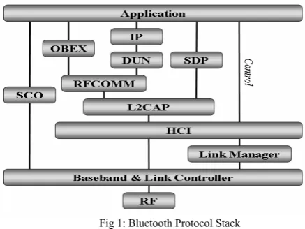
The protocol stack makes up the core portion of the Bluetooth implementation. This stack enables devices to locate each other and establish a connection as shown in Figure1. Through this connection, devices can exchange data and interact with one another through various applications.
2.1 Core Lower Layers
2.1.1 Radio
narrowband carrier that changes frequencies in a pattern known to both the transmitter and the receiver. Data is broken up into very small packets and transmitted usually one packet per frequency jump or slot.
2.1.2 Baseband / Link Controller
Above the radio layer are the Baseband Layer and Link Controller Layer [2]. These two layers are not clearly separated by the specification. The baseband layer’s role is to properly format data for transmission to and from the radio module and perform basic error control. It also performs basic piconet management such as signal transmission timing and frequency hop selection. The link controller’s role is to establish and maintain the links that are set up by the link manager.
Fig 1: Bluetooth Protocol Stack
2.1.3 Link Manager
The Link Manager [2] translates commands sent by the Host Controller Interface (HCI) layer and acts as a contact between the application and the link controller. Once two devices have set up a link with each other, the link managers on the devices can communicate with each other, probing for each other’s communication characteristics using the Link Manager Protocol (LMP). It is responsible for establishing and configuring links.
2.2 Host Controller Interface (HCI)
Sitting between the lower layers and the upper layers is the HCI layer [2]. The HCI is defined by the Bluetooth specification as a standard to support Bluetooth systems that are implemented across two separate devices.
2.3 Core Upper Layers
2.3.1 Logical Link Control and Adaptation Protocol (L2CAP)
The Logical Link Control and Adaptation Protocol (L2CAP) [2] acts as the middle manager between applications and the Bluetooth Link Controller. Once a connection has been established (by the Link Manager) it handles the actual data communication between devices from the higher layers. Its main functions are [1]:
Establishing connections across links created by the link manager, or requesting links be established by the link manager.
Protocol multiplexing between different higher layers allowing multiple different applications to use a single link between Bluetooth devices simultaneously.
Segmentation and reassembly of packets to and from the lower layers.
Quality of Service.
Group Management.
2.3.2 Service Discovery Protocol (SDP)
The Service Discovery Protocol (SDP) [2] as defined by the Bluetooth specification is a very important layer in the Bluetooth protocol stack as it allows Bluetooth devices to inquire what services Bluetooth devices offer or locate a device with a particular service. Services are defined by different profiles and represent a feature that is usable by a remote Bluetooth device. SDP consists of servers and clients components, where the requesting devices are a client and the requested device the server. A single Bluetooth device can perform both roles of a SDP-server and -client.
2.4 Non-Core Upper Layers
2.4.1 RFCOMM
RFCOMM [3] is based on the GSM 07.10 Multiplexing Protocol standard [8], with a few minor differences. It provides a RS-232 serial port emulation which can be used by legacy applications. It also is used by several other Bluetooth profiles for their data transfer.
2.4.2 OBEX
OBEX (“OBject EXchange”) [2] [5]is a communication protocol that facilitates the exchange of binary objects between devices, and uses RFCOMM. It is mainly used for the exchange of business cards, calendar appointments and files.
2.4.3 Bluetooth Network Encapsulation Protocol (BNEP)
The Bluetooth Network Encapsulation Protocol (BNEP) sits on top of L2CAP and allows standard network protocols such as TCP, IPv4 and IPv6 to be transported across Bluetooth links. BNEP provides this encapsulation by replacing the Ethernet header, with a BNEP header and sends this header and the data across the L2CAP layer.
2.5 Audio
Audio information between Bluetooth devices such as headset to mobile phones are carried via Synchronous Connection-Oriented (SCO) channels. These channels bypass most of the Bluetooth protocol stack and connect via a direct PCM connection to the baseband layer. This direct connection avoids problems with flow-control across the HCI Layer. [1]
2.5 Finding A Device
formation of piconets. These states are shown in Figure 2. For device discovery, the three states are inquiry, inquiry scan and inquiry response.
2.5.1 Inquiry state
The inquiry state is entered when a device attempts to discover all other devices within range. In this state, the searching device repeatedly transmits an inquiry message on a set of different frequencies in a hopping sequence shown in figure 3, whilst it listens for responses.
Figure 2: State Diagram of Link Controller From [1]
When another device responds its information is added to an internal list of devices found, which is used if a connection is requested later. The inquiry state is continued until the Baseband has received enough responses, when a timeout has been reached or when the host issues a command to cancel the inquiry. [4]
Fig3: Sequence chart of Inquiry Process From [1]
2.5.2 Inquiry Scan state
For a Bluetooth device to be discoverable, it has to answer inquiry messages from other devices. This is done by entering an optional inquiry scan state. A device which is discoverable
does this periodically (at least every 2.56 seconds) and listens for an extended time compared to the inquiry state. [4] If a device does not want to be located it can be set to be non- discoverable and therefore will not enter the inquiry scan state.
2.5.3 Inquiry Response state
When a device receives a valid inquiry message it will then enter the inquire response state and respond with a frequency hopping synchronisation (FHS) packet. A FHS packet is a special control packet that contains the Bluetooth device’s hardware address (called the BD_ADDR) and the Bluetooth clock of the responding device. [4] The Bluetooth clock is a 28-bit internal clock that ticks every 312.5 ms and is used for triggering critical events such as timing the hopping sequence [2]. The BD_ADDR will be used later by the searching device to address the discovered device. [4]
3. CONNECTION ESTABLISHMENT
The paging procedure discussed below is used to establish a new connection between two devices. Only the Bluetooth address is required to setup a connection, but if the clock of the other device is known from an inquiry process or a previous connection, the setup procedure can be completed much quicker. The device that initiates the connection is designated the master of the connection. There are four states that devices go through to establish a connection; Page, Master response, Page Scan and Slave response, which are shown in Figure 2 in the previous section.
3.1 Page State
This state is used by a connecting device, known as the master, to find and connect to another device, known as the Slave. The master attempts to match the slave’s scan hopping sequence by repeatedly transmitting a paging message to the slave in different hop channels. From the slave’s BD_ADDR and clock, the master can work out the slave’s hop sequence, but will not know at which point in the sequence the slave is as at that time. To work out where in the sequence the slave is, the master uses an estimate of the clock, which it can base on a previous inquiry or connection. Given that clocks may drift, it is unlikely that the estimate will be entirely accurate so the master transmits the paging messages at twice the usual frequency to compensate [4].
3.2 Page Scan State
As in the Inquiry Scan state, a device will periodically enter a Page Scan state where it will listen for page messages from other devices. It does this by following a particular hopping sequence and listening at each of the different frequencies for 1.28s [4].
3.3 Slave Response sub-state
On receipt of a page message from the master, the slave will then enter the Slave Response sub-state as shown in figure 4. It will then transmit a slave page response message to Standby
Inquiry Inquiry
Scan
Inquiry Response
Master Response
Page Scan
Slave Response
Connection
acknowledge the page message. This response is transmitted 625 μs after the page was first received and on the same frequency that it was received on. It will then wait for the master to send a FHS packet. When the FHS packet is received, the slave device acknowledges it and will then adjust its hopping sequence and clock to match those of the master's, as given in the FHS packet. The slave will then be synchronised and connected to the master. [4]
Fig4: Sequence chart of Paging Process From [1]
3.4 Master Response sub-state
When the master receives the acknowledgement of the page from the slave device it enters the Master Response sub-state and will reply with a FHS packet which contains its BD_ADDR and clock. The master will then wait for the second slave response message. If it does not receive one, it will send another FHS with an updated clock, and keep doing so in each time slot of the hopping sequence until the slave responds or a timeout is exceeded. If an acknowledgement is received, the master will revert to using its own hopping sequence and enter the connection state. The first packet the master will send to the slave is a POLL packet. The slave may respond with any type of packet. If the slave does not receive a POLL packet, or the master a reply packet the master and slave will return to the Page and Page Scan states, respectively. [4]
4. PROPOSED BLUETOOTH HOTSPOT
In this section we proposer a Bluetooth hotspot and examine two different implementation approaches.
4.1BlueSpot
BlueSpot, the software components of the proposed Bluetooth hotspot are introduced, as well as the connection framework between these components and other hotspots. As we know Bluetooth devices that are out of radio range to communicate with each other we envision setting up a collection of devices that would be connected together by an IP network as shown in Figure 5 and would act as what has been called Bluetooth Hotspots. The reason for the name is that it is similar in
concept to Wi-Fi hotspots where mobile devices can connect to each other through an access point connected to a wired network.
These Bluetooth Hotspots would allow Bluetooth devices that are distant from each other but within range of a hotspot to be able to communicate with each other via the hotspots. For example, a person who is in a boardroom meeting is able to access information on his/her computer back in the office.
Fig5: Bluetooth Hotspot
Even though the distance between the boardroom and the office is greater than the maximum transmission range of Bluetooth, both locations have Bluetooth Hotspots installed that connect these two locations and enabling the PDA to communicate with the computer as if he/she were back in their office.
4.2 Different Approaches
The functionality of extending the reach of Bluetooth communication can be implemented at different layers in the Bluetooth protocol stack, each with its individual tradeoffs in efficiency, scope of service support and ease of implementation. These could be broken down into two primary implementation approaches:
hotspots masquerade as other remote Bluetooth devices, and
hotspots offer or otherwise proxy the services offered by other devices
4.2.1Masquerading
From a user’s perspective the easiest means of using a Bluetooth hotspot would be to make it seamless and transparent while accessing the remote device. This requires designing a system where each hotspot is able to masquerade as other Bluetooth devices and therefore able to advertise itself as a device that is located at other hotspots. This is shown in Figure 6 where Bluetooth Device A is communicating with Bluetooth Device B via the hotspots. Each Bluetooth device thinks that it is communicating directly with each other but in fact are communicating with the respective hotspot which is masquerading as the distant device. This would allow for very easy access to, and use of, the hotspots.
Fig6: Using masquerading to create communications Bluetooth Device A Bluetooth Device B
Hotspot X Hotspot Y
The main obstacle foreseen for this approach is that a Bluetooth network does not use a single channel for all communications like a LANs physical cable or a Wi-Fi channel, but rather the communication is spread across 79 channels that are switched between quickly to combat interference. This makes it difficult for a Hotspot to “listen on” to all other communications.
4.2.2 Using Service Proxying
The second method was to examine Bluetooth’s SDP and the feasibility of using SDP to provide facilities to discover remote devices and make possible the setting up of communication links between devices.
Fig7: Using Service Discovery to create communications
The scenario that was envisioned is shown in Figure 7, where a user (Device A) within the range of a hotspot (Hotspot X) is able to query that hotspot for all the services that it offers. The hotspot will then return a list (“Services Available”) of what other devices (Device B) are within range of other distant hotspots (Hotspot Y) and what services they can offer to allow for communication with a distant device. If the user then, for example, chooses to “Sync with Device B,” a communication channel would then be set up between Device A and Device B by the hotspots that will transparently transport the communication over the IP network. Applications on either end will then seamlessly communicate with one another, unaware that the devices are not within radio range.
4.3 Bluetooth Hotspot
The Bluetooth hotspot is made up of various components. The hardware consists of a processing unit, a device to communicate over Bluetooth and a device to communicate to an IP network. The software consists of the Bluetooth protocol stack and a collection of custom written applications, which have been called BlueSpot, shown in Figure 8. The software is made up of three separate but interlinked components:
Management: Manages the other software components that make up the hotspot as well as detects when Bluetooth devices come within range and leave.
Service Database: Collects, stores and advertises services that are detected by all the Bluetooth hotspots within a network.
Transport: This makes the connection between hotspot and Bluetooth devices and transports the Bluetooth data across the IP network.
Fig8: Components of the Bluetooth Hotspot
4.3.1 Management Component
The main role of the Management Component is to supervise the different applications that make up the Service Database and Transport Components, such as starting and stopping the applications when needed. One of the important tasks it would need to perform is to detect when Bluetooth devices come within and go out of range of the hotspot. It does this by periodically scanning for local Bluetooth devices that have entered range, as well as detecting when a previously detected device is no longer communicating. When a new Bluetooth device is detected it will be queried to find out its basic information such as its name and type of device. It will then inform the Service Database Component that there is a new device.
4.3.2 Service Database Component
The Service Database Component locates and advertises services from all devices within reach of the hotspots, and uses this information to manage the creation of the different connections using the transport component as needed. When it is notified of a new Bluetooth device it will acquire a list of all the services that that device is advertising via its SDP server. These services are then checked to see if they have transport applications available. The services that can be transported are then added to an internal database and all the other remote databases are notified about the newly detected service. The local and remote databases will then start the respective transport applications. Once the transport applications are running the remote service database will add the service to its local SDP server.
4.3.3 Transport Component
As their name implies the transport components in fact “transport” the Bluetooth communications between two Bluetooth devices via the Bluetooth hotspots over an IP network. In essence the transport component pairs are a proxy server in that they allow clients (Bluetooth devices) to make indirect (via IP network) network connections to other network services (i.e. services available on remote Bluetooth devices).
4.4 Connection Framework
below. The two jobs that a Bluetooth hotspot performs are the advertising of services from remote devices and the facilitating of communication between two devices.
4.4.1 Advertising a Service
1. The process of advertising a service follows this sequence of steps shown in Figure 9 Bluetooth Hotspot X detects Bluetooth Device A
2. The Management Component informs the local Service Database Component (SDC) of the new device within range 3. The SDC queries the SDP Server on the Bluetooth device and finds out what services it is able to facilitate.
4. The SDC starts the Transport Components for the services above.
Fig9: Communication Framework: Advertising a service
5. The SDC informs all other SDCs that have previously connected to it about the new services it has located
6. The remote Service Database starts its side of the Transport Components
7. The remote SDC adds the new services to the local SDP Server with the information needed to connect to the local Transport Components
4.4.2 Using a Proxyed Service
The process of using a proxyed service follows this sequence of steps shown in Figure10.
Fig10: Connection Framework: Using a Proxyed Service
1. A Bluetooth Device B browses the SDP Server on Hotspot Y
2. Using the information from above, it connects to the Transport Component
3. The Transport Component will then connect to its peer (on another hotspot) over the IP network and start transmitting the data it receives from Bluetooth Device B1. A Bluetooth Device B browses the SDP Server on Hotspot Y 2. Using the
information from above, it connects to the Transport Component 3. The Transport Component will then connect to its peer (on another hotspot) over the IP network and start transmitting the data it receives from Bluetooth Device B
5. CONCLUSION
Bluetooth is a wireless radio specification designed to replace the cables as the medium for data and voices signals between electronic devices. The Bluetooth specification seeks to simplify communication between electronic devices by automating the connection process. In this paper we explained Bluetooth protocol stack and its different layers, then moving on to how Bluetooth networks are formed and devices are located. The proposed idea in this paper is to develop Bluetooth hotspot and examine two different implementation approaches. BlueSpot, the software components of the proposed Bluetooth hotspot are introduced, as well as the connection framework between these components and other hotspots.
REFERENCES
[1] J. Bray and C. Sturman , Bluetooth: Connect without Cables. Prentice Hall, 2001
[2] Bluetooth SIG. Specification of the Bluetooth System Version 1.2. Nov 2004. [See attached CD]. Available: \bluetooth_specs\BT_Core_v1_2.pdf
[3] Bluetooth SIG. Part F:1 RFCOMM with TS 07.10. June 2003. [See attached CD]. Available: \bluetooth_specs\rfcomm.pdf
[4] R. Morrow, Bluetooth Operation and use. McGraw-Hill, 2002, [5] [9] Bluetooth SIG. IrDA interoperability. Feb 2001. [See attached CD].
Available: \bluetooth_specs\OBEX.pdf
[5] Infrared Data Association. IrDA Object Exchange (OBEX) Protocol. [Online]. Available: http://irda.affiniscape.com/displaycommon.cfm? an=1& subarticlenbr=7
[6] Bluetooth SIG. Bluetooth Security White Paper. May 2002. [Online]. Available: http://www.bluetooth.com/Bluetooth/Apply/Technology/Research/ Bluetooth Security _White_Paper.htm
[7] J. L. Massey, G. H. Khachatrian and M. K. Kuregian. “SAFER+ Cylink Corporation’s submission for the advanced encryption standard.” Presented at Proc. 1st Advanced Encryption Standard Candidate Conf. Aug 1998. Available:http://csrc.nist.gov/CryptoToolkit/aes/round1/conf1/saferpls-slides.pdf
[8] R. Heydon. “Bluetooth driver development interfaces overview.” Presented at Microsoft WinHEX 2005. March 2005. [Online]. Available: http://download.microsoft.com/download/9/8/f/98f3fe47-dfc3-4e74-92a3- 088782200fe7/TWMO05002_WinHEC05.ppt
[9] InStat. Bluetooth 2005: The future is here. InStat, Sept 2005. [Online]. Available: http://www.instat.com/catalog/Ccatalogue.asp? id=161 #IN0501837MI
![Figure 2: State Diagram of Link Controller From [1]](https://thumb-us.123doks.com/thumbv2/123dok_us/7811762.1294361/3.595.43.273.473.648/figure-state-diagram-link-controller.webp)
