New, Fast and Less Complexity Compression Coding
Technique SPIR (Set Partitioning In Row/Column-Wise)
In Image Processing
.
1RATHAIAH YASAM, 2B.SUDHAKARA RAO 1
PG Scholar, Dept of ECE, Nova Institute of Technology, Eluru, AP, India, Email: [email protected] 2Associate Professor, Dept of ECE, Nova Institute of Technology, Eluru, AP, India, Email: [email protected].
Abstract - SPIHT (Set Partitioning In Hierarchical Tree) is computationally very fast among the best image
compression algorithm, In order to enhance the working efficiency, to reduce its complexity, to implement easily in software and hardware, In this paper a different approach to the original SPIHT algorithm has been proposed which is based on Set Partitioning In Row/Column-wise (SPIR) algorithm. This algorithm is easily implementable compared to the BP-SPIHT (Block-based pass-parallel SPIHT algorithm) and other compression techniques. This algorithm applies on wavelet decomposed image, Then to check the row/column wise pixel values. Output bit stream of SPIR encoding algorithm, combined with Huffman encode, proposes a simple and effective method. Keywords- Encoding; DWT; SPIHT algorithm; SPIR/C algorithm; BP-SPIHT algorithm; Improvement of SPIHT; Huffman.
1. INTRODUCTION
Image compression is the process of reducing the amount of data required to represent an image, this is one of the most useful and commercially successful technologies in the field of digital image processing. Compression of images or data helps in robust storage and for better transmission. In recent years, wavelet transforms [1] [2] as branch of mathematics developed rapidly, which is well known to have a good localization property [4] [5] regarding the details of any scale and any frequency. So, wavelet is comparatively superior to Fourier transform and DCT (discrete cosine transform) in image compression applications.
EZW stands for ‘Embedded Zerotree Wavelet’, is abbreviated from the article “Embedded Image Coding Using zerotree of wavelet coefficient [6]. EZW is a simple, efficient, effective and flexible image compression algorithm for low bit rate image coding. The properties of EZW enables to code and compress the data blocks individually and also compress it at any bit rate. Therefore, based on progressive encoding a block can be compressed into a bit stream with increasing accuracy. This algorithm does not require training and pre-stored codebook. More improvements over EZW are achieved by SPIHT, by Amir Said and William Pearlman, in 1996 article, “Set Partitioning In Hierarchical Trees”, this method is wavelet–based image compression coder.
in a row which is crossing threshold, then check the first half columns and check the second half columns. If no max value higher than the significance value is found in either of them then move that half to another matrix. Hence in this way every row is checked with the same threshold for that particular pass. Threshold is halved for every next pass. This algorithm is very easy to understand and enhances the working efficiency for better implementation. After wavelet decomposition, some images’ have significant values in grand grand children locations in hierarchy. In that case, use of SPIHT algorithm does not code those significant pixels and hence cannot get those original pixel values even after all passes. But in this algorithm the original values after all passes can be reconstructed. The software implementation is easy for both encoding and decoding process.
In this paper, to achieve better compression result the output bit stream of SPIR encoding algorithm is combined with Huffman encoding further. A large number of experimental results show that this method saves a lot of bits in transmission.
The organization of the paper is as follows:
in section 2 existing coding algorithms like SPIHT, BP-SPIHT and Improved SPIHT algorithms, their description and analysis are discussed, in section 3 proposed coding algorithm SPIR is explained, in section 4 data compression with Huffman Encoding is presented , in section 5 experimental results and discussion are given, in section 6 conclusion and followed by future scope in section 7.
2. EXISTING CODING ALGORITHMS
2.1SPIHT ALGORITHM
A. Description of the algorithm
Wavelet decomposition is applied on image data. For a four-band two-dimensional wavelet transform, the LL band includes the low pass coefficients and represents a soft approximation to the image. The HL, LH and HH bands represent the vertical, horizontal, and diagonal features of the image, respectively. These three bands convey the details of the image.
Figure 1: 2-level 2D wavelets transform
Then in the Wavelet decomposition process the coefficients are distributed into a structured tree. This data structure is called spatial orientation tree shown in figure 1. 4-level wavelet decomposition of the spatial orientation trees structure is shown in Figure2 below.
The set of coordinates of coefficients are used to represent set partitioning method in SPIHT algorithm. The location of coefficient is denoted by
(i,j),where i and j indicate row and column indices,
respectively.
O(i, j) :Set of offspring of the coefficient (i, j), O(i, j) = {(2i, 2j), (2i, 2j + 1),(2i + 1, 2j), (2i + 1, 2j + 1)} D(i, j) :Set of all descendants of the coefficient (i, j).
Figure2: Parent-child relationship in SPIHT
Three ordered lists are used to store the significant information during set partitioning process. List of Insignificant Sets (LIS), List of Insignificant Pixels (LIP), and finally List of Significant Pixels (LSP) are those three lists. Four passes to implement the SPIHT algorithm are to be performed. A significant function
coordinates, τ , with respect to the threshold 2n is defined by:
1, If max|c(i,j)|)>=2n Sn(τ) = {
0 else
Where c(i,j) is the wavelet coefficients. 1. Initialization pass:
In this step we output n= log2(max|c(i,j)|) here represents the largest integer less then |c(i,j)|. This initializes the values of n for testing significance of pixels and constructing the significance map. The LSP is set as an empty list. The LIS is initialized to contain all the pixels in the low-pass sub-band that have descendents and hence act as roots spatial trees. All these pixels are assigned to be type A. The LIP is initialized to contain all pixels in the low-pass sub-band.
2. Sorting pass:
In the sorting pass process described below shows the steps of each pass and the sorting procedure. Initially for each entry of the LIP is tested for significance with respect to n (as explained previously). If it is significant 1 is transmitted, a sign bit representing the sign of that pixel is transmitted, and the pixel coordinates are moved to LSP. If it is not significant descendent a 0 is transmitted. In this manner a significant map is not significant a 0 is transmitted. In this manner a significance map is transmitted. Next, each entry of the LIS is tested for the existence of significant descendents. If there are none, then a 0 is transmitted. If the entry has at least one significant descendent then a 1 is transmitted and each of the immediate descendants are tested for significance. If significant, a 1 and a sign bit are transmitted and the pixel coordinates are appended to the LSP. If not significant, a 0 is transmitted and the pixel coordinates are appended to the LIP. Thus significant maps of the immediate descendents are transmitted. If the pixel has more descendents (that is, grandchildren and beyond), then it is moved to the end of the LIS as an entry of the type B. If an entry in the LIS is of type B, then its descendents- grandchildren onward- are tested for significance. If at least one of them is significant, then this entry is removed form the list and its immediate descendents are appended to the end of the list as entries of type A. In this pass first check the LIP list values and then check the LIS list values, If the LIS list values are in type A.
3. Refinement Pass:
The nth MSB of the magnitude of each entry of the LSP, except those added in the current sorting pass, is transmitted. Note that at the end of the first
sorting pass, no bits would be transmitted as a part of the refinement pass because the LSP contain no pixel prior to the current sorting pass.
4. Quantization step pass:
‘n’ is decremented by 1 and the procedure is repeated from step 2 onwords.
B. Analysis of SPIHT algorithm
[image:3.595.317.500.260.385.2]The following is an example of 3-level wavelet decomposition coefficients of SPIHT encoding:
Figure 3 A two-level wavelet decomposition of an 8x8 image to demonstrate the SPIHT algorithm.
The pixel coordinations from the above figure 3 are labeled as (row,column). Because the maximum pixel value in is 62, the threshold is chosen as
n= log2(max|c(i,j)|) = log2(63)=5.
The complete process for the above example can be described as follows.
1.The lists are initailized as follows: The LIS contains the coordinates (0,1),(1,0),(1,1) as type A entries. The LIP contains the coordinates (0,0),(0,1),(1,0),(1,1). The LIS is to be an empty list. The status of the three lists after initialization is done. 2. The elements in the LIP are tested for significance and, if found significant are moved to the LSP. A 1 and a bit representing the sign of the pixel at transmitted. In our case, (0,0) and (0,1) are found to be significant and it moved to the LSP. A bit sequence of 1,0, representing the significance and the sign , respecively, is transmitted for each. If some elements are found to be not significant, a 0 is transmitted for them as in the case (1,0) and (1,1). The status of the lists at the end of this stage.
a 1 is transmitted for that entry and its immediate desendents are tested for signicance. In our eaxmple, (1,0) as significant desendents, so a 1 is transmitted. Its immediate desendents-(2,0),(2,1),(3,0),(3,1)- are now tested for significance. (2,0) is found to be significant and is appended to the LSP. The bit sequence (1,0), representing the significance and (positive) sign is transmitted respectivley. The other three pixels are insignificants with respect to the currect threshold and their coordinates are to the LIP while a 0 is transmitted for each of these. Next, (1,0) is moved to the bottom of the LIS as type B because it has descendents beyond its immediate off-spring. An identical procedure is followed for the pixel (1,1) and it is moved to the bottom of the LIS as type B. 4. Now the algorithm encounters (1,0) as a type B pixel and examines if it has any significant descendents, grandchilds onwords. Since it does, a 1 is transmitted, its immediate descendents (children)-(2,0),(2,1),(3,0),(3,1)- are appendded to the LIS as a type A entries and the entry (1,0) is moved. This is denoted by “x” placed across that entry in the LIS. Because (1,1) does not have any significant descendents, grandchildren on word, a 0 is transmitted. The entries in the three lists at the end of this step.
5. Finally, (2,0),(2,1),(3,0),(3,1) are tested for significant descendents. (2,0) has a significant located at (4,1), so a 1 is transmitted and the significant information of its children is transmitted. Because it does not have any descendents beyond its immediate ones, it is discarded from the list. The other three entries do not have any significant children and hence a 0 is transmitted for each of these. The contents of the three lists and the transmitted bits are at the end.
This is the first iteration. There is no refinement pass. Note that it consists of only sorting pass. This is because, before this sorting pass, the LIS was an empty list and hence nothing is transmitted in the refinement pass. The next pass occurs in an identical manner after decrementing n by 1 to n=4, with the threshold of 16, looking for entries between 16 and 32, at the end of the sorting pass, the fourth MSB of the entries of the LSP made during the previous pass is transmitted. This pass is described next to illustrate the refinement pass. The starting point of this pass is end of the first pass. After complete the second sorting pass, the next is refinement pass. In this pass the fourth bit of the entries in the LSP prior to the last sorting pass is transmitted. There entries are pixels (0,0), (0,1), (2,0), (2,2), and (4,1), and the bit stream transmitted is 1,0,1,0,1. This method is combined with Huffman encoding for further compression. A large number of experimental results show that this
method saves a lot of bits in transmission, further enhancing the compression performance.
2.2 BP-SPIHT ALGORITHM
A. Description of the algorithm
BP-SPIHT (a block based pass parallel spiht algorithm) is a modified of SPIHT algorithm. BPS applied on wavelet decompose image data into 4 x 4 block simultaneously encodes all the bits in a bit-plane of a 4 × 4 block. To exploit parallelism, BPS reorganizes the three passes of the original SPIHT algorithm and then BPS encodes/decodes the reorganized three passes in a parallel and pipelined manner. In this we use three lists are Sorting pass (SP), Refinement pass (RP), First refinement pass (FRP). First given wavelet coefficients are divided into 4 blocks i.e., H1, H2, H3, and H4. Check the H1 values if in this any value is maximum or equal to significance value then transmits the SP is 1 otherwise 0. If 1 is transmitted then check the each 2 x 2 block, there pixel is maximum then transmit the 1 in SP and check each bit in the 2 x 2 block otherwise 0 is transmitted. If 1 is transmitted then check each value, if it is maximum then transmit 1 else 0 in FRP pass. If 2x2 blocks is already checked in last pass then the bits transmitted in RP. Sign bits are transmitted after the all pass bits transmitted. In the first pass no refinement pass. In the quantization step n is decremented by 1 and the procedure repeated.
Figure 4: Bit-stream organization
B. Analysis of BP-SPIHT algorithm
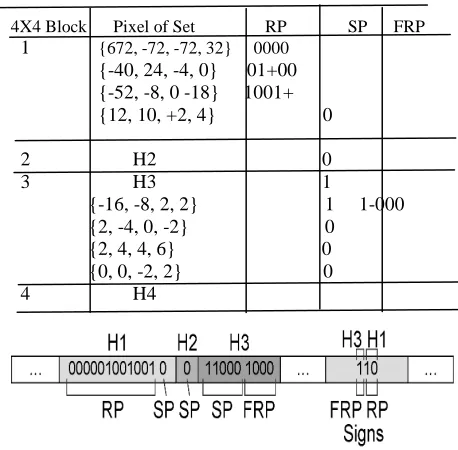
For example consider wavelet coefficients of size 8 x 8. It is divided into 4 x 4 blocks they are denoted as H1, H2, H3, and H4. For example fourth bit plane are explained below.
significant and therefore they are processed in the RP. For the first 2×2 block {672, -72, -72, 32}, magnitude bits “0000” are generated because their
Figure 5: Example of three-level wavelet coefficients used to demonstrate the BP-SPIHT algorithm.
Fourth magnitude bits are all zero. For the second block {-40, 24, -4, 0}, magnitude bits “0100” are generated. In addition, a sign bit “+” is generated because the first significant magnitude bit is generated for pixel 24. Note that the sign bit is stored separately in the end of the bit stream. For the third block {-52, -8, 0, -18}, magnitude bits “1001” are generated. That the first significant magnitude bit is generated for pixel -18, so the sign bit “-” is also generated. The RP for H1 is completed and followed by the SP for H1. The union of 2×2 block {12, 10, -2, 4} and its descendant (=H4) is insignificant in the fourth bit-plane (S4 ({12, 10, −2, 4} ∪ H4) = 0) so that the sorting bit “0” is generated to indicate the insignificance of the block. H1 in the fourth bit-plane does not include any new-significant block, and consequently, no block is processed by the FRP. Next, the bit stream for H2 is generated. H2 is insignificant in the fifth bit-plane, so all the 2×2-bit blocks are insignificant blocks and no 2×2-bit blocks are processed in the RP. In SP, “0” is generated because H2 is also insignificant in the fourth bit-plane. Next, H3 is insignificant in the fifth bit-plane, so it is not processed by the RP. In the SP, H3 is significant in the fourth bit-plane, so the sorting bit “1” is generated and H3 is partitioned into four 2×2-bit blocks and the significance of each 2×2-2×2-bit block is tested. The first 2×2-bit block {-16, -8, 2, 2} is significant, and sorting bit “1” is generated whereas the other 2×2-bit blocks are insignificant, and sorting bit “0” is generated. Block {-16, -8, 2, 2} is a new-significant block which is processed by the FRP
[image:5.595.310.539.249.474.2]generating “1-000.” Next, H4 consists of four insignificant 2×2 blocks, so H4 is not processed by the RP. In the SP, the second “if-condition” is not satisfied, so it is not processed by the SP. Therefore, no bit is generated for H4. The bit stream generated in the fourth bit-plane is shown in Figure 6. The bit results in Table I- are stored from the top row to the bottom row.
TABLE I Bit-stream Results of the Fourth Bit-Plane in Fig. 6 by Pass-Parallel SPIHT
4X4 Block Pixel of Set RP SP FRP
1 {672, -72, -72, 32} 0000
{-40, 24, -4, 0} 01+00 {-52, -8, 0 -18} 1001+ {12, 10, +2, 4} 0
2 H2 0 3 H3 1 {-16, -8, 2, 2} 1 1-000 {2, -4, 0, -2} 0
{2, 4, 4, 6} 0 {0, 0, -2, 2} 0 4 H4
Figure 6 : Bit-stream generated from the example in the fourth bit-plane.
2.3 IMPROVED SPIHT ALGORITHM
A. Description of the algorithm
In improved SPIHT image coding algorithm, First sort descending coefficient matrix, then original coordinates of sorted coefficients in the array are then successively added in one-dimensional array, and corresponding wavelet coefficients put into one-dimensional array. The main drawback is that sorted list is to be taken into consideration while decoding, i.e. to transfer the same values to decoding time. So that it gives more bits output.
0 -4 0 8
2 0 6 0
0 -2 2 4
-2 2 -2 4
672 72 -40 24
72 32 -4 0
-52 -8 12 10
0 -18 -2 4
2 -2 3 -2
1 2 4 2
-1 1 1 3
-2 1 -1 0
-16 -8 2 -4
2 2 0 -2
2 4 0 0
B. Analysis of Improved SPIHT algorithm
Figure 7: A two-level wavelet decomposition of an 8x8 image to demonstrate the Improvement of SPIHT
algorithm (a) Initialization:
The number of current important coefficients; p = 0 Determine the highest bit-plane of coefficient coding.
(b) The sort of wavelet coefficients:
The wavelet coefficient matrix after 3-layer wavelet decomposition was changed into one-dimensional vector and put coordinates into one-dimensional array V,
V= { ( 1, 1) , ( 1, 3) , ( 5, 4) , ( 1, 2) , ( 2, 2) , ( 3, 1) ,( 2, 3) , ( 3, 2) , ( 4, 3) , ( 1, 6) , ( 8, 2) , …….} , L= { 63, 49, 47, - 34, 23, 15, 14, 14, - 14, 13, 11,…….}. (c) To bit plane n = 5, namely quantitative threshold 32, calculate the number of coefficients to be encoded p = 4, according to equation 1, determine the importance of the first four coefficients, output the coding result 1111; obtain coefficients absolute value 32,32,32,32 in the decoder.
For the bit plane n=4, namely quantitative threshold is 16, calculate coefficient number to be encoded for p=5, determine the importance of the first five coefficients in array V, output coding results 111111001; obtain coefficients absolute value 48, 48,32,32,16 in the decoder. Same way remaining passes are down.
3. PROPOSED CODING ALGORITHM: SPIR ALGORITHM
A. Description of the algorithm
Wavelet decomposition applied on image data. In a four-band two-dimensional wavelet transform, the LL band includes the low pass coefficients and represents a soft approximation to the image. The HL, LH and HH bands represent the vertical, horizontal, and diagonal features of the image,
respectively. These three bands convey the details of the image.
First, fix the wavelet decomposed data. Then find out the maximum value in the wavelet coefficients i.e. found out the threshold value
n= log2(max|c(i,j)|)
where c(i,j) are wavelet coefficients. Two ordered lists are used to store the significance information during set partitioning. List of Insignificant Pixels (LIP) and List of Significant Pixels (LSP).
In SPIR(Set Partitioning In Row/Column Wise) algorithm, to check values in row wise. Take Dmat as original data. First check the first row, if any pixel absolute value is greater than or equal to the 2^n then transmit 1 otherwise 0. If transmit bit is 0, then check the second row for signicance (i.e. magnitude of pixel value is greater than or equal to the set threshold). If transmit bit is 1, then check the first half of the row elements. If absolute maximum value of these pixels is greater than or equal to the 2^n then transmit 1otherwise transmit 0. If the transmit bit 0, move this half of the row pixels to a new matrix. If transmit bit is 1, check each pixel value for signicance. If significant transmit 1 followed by sign bit (1 for negative and 0 for positive) and move the index to LSP. If insignificant then transmit 0 and move the index to LIP. Now same significance test is followed for the second half of the row pixels. This procedure is followed for all the rows till the end. This completes the first sorting pass. Next is the second
sorting pass. In this pass threshold is reduced by half
i.e n= n-1. With this threshold first LIP pixels are tested for significance, if signicant transmit 1 followed by sign bit and move the index to LSP otherwise transmit 0. Then check the new matrix (which was formed during the previous sorting pass with insignificant half rows) for signifance. If significant transmit 1 otherwise transmit 0. If significant test all the pixels for significance and if significant transmit 1 followed by sign bit and move the pixel index to LSP. If insignificant move the pixel index to LIP. Now check the left over rows of original matrix whose significant rows during previous pass were moved to a new matrix or LIS or LSP. After second pass follows the refinement pass.
Refinement pass: The nth MSB of the magnitude of
each entry of the LSP, except those added in the current sorting pass, is transmitted. Note that at the end of the first sorting pass, no bits would be transmitted as a part of the refinement pass because the LSP contain no pixel prior to the current sorting pass as in SPIHT.
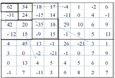
B. Analysis of SPIR algorithm
63 -34 49 10 7 13 -12 7
-31 23 14 -13 3 4 6 -1
15 14 3 -12 5 -7 3 9
-9 -7 -14 8 4 -2 3 2
-5 9 -1 47 4 6 -2 2
3 0 -3 2 3 -2 0 4
2 -3 6 -4 3 6 3 6
Here an image of 8x8 size is considered for matrix analysis and explanation.
Threshold value: n= log2(max|c(i,j)|) n = log2(63) = 5.
In SPIR algorithm, check the first row it’s maximum value is greater than 2^5(32) so, transmit 1. Then check the first half column, it transmit 1, in this each value test (0,0) is 1,0; (0,1) is 1,1 and (0,2) is 1,0 and (0,4) is less then significance value then it transmit 0 move to LIP remain three are move to LSP. Then check the second half column is insignificance value so transmit 0 then move to
Figure 8: A two-level wavelet decomposition of a 8x8 image to demonstrate the SPIR algorithm.
another matrix, it’s size also same size of the original image data. Then first row is deleted. Next check the second row, it is less then significance value so, it transmit 0, three, four also transmit 0. fifth row is max value so, transmit 1,test half column values it transmit 1, then each value in this only (4,3) is 1,0 move to LSP remaining are move to LIP. Second half is 0 then move to another matrix. Finally fifth row is deleted. Remaining rows are less value so, transmit 0.
In first transmission bits are
111011100000011000100000. In first transmission transmit 24 bits. n (threshold value) is decremented by 1.
In second pass, First LIP values are tested, (0,4),(4,1),(4,2),(4,3) it’s less than the threshold value (2^4) so, transmit 0. Next test the another matrix (i.e., last pass testing stage in half column tested time, which are less significance value that is transmit 0 half columns are stored, 1 row second half column and 5 row second half columns). In this test 1 row elements {0,0,0,0,7,13,-12,7} it is not significance so transmit 0 and test the second, third, fourth row are tested it is not significance so, transmit 0.Then test the fifth row{0,0,0,0,4,6,-2,2} its values also less than threshold so, transmit 0. Sixth, seventh, eight rows are not significant then transmit 0.
Next test original matrix (i.e., Wavelet coefficient image data) is tested. In this only check the 2, 3,4,6,7,8 rows. Now test the second row in this max value is greater then significance value so transmit 1, and then test the first half column, in transmit 1 then check the all values in first column{-31,23,14,-13} only (1,0) transmit 1,1 and (1,2) transmit 1,0. Then remains are less than threshold so, transmit 0. Then test second half columns which are less values so, transmit 0. Next test remaining rows which are less value so, transmit 0.
Next test refinement pass, first pass LSP values are tested, in this{(0,0),(0,1),(0,2),(4,3)} values which are greater then 48(i.e., 32+16=48) then transmit 1 else 0. In second pass transmit 000000111110000000001010. In second pass transmission transmit 24 bits. n is decremented by 1. Follow the same process for the remaining pass. Then receive that output bit stream.
For the output bit stream of SPIR encoding with large number of seriate”0” situation, we obtain a conclusion by lot of statistical analysis: ‘0000’ appears with the greatest probability value, usually will be about 1/4.Therefore, divide the binary output stream of SPIRW encode, every 3 bits / 4 bits as a group, every group recorded as a symbol, a total of eight kinds of symbols/16 kind of symbols, statistical probability that they appear, and then encoded using variable-length encoding naturally reached the further compressed. Variable-length coding is Huffman encoding.
4. DATA COMPRESSION: HUFFMAN ENCODING
For the output bit stream of SPIR encoding with a large number of seriate "0" situation, we obtain a conclusion by a lot of statistical analysis:‘0000’ appears with the greatest probability value, usually will be about 1/4.Therefore, divide the binary output stream of SPIR every 4 bits as a group, every group recorded as a symbol, a total of sixteen kinds of symbols, probability that they appear, and then encoded using variable-length encoding naturally. In this paper, variable-length encoding is Huffman encoding.
Using the output bit stream of above example to introduce the new encoding method process.
1. First, divide the binary output stream every 4 bits as a group: 1110 1110 0000 0110 0010 0000 0000 0011 1110 0000 0000 1010 there is no remaining bits. Huffman encoding to record the number of bits that do not participate in group and those remainder
63 -34 49 10 7 13 -12 7
-3 23 14 -13 3 4 6 -1
15 14 3 -12 5 -7 3 9
-9 -7 -14 8 4 -2 3 2
-5 9 -1 47 4 6 -2 2
3 0 -3 2 3 -2 0 4
2 -3 6 -4 3 6 3 6
bits direct output in end. Figure 2 is shown the output bit stream structure of Huffman encoding.
Number of
remaining bits
Bits stream Remain bits Figure 9: The bit stream structure of Huffman encoding 2. The emergence of statistical probability of each symbol grouping results is as follows:
0000 = 5; 0001= 0; 0010= 1; 0011= 1; 0110= 1; 0111= 0; 1000= 0; 1001= 0; 1010= 1; 1011= 0; 1100= 0; 1101= 0; 1110= 3; 1111=0;
3. According to above values, using Huffman encoding, obtain codeword book.
Figure 10: An example of Huffman encoding 0000-1;
1110-01; 0011-0011; 1010-0010; 0110-0001; 0010-0000;
the above code book we can get the corresponding output stream: 01 01 0 0011 0000 0 0 0011 01 0 0010 . Here only 26 bits are obtained to save the 22 bits, in this lot of bits are saved in the Huffman encoding. In decoding the codeword is used with comparison table. Then the original bit stream of algorithm is obtained. Then SPIR decoding is applied on bit stream it is very easy to decode (Decoding is inverse process of the above-mentioned process.).
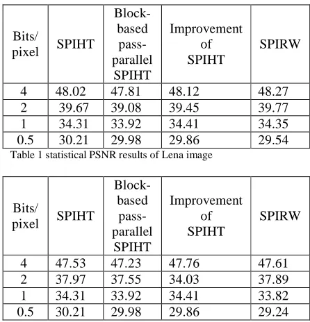
5. EXPERMENTAL RESULTS
In order to verify this algorithm, consider Lena, Water-lilies example images of size 512*512*8 bits/pixels as input.
1. To observe the output errors MSE and PSNR. Here the MSE (i.e., the cumulative square error between the compressed image and original image) is low. If MSE is low then lower the error so, higher the PSNR (represents a measure of the peak signal to noise ratio). In this SPIR algorithm, before at 0.5 bpp the bits of the image is more and same PSNR for each pass. Increasing the bpp, coding bits and PSNR should be better compare to SPIHT.
2. The main aspect in the paper, proposed algorithm is easy to understand. And better compression ratio and more over all values are received at the output without any loss of data.
Bits/
pixel SPIHT
Block-based pass- parallel
SPIHT
Improvement of SPIHT
SPIRW
4 48.02 47.81 48.12 48.27
2 39.67 39.08 39.45 39.77
1 34.31 33.92 34.41 34.35
[image:8.595.308.531.303.535.2]0.5 30.21 29.98 29.86 29.54
Table 1 statistical PSNR results of Lena image
Bits/
pixel SPIHT
Block-based pass- parallel
SPIHT
Improvement of SPIHT
SPIRW
4 47.53 47.23 47.76 47.61
2 37.97 37.55 34.03 37.89
1 34.31 33.92 34.41 33.82
[image:8.595.73.280.341.467.2]0.5 30.21 29.98 29.86 29.24
Table 2 statistical PSNR results of Water-lilies image
6. CONCLUSION
This proposed algorithm is simpler and effective method combined with Huffman encoding for further compression saves a lot of bits in the image data transmission and gives the best performance for attaining high PSNR. The quantitative PSNR values in case of the SPIR algorithm are better for taken images.The algorithm is easy to understand and to implement also. Bits are nearly same as SPIHT algorithm encoding bits. This shows that the proposed algorithm is more suitable for the robust storage of data.
7. FUTURE SCOPE
SPIHT and so on. But the emergence of medical imaging and explode of images in this field has resurfaced the need to tailor made medical image compression techniques that can attain a very high compression ratio, without compromising to the medical information stored in the images, for patient centric medical applications. The future scope of this work is to include techniques for effective storage of data and newly developed cryptographic algorithms to make it more secure and effective.
ACKNOWLEDGEMENT
The authors would like to thank the NOVA INSTITUTE OF TECHNOLOGY for testing the algorithm in image processing applications.
REFERENCES
[1] Wei Li, Zhen Peng Pang and Zhi Jie Liu. SPIHT algorithm combined with Huffman encoding. Third International Symposium on Intelligent Information Technology and Security Informatics 2010.
[2] Raghuveer M. Rao and Ajit S. Bopardikar. Intrduction to Wavelet Theory and Applications. [3] Rafael C. GONZALEZ Richard E. WOODS.
Digital image processing: second ed [M]. Beijing Publishing House of Electronics Industry 2002. [4] Marc ANTONINI Michel BARLAUD Pierre
MATHIEU et al. Image coding using wavelet transform [J]. IEEE Trans. Image Processing 1992
1(2) 205-220.
[5] Cheng Li-chi, Wang Hong-xia, Luo Yong. Wavelet theory and applications. Beijing: Science Press,2004(Chinese).
[6] J. M. SHAPIRO. Embedded image coding using zerotree of wavelets coefficients [J]. IEEE Trans. Signal Processing 1993 41(12) 3445-346 2. [7] Amir SAID William A.PEARLMAN. A new fast
and efficient image codec based on set partitioning in hierarchical trees [J]. IEEE Transactions On Circuits and Systems for Video Technology 1996 6(3) 243-250.
[8] FAN Qi-bin. Wavelet analysis. Wuhan: Wuhan University Press, 2008.
[9] Yongseok Jin, Member, IEEE, and Hyuk-Jae Lee.A block based pass parallel spiht algorithm. IEEE TRANSACTIONS ON CIRCUITS AND SYSTEMS FOR VIDEO TECHNOLOGY, VOL. 22, NO. 7, JULY 2012.
[10] Li Baiping, Zhang Xueyan. Improvement of SPIHT Algorithm. 2011 Second International Conference on Intelligent System Design and Engineering Application.
[11] Theory Wang Huiyuan.Digital Image
Communication and
Technology[M].Beijing.Defense Industry Publisher,2000
[12] Wheeler FW. Pearlman W A. SPIHT image compression with-out lists[ C] / /Proc.of the International Conf. on Acoustics, Speech and Signal Processing. Vancouver, Canada, 2000.2047-2050.
[13] Su C Y, Wu B F. Alowmemory zerotree coding for arbitrarily shaped objects [ J] . IEEE Transactions on Image Processing.2003, 12( 3): 271 282.