298
Evaluation of Temperature Distribution of Solid State
Welded Dissimilar Alluminium Alloy Joints
*Tamilarasan S
1, Babu N
2PG Scholar, ACGCET Karaikudi1, Assistant Professor ACGCET Karaikudi2. Email: [email protected], [email protected]
Abstract-AA 5059 aluminium alloy is a new grade of high strength aluminium alloy in the non-heat treatable category. This alloy is best suited for military applications because of high strength to weight ratio and high toughness. Also this high magnesium content aluminium alloy is used to make ship hull structure due to its good corrosion resistance and strength. Heat treatable AA6061-T6 aluminium alloy (Al-Mg- Si alloy) has gathered wide acceptance in the fabrication of light weight structures requiring high strength to weight ratio and good corrosion resistance. Friction stir welding is a solid state welding process and it is a suitable method for joining non-ferrous materials such as aluminium alloys. The objective of this work is to analyze the temperature and residual stress distribution in butt welding of dissimilar aluminium alloy of 5 mm thick plates during friction stir welding by using ANSYS. In the present investigation, the high strength AA5059 and medium strength 6061-T6 is aimed to weld by the FSW process; to ascertain the optimal mechanical properties by varying the rotational speed, welding speed and axial force. The optimised parameters used in this friction stir welding process are welding speed 25 mm/min, rotational speed 1000rpm, axial force 5 KN.
Key words: Friction Stirs Welding, Aluminium Alloys (AA), ANSYS
1 INTRODUCTION
Welding is a process of joining metallic parts by heating to a suitable temperature with or without the application of pressure and with or without application of filler material. It is basically a permanent joining process. The process of welding can be classified on the basis of heat generation, barring the process of welding which do not use heat for joining as pressure only is sufficient for the exchange of surface molecules to make the joint. Cold welding process which is completed with the help of pressure applied only. Generally adopted for ductile and malleable metals of less thickness. Friction Stir Welding (FSW) is a relatively new joining process. Since FSW is essentially a solid-state, without melting,
High quality weld can generally be fabricated with absence of solidification cracking, porosity, oxidation, and other defects typical to traditional fusion welding.
FSW can be used to join many types of similar and dissimilar material combinations provided that tool can be developed to operate compatibly in the hot working temperature range of the work pieces. FSW also has potential for bonding many materials that are difficult or impossible to be joined by more conventional methods, including alloys that are susceptible to solidification cracking, high-strength steels, metal-matrix composites, and other advanced alloys. For many conventionally welded aluminium alloys the
fusion zones are typically weaker than the base metal.
However, FSW offers a significant quality advantage that it is possible to make welds where the strength of the fusion zone is identical to that of the base metal alloy. Additionally, because the energy input used for FSW is relatively low (no melting occurs), the heat-affected zone (HAZ) or thermo mechanically affected zone (TMAZ) and residual stresses associated with the welds are relatively small. Lower residual stresses mean that distortion associated with FSW is not a large concern as in conventional welding.
2 EXPERIMENTAL PROCEDURE
The two work pieces to be welded, with square mating (faying) edges are clamped on a rigid backing plate. The clamping prevents the any movement of work pieces during welding. The shank, shoulder and pin form a welding tool, and this tool can be rotated to a prescribed speed and may be tilted normal with respect to the work piece.
299 The parent metal was prepared into sizes
of 150 × 75 × 5 mm for welding. The pin is withdrawn on reaching the end which leaves a keyhole. The pin is forced or plunged into the work piece until the shoulder contacts the surface of the work piece. As the tool descends further, its shoulder surface touches the top surface of the
work piece and creates heat. Table 1,2&3 shows the chemical, Mechanical properties and process parameter.
Table 1. Chemical composition (wt. %) of base material
Element Si Cu Mn Mg Cr Zn Ti Al
AA 6061 21 0.17 0.04 0.95 0.066 0.014 0.022 Remain.
AA 5059 0.041 0.003 0.933 5.21 0.5-0.6 <0.001 0.489 Remain.
Table 2.Mechanical properties
Element Ultimate tensile
strength (MPa)
0.2% Yield strength
(MPa)
Elongation in 50mm gauge length (%)
Hardness (HV 0.05 kg@ 15
sec)
AA 6061 310 276 14 107
AA 5059 385 290 16 123
Table 3. FSW parameters
Sl.no Input variables Values
1 Rotational speed(rpm) 1000
2 Welding Speed(Mm/Min) 25
3 Axial force(kN) 5
3 NUMERICAL ANALYSIS
The Numerical Analysis technique is a Finite Element Method (FEM) used to perform Finite Element Simulation of any given physical phenomenon and irregular domain. This numerical method used for solve the problems of Engineering and Mathematics. FEM is used
particularly for solve the problems involving complicated geometries, loading and material properties which cannot be easily solved by analytical method.
3.1 Finite Element Model
Finite Element Method is a basic analysis technique for resolving and substituting complicated problems by simpler ones. Finite element method being a flexible tool is used in various industries to solve several practical engineering problems. In this simulation I was choose SOLID 70 element for my suitable solution. The FEA MESHED model shown in the fig1.
3.2Need For Finite Element Method
To predict the behaviour of structure, three tools adopted such as analytical, experimental and numerical methods. The analytical method is used for the rectangular sections of geometri entities or primitives where the component geometry is expressed mathematically. The experimental method is used for finding the unknown parameters of interest. But the experimentation requires testing equipment and a specimen for each behaviour.
300
Fig. 1.Meshed model
4 RESULT AND DISCUSSION
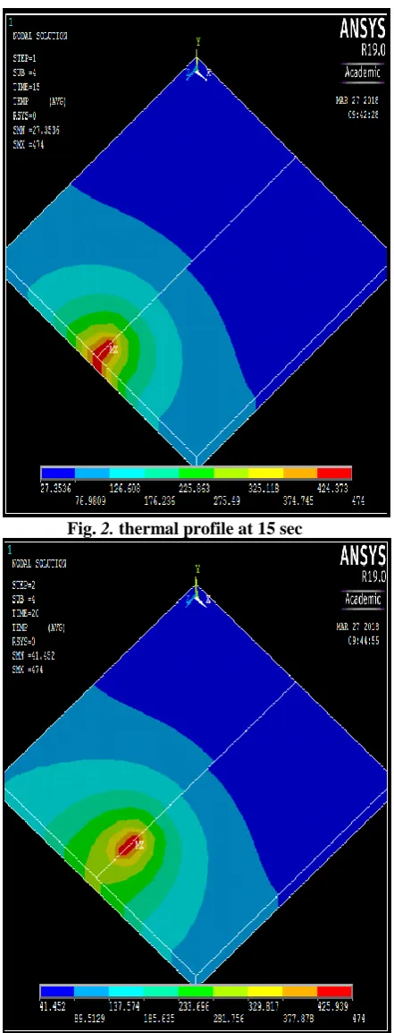
4.1 Temperature Distribution
The temperature distribution was done by using the ANSYS FEA tool by four sub steps by using transient analysis. Because of the thermal analysis was not a static condition, the temperature changes depends upon the time. The FSW welding conducted at the room temperature of 25 degree Celsius. When the welding started the minimum temperature was slightly increased from the room temperature.
The minimum temperature changes during the welding time was 27.35˚c, 41.45˚c, 54.77˚c, 72.1˚c. The temperature distribution (fig 2,3,4&5) was used to found how the material distribute the temperature at the time of welding.
Fig. 2. thermal profile at 15 sec
[image:3.595.72.292.99.401.2] [image:3.595.314.535.100.678.2]301
Fig. 4. thermal profile at 25 sec
Fig. 5. thermal profile at 30 sec
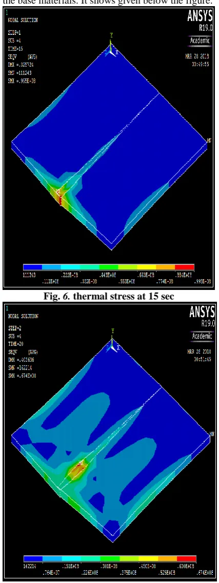
4.2 Thermal Stress
The thermal model was developed by FEA simulation. And the thermal result act as the input file to find the residual stress in ANSYS. The temperature distribution was founded by the transient analysis at the same procedure followed
for this condition. In this simulation we got the stress distribution value was 67 MPa to 99 MPa at 15 sec to 30 sec. The obtained thermal stress (fig
6,7,8,9) value was less than the yield strength of
the base materials. It shows given below the figure.
Fig. 6. thermal stress at 15 sec
[image:4.595.72.291.103.670.2] [image:4.595.313.527.156.725.2]302
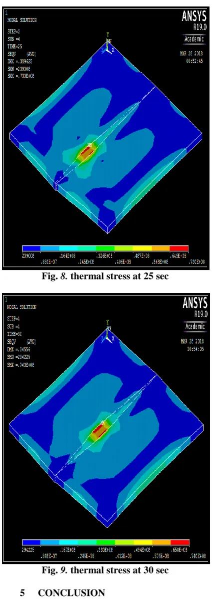
Fig. 8. thermal stress at 25 sec
Fig. 9. thermal stress at 30 sec
5 CONCLUSION
The above investigation was done by the simulating software of ANSYS. In this case the thermal profile and residual stress was done at 15 sec to 30 sec by transient analysis.
The temperature distribution was founded at the mid-point of the stir zone was 474°c and the minimum temperature was 27°c. The residual stress distribution was also
less than the base material yield strength(max 99MPa).
REFERENCE
[1] NarayanasamyBabu.; Narayanan Karunakaran.;
ViswalingamBalasubramanian.; (2017) , ―Numerical predictions and experimental investigation of the temperature distribution of friction stir welded AA 5059 aluminium alloy joints‖ International Journal of Materials Research , Vol.10 (2017).
[2] M.N. Ahmad Fauzi, M.B. Uday, H. Zuhailawati, A.B. Ismail (2010) , ―Microstructure and mechanical properties of alumina-6061 aluminum alloy joined by friction welding‖ journel of Materials and Design, Vol.31 (2010) 670–676. [3] EmelTaban.; Jerry E. Gould.; John, C.;
Lippold. (2010), ―Dissimilar friction welding of 6061-T6 aluminum and AISI 1018 steel: Properties and microstructural characterization‖ Journal of Materials and Design, Vol.31 (2010) 2305–2311. [4] Arivazhagan, N.; Surendra Singh.; Satya
Prakash.; G.M. Reddy. (2011) ,―Investigation on AISI 304 austenitic stainless steel to AISI 4140 low alloy steel dissimilar joints by gas tungsten arc, electron beam and friction welding‖ Journal of Materials and Design, Vol.32 (2011) 3036–3050.
[5] Andreza, S.; Franchim.; Fernando, F.; Fernandez,; Dilermando, N.; Travessa. (2011) ,― Microstructural aspects and mechanical properties of friction stir welded AA2024-T3 aluminium alloy sheet‖ Journal of Materials and Design, Vol.32 (2011) 4684–4688.
[6] SubbaraoChamarthi.; NagarjunaThota and Rohan Kalia. (2015), ―Analysis on Parameters of Friction Stir Welding when Joining Aluminum Alloy to Steel‖ Journal of Material Science and Mechanical Engineering (JMSME), Vol.2, January-March, 2015 pp.158-161.
[image:5.595.70.283.98.700.2]303 Robotics Research,ISSN 2278 – 0149
Vol.1, No.2, July 2012.
[8] C.M. Chen.; R. Kovacevic.; (2003), ―Finite element modeling of friction stir welding—thermal and thermomechanical analysis‖ International Journal of Machine Tools & Manufacture, Vol.43 (2003) 1319–1326.
[9] AnthatiNaveenkumar, B.; EswaraiahDr, M.; Chandra Sekhar Reddy. (2017), ―Experimental Investigations and Finite Element Analysis of Friction Stir Welding of Various Aluminium Alloys‖ International Journal of Engineering Research &Technology, Vol.6 ISSN: 2278-0181.