Error Resilient Video Compression Using
Behavior Models
Jacco R. Taal
Information and Communication Theory Group, Department of Electrical Engineering, Mathematics and Computer Science, Delft University of Technology, Mekelweg 4, 2628 CD Delft, The Netherlands
Email:[email protected]
Zhibo Chen
Imaging Technology Group, IMNC, Sony Corporation, 6-7-35 Kitashinagawa, Shinagawa-Ku, Tokyo 141-0001, Japan Email:[email protected]
Yun He
Video Communication Research Group, Electronic Engineering Department, Tsinghua University, 11-425 East Main Building, 100084 Beijing, China
Email:[email protected]
R. (Inald) L. Lagendijk
Information and Communication Theory Group, Department of Electrical Engineering, Mathematics and Computer Science, Delft University of Technology, Mekelweg 4, 2628 CD Delft, The Netherlands
Email:[email protected]
Received 1 December 2002; Revised 26 September 2003
Wireless and Internet video applications are inherently subjected to bit errors and packet errors, respectively. This is especially so if constraints on the end-to-end compression and transmission latencies are imposed. Therefore, it is necessary to develop methods to optimize the video compression parameters and the rate allocation of these applications that take into account residual channel bit errors. In this paper, we study the behavior of a predictive (interframe) video encoder and model the encoders behavior using only the statistics of the original input data and of the underlying channel prone to bit errors. The resulting data-driven behavior models are then used to carry out group-of-pictures partitioning and to control the rate of the video encoder in such a way that the overall quality of the decoded video with compression and channel errors is optimized.
Keywords and phrases:behavior model, rate distortion, video coding, error resilience.
1. INTRODUCTION
Although the current video compression techniques can be considered mature, there are still many challenges in the de-sign and operational control of compression techniques for end-to-end quality optimization. This is in particular true in the context of unreliable transmission media such as the Internet and wireless links. Conventional compression tech-niques such as JPEG and MPEG were designed with error-free transmission of the compressed bitstream in mind. With such unreliable media, not all bit or packet errors may be cor-rected by retransmissions or forward error correction (FEC). Depending on the kind of channel coder, residual channel er-rors may be present in the bitstream after channel decoding.
In most practical packet network systems, packet retransmis-sion corrects for some, but not all, packet losses. Classic rate control, such as TM.5 in MPEG [1], can be used to con-trol the video encoder according to the available bit rate of-fered by the channel coder; adaptation to the bit error rate by inserting intracoded blocks is nevertheless not incorpo-rated in TM.5. Other methods that control the insertion of intracoded blocks exist [2].
end-to-end quality optimization, it comes at the price of a signif-icant complexity increase. Furthermore, nearly all of these approaches only work with specific or nonstandard network protocols and with a specific video encoder and/or decoder.
The second class represents many approaches where the source coder has no (or limited) control of the network layer. It is important to understand that these approaches can not be generally optimal since the channel coder and the source coder are not jointly optimized. Since there is no joint opti-mization, the only thing the source coder can do is to adapt its own settings according to the current behavior of the net-work layer. In many applications, joint optimization is im-possible because none of the standard network protocols (IP, TCP, and UDP) support this. Even though the source coder has no or limited control over the network layer, the rate con-trol algorithm can adapt to the available bit rate and to the amount of residual bit errors or packet losses. Such a control algorithm needs a model describing the effects of bit errors or packet losses on the overall distortion.
The third class contains the approaches advocated in [5,6]. In these approaches, the best properties of the first two classes are combined. Here, the authors propose to limit the integration to joint parameter optimization, so that there is no algorithmic integration. In previous work at Delft Uni-versity of Technology [7], an efficient overall framework was proposed for such joint parameter optimization from a quality-of-Service (QoS) perspective. This framework re-quires high-level and abstract models describing the behav-ior of source and channel coding modules. However, this framework had not yet been tested with a real video coder and with a real behavior model.
In this paper, we propose such a behavior model for de-scribing source-coding characteristics, giving some informa-tion about the channel coder. Although this model is de-signed to be used in a QoS setup, it may also be used to op-timize the encoders settings when we only have knowledge of, but no control over, the current channel (as a second class approach).
With this behavior model, we can predict the behavior of a source coder in terms of the image quality related to the channel coder parameters: the bit rate, the bit error rate (BER), and the latency. To be applicable in a real-time and perhaps low power setup, the model itself should have a low complexity and should not require that many frames have to reside in a buffer (low latency).
We evaluate the behavior models with one type of pro-gressive video coder. However, we believe that other coders can be described fairly easily with our methods as well, since we try to describe the encoders at the level of behavior rather than at a detailed algorithmic or implementation level. In Section 2, we first discuss our combined source-channel cod-ing system; the problem we wish to solve, and we describe the source and channel coders on a fairly high abstraction level. From these models, we can formulate the end-to-end quality control as an optimization problem, which we will discuss inSection 3.Section 4describes in depth the construction of the proposed models. InSection 5, our models are validated in a simulation where a whole group of pictures (GOP) were
transmitted over an error prone channel.Section 6concludes this paper with a discussion.
2. PROBLEM FORMULATION
To optimize the end-to-end quality of compressed video transmission, one needs to understand the individual com-ponents of the link. This understanding involves knowledge of the rate distortion performance and the error resilience of the video codec, of the error correcting capabilities of the channel codec, and possibly of parameters such as delay, jit-ter, and power consumption. One of the main challenges in attaining an optimized overall end-to-end quality is the determination of the influence of the individual parameters controlling the various components. Especially because the performances of various components depend on each other, and the control of these parameters is not straightforward.
In [4,5,8,9], extensive analyses of the interaction and trade-offs between source and channel coding parameters can be found. A trend in these approaches is that the un-derlying components are modeled at a fairly high abstrtion level. The models are certainly independent of the ac-tual hardware or software implementation but they also be-come more and more independent of the actual compres-sion or source coding algorithm used. This is in strong con-trast to the abundance of joint source channel coding ap-proaches, which typically optimize a particular combination of source and channel coders, utilizing specific internal al-gorithmic structures and parameter dependencies. Although these approaches have the potential to lead to the best per-formance, their advantages are inherently limited to the par-ticular combination of coders and to the conditions (source and channel) under which the optimization was carried out. In this paper, we refrain from the full integration of source and channel codecs (i.e., the joint source-channel coding approach) but we keep the source and channel coders as much separate as possible.
The interaction between source and channel coders and, in particular, the communication of key parameters is encap-sulated in a QoS framework. The objective of the QoS frame-work is to structure the communication context parameters between OSI layers. In the scope of this paper, the context can be defined not only by radio/Internet channel conditions, but also by the demands of the application or device concerning the quality or the complexity of the video encoding. Here we discuss only the main outline of the QoS interface. A more detailed description of the interface can be found in the liter-ature (see [6,7]).
Wireless channel
Figure1: QoS concept: different (OSI)layers are not only
commu-nicating their payloads, they are also controlled by QoS controllers that mutually negotiate to optimize the overall performance.
with the QoS controller of the channel coder. Based on the behavior description of the source and channel coding mod-ules, the values of these parameters are optimized by the QoS controller. In a practical system, this optimization takes into account context information about the application (e.g., maximum latency) and about the channel (e.g., throughput at the physical layer). The application may set constraints on the operation of the lower layers, for instance, on the power consumption or the delay. In this paper, we assume that the only constraint set by the application is the end-to-end delay Ta.
In order to implement the QoS Interface/controller con-cept, the following three problems need to be solved.
(i) The key parameters must be optimized over different (OSI) layers. We have developed the “adaptive resource contracts” (ARC) approach for solving this problem. ARC exchanges the key parameters between two layers such that after a negotiation phase, both layers agree on the values of these parameters. These key parame-ters represent the trade-offs that both layers have made to come to a joint solution of the optimization. A de-tailed discussion of ARC falls outside the scope of this paper. We refer to [6,7,10].
(ii) The behavior of the source and channel coders should be modeled parametrically such that joint optimiza-tion of the key parameters can take place. At the same time, an internal controller that optimizes the per-formance of the source and channel coders indepen-dently, given the already jointly optimized key param-eters, should be available. The emphasis in this paper is on the modeling of the video coder behavior. (iii) An optimization procedure should be designed for
selecting the parameters internal to the video codec, given the behavior model and the key parameters. We do not emphasize this aspect of the QoS interface in this paper as we believe that the required optimization procedure can be based on related work as that in [11].
In previous work and analyses [6,7], the source coder was modeled as aprogressive encoder, which means that with every additionally transmitted bit, the quality of the received decoded information increases. Therefore, the most impor-tant information is encoded at the beginning of the data stream, and the least important information is encoded at the end. In principle, we believe that any progressive encoder can be described with our models. To keep things simple from a compression point of view, we use the common inter-frame coding structure (with one interinter-frame per GOP, mul-tiple predictively encoded interframes, and no bidirectional encoded frames). The actual encoding of the (difference) frames is done by a JPEG2000 (see [12]) encoder, which suits our demand for progressive behavior. Figure 2shows the typical block diagram of this JPEG2000-based interframe coder. In this paper, we exclude motion compensation of in-terframes for simplicity reasons. The internal parameters for this video encoder are the number of frames in a GOPN, and the bit ratesrifor the individual frames. SymbolsXiand Xi−1denote the current frame and the previous frame,X de-notes a decoded frame, and ˜Xdenotes a decoded frame at the decoder side, possibly with distortions caused by resid-ual channel errors. Symbols ˜Dqand ˜Dedenote the quantiza-tion distorquantiza-tion and the distorquantiza-tions caused by residual chan-nel errors (named “chanchan-nel-induced distortion” hereafter), respectively.
In this work, the channel coder is defined as an ab-stract functional module with three interface parameters. The channel coder has knowledge of the current state of the channel which it is operating on. Therefore, it can optimize its own internal settings using behavior models. Such a chan-nel coder may use different techniques like FEC and auto-matic repeat requests (ARQ) to protect the data at the pense of added bit rate and increased delay (latency). The ex-act implementation is nevertheless irrelevant for this paper. From here we will assume that the error protection is not perfect because of latency constraints; therefore the residual BER may be non zero. The behavior models can be obtained by straightforward analysis of the channel coding process [5].
3. SOURCE ENCODER OPTIMIZATION CRITERION
At this point, we assume that we have a behavior model for our video encoder. The development of this behavior model is the subject ofSection 4. Given the behavior model, we can minimize the average end-to-end distortion ˆDgiven the con-straints imposed by the QoS interface. In our work, the QoS Interface negotiates three key parameters between source and channel coder, namely,{R, BER,Tc}, with
(i) R: the available bit rate for source coding (average number of bits per pixel);
(ii) the residual BER: the average bit error rate after chan-nel decoding;
I-frame
Video encoder Channelcoder Channelerrors BER
Figure2: Simple video coding scheme. The “frame encoder” and “frame decoder” blocks represent the single frame encoder and decoder.
The “frame buffer” is needed for the predictively encoded interframes.
The resulting source coding optimization problem now becomes the minimization of the distortionD, which can be formulated as follows:
min Isrc
DIsrc| {R, BER,Tc}. (1)
Here,Isrc denotes the set of internal source coder parame-ters over which the performance of the encoder must be op-timized, given the key parameters {R, BER,Tc}. The actual set of internal parameters to be considered depends on the encoder under consideration and the parameters included in the encoders behavior model. In this paper, we consider the optimization of the following internal parameters:
(i) N, the length of the current GOP. Each GOP starts with an intraframe and is followed byN−1 predictively encoded interframes;
(ii)r = {r0,r1,. . .,rN−1}: the target bit rate for each indi-vidual frame in a GOP.
The encoder parameterNrelates to the coding efficiency and the robustness of the compressed bitstream against the remaining errors. The larger isN, the higher the coding ef-ficiency, because more interframes are encoded. At the same time, the robustness of the stream is lower due to the propa-gation of decoded transmission errors.
On the other hand, in order to optimize the settings
{N,r} for Nmax frames, these Nmax frames have to be buffered, thereby introducing a latency. In our approach, the QoS interface prescribes the maximum end-to-end latency Ta(seconds), and we assume that the channel coder will have an end-to-end latency ofTc(seconds), from the channel en-coder to the channel deen-coder, including transmission. Anal-ysis of the whole transmission chain gives the following ex-pression for the total end-to-end latency:
Ta=N−f 1
r +Te+Tc+ B
R, (2)
where fris the frame rate of the video sequence that is
en-coded andTe is the upper bound of the time it takes to en-code a frame. Finally B/Ris the transmission time for one frameB/R; the maximal number of bits to describe a frame divided by the channel coding bit rateR.
We can now find an expression for the maximal num-ber of frames that can be in the buffer while still meeting the end-to-end latency constraintsTa. ClearlyB/Ris only known after allocating the rate for each frame. We suggest taking the worst case value forB(i.e., calculated from the maximal bit rate setting). The same goes forTEwhere we suggest to take the worst case encoding time per frame,
Nmax=1 +
Ta−Te−Tc−BR
fr. (3)
In each framei, two kinds of distortion are introduced: (1) the quantization error distortion, denoted byDqand (2) the channel-induced distortion caused by bit errors in the received bitstream, denoted by De. With our optimization problem, we aim to minimize the average distortion, which is the sum of individual distortions of a GOP divided by the length of the group:
Following [5], we assume that Dq and De within one frame are mutually independent. Although (4) is a simple additive distortion model, the distortion of a frame is still de-pendent on that of the previous frames because of the inter-frame prediction. Therefore, in our models, we have to take into account the propagation of quantization and channel-induced distortions.
Taking the above parameters into account, we can now rewrite (1) as the following bit rate allocation problem:
subject to
1 N
N−1
i=1
ri=R, N≤Nmax. (6)
The approach that we follow in this paper is to optimize the bit rate allocation problem (5) and (6) based on two frame-level parametric behavior models. The first (rate dis-tortion) model parametrically describes the relation between the variance of the quantization distortion and the allocated bit rate based on the variance of the input frames. The sec-ond (channel-induced distortion) model parametrically de-scribes the relation between the variance of the degradations due to transmission and the decoding errors based on the variance of the input frames and theeffective(BER).1
4. RATE DISTORTION MODEL
In this section, we first propose a behavior model for the rate distortion characteristicsDqof video encoders and then pro-pose a model for distortion caused by residual channel errors including the error propagationDe.
There are two approaches for modeling the rate distor-tion (RD) behavior of sources. The first approach is the an-alytical approach, where mathematical relations are derived for the RD functions assuming certain (stochastic) proper-ties of the source signal and the coding system. Since these assumptions do not often hold in practice, the mismatch be-tween the predicted rate distortion and the actual rate dis-tortion is (heuristically) compensated for by empirical esti-mation. The second is the empirical approach where the RD functions are modeled through regression analysis of the em-pirically obtained RD data. The rate distortion model pro-posed in [5] is an example of an empirical model of the dis-tortion of an entire encoder for a given bit rate.
In our work, we anticipate the real-time usage of the con-structed abstract behavior models. At the same time, we want to keep the complexity of the models low. This limits the amount of preprocessing oranalysisthat we may do on the frames to be encoded. Therefore, we will base our behavior models on variance information only. In particular, we will use
(i) the variance of the frame under consideration denoted by VAR[Xi],
(ii) the variance of the difference of two consecutive frames denoted by VAR[Xi−Xi−1].
4.1. Rate distortion behavior model of intraframes
It is well known that for memoryless Gaussian distributed sourcesX with variance VAR[X], the RD function is given by
r(Dq)=1
2log2
VAR[X] Dq
, (7)
1By “effective bit error rate” we mean the residual bit error rate, that is,
the bit errors that are still present in the bitstream after channel decoding.
or when we invert this function by
Dq(r)=VAR[X]2−2r. (8)
Empirical observations show that for the most common audio and video signals under small distortions, the power function−2r gives an accurate model for the behavior of a compression system especially in terms of the quality gain per additional bit (in bit rate terms) spent. For instance, the power function−2r leads to the well-known result that, at a sufficiently high bit rate, for most video compression systems we gain approximately 6 dB per additional bit per sample.
However, for more complicated compression systems and especially for larger distortions, the simple power func-tion does not give us enough flexibility to describe the em-pirically observed RD curves, which usually give more gain for the same increase in bit rate. Since there is basically no theory to rely on for these cases without extremely detailed modeling of the compression algorithm, we instead propose to generalize (8) as follows:
Dq(r)=VAR[X]2f(r). (9)
The function f(r) gives us more freedom to model the (RD) behavior at the price of regression analysis or online parameter estimation on the basis of observed rate distor-tion realizadistor-tions. The choice of the kind of the funcdistor-tion used to model f(r) is a pragmatic one. We have chosen a third-order polynomial function. A first- or second-third-order function was simply too imprecise, while a fourth-order model did not give a significant improvement and higher-order mod-els would defeat our objective of finding simple and generic models. Clearly there is a trade-offbetween precision (high order) and generality (low order).
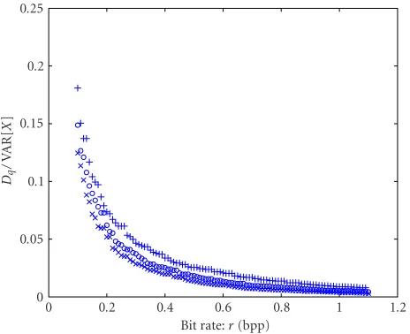
InFigure 3, we show the (RD) curve of the experimen-tally obtained ˜Dq(r) for the JPEG2000 compression of the first frame of the Carphone sequence for bit rates between 0.05 and 1.1 bits per pixel (bpp). The solid line represents a third-order polynomial fit of f(r) on the measured values. This fit is much better than the linear function f(r)= −2r. The following function was obtained for the first frame of the Carphone sequence:
Dq(r)=VAR[X]2−4.46r3+11.5r2−12.7r−1.83. (10)
Bit rate:r(bpp)
0 0.2 0.4 0.6 0.8 1 1.2
Dq
/
VA
R
[
X
]
0 0.1 0.2 0.3 0.4 0.5 0.6 0.7
Figure3: RD curve for the first frame in Carphone. The crosses
(×) are the measured normalized distortions ˜Dqand the solid line
corresponds to the fitted function 2f(r). The dashed-dotted line
cor-responds to the RD model 2−2r.
Bit rate:r(bpp)
0 0.2 0.4 0.6 0.8 1 1.2
Dq
/
VA
R
[
X
]
0 0.05 0.1 0.15 0.2 0.25
Figure4: Intraframe RD curve for the first frame of Carphone (×), frame 60 of Carphone (◦), and the first frame of Foreman (+).
4.2. Rate distortion behavior model of interframes
For modeling the (RD) behavior of interframes, we propose to use a model similar to the one in (9), but with a different polynomialg(r),
Dqri=VARXi−Xi−12g(ri). (11)
Here, Xi−1 denotes the previously decoded frame i − 1, whereas with intraframes, a third-order polynomial was needed to predict f(r) accurately enough. With interframes, a second-order polynomial was sufficient to predictg(r). The reason for this can be found in the fact that interframes are
Dq(ri−1)
0 500 1000 1500 2000 2500 3000 3500
VA
R
[
Xi
−
Xi−
1
]
0 500 1000 1500 2000 2500 3000 3500
Figure5: The relationship between the variance of frame difference VAR[Xi−Xi−1] and the quantization distortion ˜Dq(ri−1). The fitted
line describes VAR[Xi−Xi−1]=VAR[Xi−Xi−1] +κDq(ri−1).
less correlated than intraframes. Therefore,g(r) is more sim-ilar to the theoretical−2rthan f(r).
In (11), VAR[Xi −Xi−1] is the variance of the diff er-ence between the current frameiand the previouslyencoded
framei−1. Since the latter is only availableafterencoding (and thus after solving (5) and (6)), we need to approximate VAR[Xi−Xi−1]. Obviously we have
VARXi−Xi−1=EXi−Xi−12
=EXi−Xi−1−Xi−1−Xi−12
=VARXi−Xi−1+Dqri−1
−2E(Xi−Xi−1Xi−1−Xi−1. (12)
The last term on the right-hand side of (12) cannot be easily estimated beforehand and should therefore be approximated. We collapse this entire term into a quantity that only depends on the amount of quantization errorsDqfrom the previous frame, yielding
VARXi−Xi−1=VARXi−Xi−1+κDqri−1. (13)
We expect the quantization noise of frameXi−1to be only slightly correlated with the frame difference between frames Xi−1andXi. Therefore, we expect the value ofκto be some-what smaller than one. Note that by combining (13) and (11), Dq is defined recursively, thereby making (5) and (6) a dependent optimization problem.
Bit rate:r(bpp)
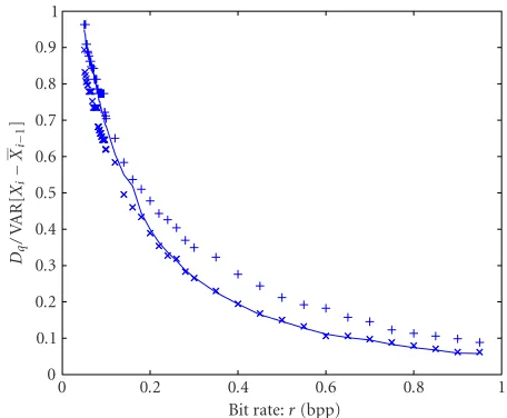
Figure6: Average RD curve for the first interframe of Carphone.
The crosses (×) are the measured normalized distortions ˜Dq(ri) and
the solid line corresponds to the fitted function 2g(r). The
dashed-dotted line corresponds the RD model 2−2r.
We observed similar behavior for other sequences such as Susie and Foreman as well. We therefore postulate that (13) is an acceptable model for calculating the variance VAR[Xi− Xi−1] as needed in (11).
The varianceXi−Xi−1consists of two terms: the quan-tization distortion of the previous frames, and the frame dif-ference between the current and the previous frame. These two terms might show different RD behavior, that is, a sep-arate g(r) for both terms. However, we assume that both signals show the same behavior since they are both frame-difference signals by nature and not whole frames. The model for predicting the distortion of an interframe now becomes
Dq(ri)=VARXi−Xi−1+κDqri−12g(ri). (14)
Figure 6shows the experimentally obtained RD curve to-gether with a fitted curve representing our model (14). Since this RD curve should not only be valid for varying bit rate ri but also for varying propagated quantization distortion Dq(ri−1), we also vary the bit rate of the previous frameri−1. Both rates were varied from 0.05 to 0.9. Each value ofDq(ri) is an average over all settings of ri−1. For completeness, the theoretic curve (8) is shown as well. The function that de-scribes the RD behavior for these frames is
Dq(ri)=VARXi−Xi−1+κDqri−123.86ri2−8.15ri−0.26. (15) We then compare the curves for different frames.Figure 7 shows the RD curve for the first frame difference of Carphone and the RD curve for the first frame difference of Foreman as well as the average RD curve for the first ten frame differences of Carphone. This shows again that these curves do not vary much for different video frames and different video sources.
Bit rate:r(bpp)
Figure7: RD curve for the first interframe of Carphone (×), the average RD curve for the first ten frames of Carphone (—), and the RD curve for the first frame of Foreman (+).
4.3. Channel-induced distortion behavior model
When the channel suffers from high error rates, the channel decoding will not be able to correct all bit errors. Therefore, to solve (5) and (6), we also need a model that describes the behavior of the video decoder in the presence of bitstream errors.
First, we define the channel-induced distortion to be the variance of the difference between the decoded frame (X) at the encoder side and the decoded frame at the decoder side ( ˜X):
˜
De=VAR[ ˜X−X]. (16)
In [9], a model that describes the coders vulnerability to packet error losses is proposed:
De=σ2
u0PER, (17)
whereσ2
u0is an empirical constant and is found empirically
and PER is the packet error rate. Since we are dealing with bit errors and want to predict the impairment on a frame-per-frame basis, we look for a better model.
Modeling the impairments that are due to uncorrected bit errors may result in a detailed analysis of the compression technique used (see, e.g., [13]). Since we desire to have an abstract and a high level model with a limited number of pa-rameters, we base our model on the following three empirical observations.
a decreasing influence of the BER. We notice that in a bitstream, a sequence ofLbits will be decoded erro-neously if one of the bits is incorrect due to a channel error. The probability of any bit being decoded erro-neously is then
PE(BER,L)=1−(1−BER)L. (18)
Note that this model describes the behavior related to dependencies between consecutive bits in the bit-stream and does not assume any packetization. The value ofLis therefore found by curve-fitting and not by an analysis of the data stream structure. Clearly, the value ofLwill be influenced by the implementa-tion specifics such as resync markers. We interpretL as a value for the effective packet length, that is, the amount of data is lost after a single bit error as if an entire data packet of lengthLis lost due to an uncor-rected error. This model forPEcorresponds very well with the observed channel-induced distortion behav-ior, so we postulate
De∼PE=1−(1−BER)L, (19)
where parameterLwas typically found to be in the or-der of 200 for intraframes and of 1000 for interframes. (2) For intraframes, the degree of image impairment due to uncorrected errors does not only highly depend on the amount of variance of the original signal but also on the amount of quantization distortion. The expres-sion VAR[Xi]−Dq(ri) represents the amount of vari-ance that is encoded; the higher the distortionDq(ri), the less information is encoded. We observe that if Dq(ri) increases, the effect of residual channel errors decreases. Clearly, at ri = 0, nothing is encoded in this frame and the distortion equals the variance. At ri0,Dq≈0, there is no quantization distortion, all information is encoded and will be susceptible to bit errors. We therefore postulate
Deri, BER∼VARXi−Dqri. (20)
(3) For interframes, we did not observe a statistically sig-nificant correlation between the quantization distor-tion (i.e., the bit rate) and the image impairment due to channel errors. We assume that the image impair-ment is only related to the variance of the frame diff er-ence, thus, here we do not take into account the quan-tization distortion:
Deri, BER∼VARXi−Xi−1. (21)
These empirical observations lead us to postulate the fol-lowing aggregated model of the channel-induced distortions for an intraframe:
Figure 8: Plot of the normalized distortion D˜e(ri)/
(VAR[Xi]−D˜q(ri)) versus BER for the first intraframe of Car-phone (shown by). The dashed line corresponds to the simple model PE = BER withα = 255.2; the solid line to the model
PE=1−(1−BER)202withα=1.29.
and for one interframe:
De(ri, BER)=βPE(BER,LP) VARXi−Xi−1. (23)
Here,PE(BER,L) is given by (18) andLIandLPare the eff ec-tive packet lengths for intraframes and interframes, respec-tively. The constantsαandβdetermine to which extent an introduced bit error distorts the picture and need to be found empirically.
For intraframes,De(ri, BER) depends on BER and on the variance VAR[Xi]−Dq(ri). Two figures show the curve fit-ting on this two-dimensional function. Both figures show the results of encoding one frame at different bit rates (ranging from 0.05 to 2.0 bpp) and at different BERs (ranging from 10−3to 10−6), where bit errors were injected in the encoded bitstream randomly. Since we wish to predict the average be-havior, we calculated the average distortions of 1000 runs for each setting as follows.
(1) Figure 8shows the average ˜Dedivided by VAR[Xi]−Dq˜ as a function of BER. The dashed line corresponds to a line fitted withPE = BER andα = 255.2. We ob-serve that it deviates at higher BER. The solid line cor-responds to PE = 1−(1−BER)LI with an effective
packet lengthLI = 202 andα = 1.29, which gives a better fit.
VAR[Xi]−Dq(ri)
2300 2400 2500 2600 2700 2800 2900 3000 3100 3200
De /PE
0 1000 2000 3000 4000 5000 6000 7000
Figure9: Plot of VAR[Xi]−D˜q(ri) versus the normalized distor-tion ˜De(ri, BER)/PE(BER,LI) (shown by) for the first intraframe
of Carphone. The error bars represent the standard deviation over 1000 runs of the experiment. The solid line represents our model De(ri, BER)/PE(BER,LI)=α(VAR[Xi]−Dq(ri)).
BER
0 1 2 3 4 5 6 7 8
×10−4
˜D/e
VA
R
[
Xi
−
˜Xi−
1
]
0 0.1 0.2 0.3
Figure 10: Plot of the normalized channel-induced distortion
˜
De(ri, BER)/VAR[Xi−Xi−1] versus BER (shown by). The values
are averaged over the first ten interframes of Carphone. The dashed line corresponds to the modelPE=BER, and the solid line
corre-sponds to the modelPE=1−(1−BER)876withα=0.51.
Finally, for interframes,De(ri, BER) only depends on BER and on the constant factor VAR[Xi−Xi−1].Figure 10shows the average ˜De divided by VAR[Xi−Xi−1] versus the BER. The resulting curve corresponds toPE = 1−(1−BER)LP
withLP=876. Here, we foundβ=0.51.
4.3.1. Error propagation in interframes
Due to the recursive structure of the interframe coder, de-coding errors introduced in a frame will cause temporal error
propagation [9,14]. Since (5) and (6) tries to minimize the distortion over a whole GOP, we have to take this propaga-tion into account for each frame individually. In [9], a high-level model was proposed to describe the error propagation in motion-compensated DCT-based video encoders includ-ing a loop filter. We adopted theλfactor which describes an exponential decay of the propagated error, but we discarded theγfactor which models propagation of errors in motion-compensated video, yielding
Deri, BER=(1−λ)Deri−1, BER
+β1−(1−BER)LPVARXi−Xi−1.
(24)
Our observations are that this is an accurate model al-though the propagated errors decay only slightly. For in-stance, for the Carphone sequence, we found thatλ= 0.02 (not shown here). In a coder where loop filtering is used to combat error propagation, this factor is much higher [9].
5. MODEL VALIDATION
We have now defined all models needed to solve (5) and (6). Assuming we know the variances VAR[Xi], VAR[Xi−Xi−1], the parameters for the functions f(r),g(r), and the model parametersκ,LI,LP,α, andβ, we can minimize (5) and (6) using these models. Note that since in principle each frame can have its own RD function, the function will get the addi-tional parameterito signify that
DGOP=N1
N−1
i=0
Dqri|i+Deri, BER|i,
Dqr0|i=0=VARX02f(r0|0), fori=0,
Der0, BER|i=0
=α1−(1−BER)LIVARX0−Dqr0|0, fori >0,
Dqri|i=VARXi−Xi−1
+κDqri−1|i−12g(ri|i), fori >0, Deri, BER|i=(1−λ)Deri−1, BER|i
+β1−(1−BER)LPVARX
i−Xi−1, fori >0.
(25)
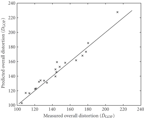
Measured overall distortion ( ˜DGOP)
Figure 11: For each possible bit rate assignment, the cross (×)
shows the measured distortion ˜DGOPhorizontally and the predicted
distortionDGOPvertically. The line represents the points where the
measurements would match the predicted distortion.
To validate our model, we will compare the measure-ments of the overall distortion of a GOP with the predic-tions made with our model (25). We used the JPEG2000 en-coder/decoder as our video coder (Figure 2), and encoded the Carphone sequence. In the first experiment, a GOP of ten frames was encoded with different bit rate allocations. No residual channel errors are introduced. In the second ex-periment, random bit errors were introduced in the encoded bitstream to simulate an error prone channel. In the third experiment, we addressed the issue of finding the optimal GOP length. In all these experiments, we used the models (25) and the parameters we have obtained inSection 4for the first ten frames of Carphone. In the last experiment, we used our models to optimize the settings for a whole sequence. We compare optimizing the settings with our models and with two other simple rate allocations. Furthermore, we have in-vestigated the gain that can be achieved if the RD curves are known for each individual frame instead of the average RD curves.
5.1. Optimal rate allocation
In this experiment, no residual channel errors were present (BER =0) and the average bit rate available for each frame was 0.2 bpp. To each frame, we assigned bit rates varying from 0.1, 0.2, 0.3 to 1.1 bpp, while keeping the average bit rate constant at 0.2 bpp. The GOP length was set to 10. The total number of possible bit rate allocations with these constraints is 92378.
A GOP of ten frames was encoded with each of these bit rate allocations. We then measured the overall distortion de-noted by ˜DGOP and compared that with the predicted dis-tortion DGOP (using (4), (10), and (15)). Figure 11shows the results. All points were plotted with the measured dis-tortion ˜DGOPon the horizontal axis. The vertical axis shows the predicted distortionDGOP. The straight line corresponds
Measured overall distortion ( ˜DGOP)
100 120 140 160 180 200 220 240
P
Figure12: Selection of 20 bit rate assignments when BER=32·
10−6. For each case the cross (×) shows the measured distortion
˜
DGOPhorizontally and the predicted distortionDGOPvertically. The
solid line represents the points where the predicted distortion and the measured distortion would match.
to the points where the prediction matches the measured val-ues. Points under this line underestimate the measured over-all distortion and the points above the line overestimate the measured overall distortion. The region we are interested in is located in the lower left area where the bottom-most point represents the bit rate allocation that minimizes our model, DGOP(25). The cloud shape gives good insight in the predic-tive strength of the model since the points are never far off the corresponding measured distortion.
As we can see inFigure 11, the predicted distortion and the measured distortion correspond well over the whole range of bit rate allocations. Note that although it is not pos-sible with these proposed behavior models to find the exact values of ri yielding the minimal measured distortion (we only know the exact distortion after encoding and decod-ing), the predicted minimal distortion is close to the mea-sured minimum distortion. We use the following metrics to express the performance of the model: the relative error
ε1=E
and the standard deviation of the relative error:
ε2=std
For this experiment,ε1 = 3.2%, which means that we slightly overestimated all distortions; ε2 = 5.7%, which means that on average our predictions were within 3.2−5.7= −2.5% and 3.2 + 5.7=8.9% around the measured values.
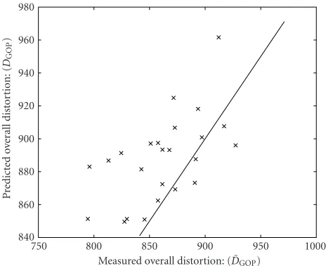
Measured overall distortion: ( ˜DGOP)
750 800 850 900 950 1000
P
Figure13: Selection of 20 bit rate assignments when BER=1024·
10−6. For each case, the cross (×) shows the measured distortion
˜
DGOPhorizontally and the predicted distortionDGOPvertically. The
solid line represents the points where the predicted distortion and the measured distortion would match.
5.2. Optimal rate allocation for a channel
with residual errors
When residual channel errors were introduced, the same ex-periment yielded different results at different runs because of the randomness of bit errors. Therefore, for each rate alloca-tion, the coding should be done at least a thousand times and the measured distortion values should be averaged. Analyz-ing each bit allocation with such accuracy is very demandAnalyz-ing in terms of computing time, therefore, we selected twenty cases uniformly distributed from the 92378 rate allocations to gain sufficient insight in the predictive power of the be-havior models.
For this experiment, we chose BER=32·10−6.Figure 12 shows the measured average distortion ˜DGOP and the pre-dicted distortionDGOPfor the 10-frame case. Now, the rel-ative error isε1=2.0% andε2=3.7%.
Note that in these simulations, we did not use any special settings of a specific video coder and we used no error con-cealment techniques other than the standard JPEG2000 error resilience. Because of the combination of wavelet transforms and progressive bit plane coding in JPEG2000, in most cases the bit errors only caused minor distortions in the higher spatial frequencies. However, sometimes a lower spatial fre-quency coefficient was destroyed yielding a higher distortion. Any individual random distortion can differ greatly from the predicted one. Because large distortions are less likely to occur than small distortions, our model gives a boundary on the resulting distortion. We measured that for 88.0% of the cases, the measured distortion was lower than the predicted value.
We then changed our BER to 1024·10−6.Figure 13shows the measured and the predicted distortions. For this high BER, the relative performance metrics were still good,ε1 =
0.31% andε2 = 3.6%. Note that these relative metrics are similar to the case without channel errors. This means that on the average, although the channel-error distortion is hard to predict, our model is still able to make good predictions of the average distortion even under error prone conditions. Apparently, the averageDepart of the total distortion is very predictable, this is probably due to the good error resilience of the JPEG2000 encoder we used.
5.3. Selection of the optimal GOP length
In the previous experiments, the optimal bit rate allocation was selected for each frame. This experiment deals with se-lecting the optimal GOP lengthN. The same constraints were used as in the previous experiment, but now the GOP length varied from 1 to 10.
Figure 14shows for each GOP length from 1 to 10 the bit rate allocations for BER = 0. Observe that the average bit rate of 0.2 bpp per frame is spread out over each frame in the GOP to obtain a minimal overall distortionDGOP. The last case (N=10) corresponds to the bottom-most point in Figure 11.
Figure 15 shows the predicted overall distortion DGOP and measured overall distortion ˜DGOP for each of these bit rate allocations. Following our criterion (5) and (6), the op-timal GOP length isN =8. Since interframes are used, we expect that using larger GOPs gives lower distortions. This is generally true, but in these experiments we did not cover the whole solution space since we used increments of 0.1 bpp for the bit rates. With this limited resolution, we may find suboptimal solutions.
Figure 16shows the result of a simulation whereN var-ied from 1 to 15. In this simulation we only used our models to predict the distortion; the corresponding measurements were not carried out due to computational limitations (there are 600 000 combinations of rate allocations when bit rates ri ∈ {0.1, 0.2,. . ., 1.6}are used). The distortions were again minimized with an average bit rate constraint of 0.2 bpp. The points correspond to the minimum achievable distor-tion DGOP at each GOP length. We see that forN > 6, the average distortion did not substantially decrease anymore, so larger GOP lengths would not improve the quality greatly. Figure 16also shows the results of the simulations for BER= {32·10−6, 256·10−6, 512·10−6}. Note that at some point, the accumulated channel-induced distortion becomes higher than the gain we obtain from adding another interframe. At this point, the internal controller should decide to encode a new intraframe to stop the error propagation.
5.4. Optimal rate allocation for whole sequences
In this experiment, we used our models and our optimiza-tion criterion to optimize the settings for the whole sequence of Carphone.
We have compared the measured distortion with two other simple rate allocation methods.
2 4 6 8 10 0
0.2 0.4 0.6
2 4 6 8 10 0
0.2 0.4 0.6
2 4 6 8 10 0
0.2 0.4 0.6
2 4 6 8 10 0
0.2 0.4 0.6
2 4 6 8 10 0
0.2 0.4 0.6
2 4 6 8 10 0
0.2 0.4 0.6
2 4 6 8 10 0
0.2 0.4 0.6
2 4 6 8 10 0
0.2 0.4 0.6
Figure14: Bit rate allocations for BER=0. Every plot corresponds to a GOP length running fromN=1 to 10. Within each plot, for each
frame, the bit rate allocation that minimizesDGOPis shown and the average bit rate ofris 0.2 bpp.
GOP lengths:N(frames)
1 2 3 4 5 6 7 8 9 10
M
inimiz
ed
dist
o
rt
ion
(
DGOP
)
60 80 100 120 140 160 180 200 220
Figure15: Minimized distortionDGOP(—) and ˜DGOP(×) for GOP
lengths between 1 and 10 and for an average bit rate ofr=0.2 bpp.
constraints thatNmax =10 and the average bit rate is 0.2.
(2) Every frame has the same fixed bit rater = 0.2. The GOP length is obtained using our models and opti-mization criterion.
(3) Every frame has the same fixed bit rater = 0.2. The GOP length has a fixed value of 10.
GOP lengths:N(frames)
0 5 10 15
M
inimiz
ed
dist
o
rt
ion
(
DGOP
)
0 100 200 300 400 500 600
BER=0 BER=32E−6
BER=256E−6 BER=512E−6
Figure16: Minimized distortionDGOPfor GOP lengths between 1
and 15, for different BERs, and an average bitrate ofr=0.2 bpp.
These methods were applied to the Carphone and the Susie sequences for BER = 0, BER = 128·10−6, and BER =
Table1: Comparison between different rate allocation methods.
Case Method Distortion
1 2 3
Carphone BER=0 76.6 91.1 90.6
Carphone BER=128·10−6 136.8 161.3 161.1
Carphone BER=512·10−6 397.7 408.4 410.4
Susie BER=0 28.6 28.9 28.9
Susie BER=128·10−6 47.4 49.6 59.5
Susie BER=512·10−6 116.4 117.1 151.2
method (3) perform more or less the same. When bit errors are introduced, method (1) still outperforms the other two. For Susie, method (1) also outperforms the other two. When bit errors are present, method (2) (just adapting the GOP length) greatly outperforms method (3). We conclude that the performance of our method depends heavily on whether the characteristics of the source are changing over time or not. It seems that either optimizing the GOP length or the bit rates decreases the distortion as opposed to method (3).
Finally, we have investigated whether using RD param-eters for each individual frame instead of average RD pa-rameters, indeed gives a significant increase of the perfor-mance. We compared the case where for each individual frame the corresponding RD function is used for optimiza-tion (case 1), and the case where one average RD funcoptimiza-tion is used for the whole sequence (case 2). For Carphone, we measured the following: for case 1, the average distortion D = 76.5, for case 2, D = 91.0. This means that signifi-cant gains can be expected when the RD curves are known for each frame. Of course in practice this is not possible. On the other hand, since consecutive frames look alike, we be-lieve that an adaptive method to obtain the RD curves from previous frames could give significant gains. For Susie we have similar results. For case 1, D = 28.6, and for case 2, D=47.9.
6. DISCUSSION
In this paper, we introduced a behavior model that predicts the overall distortion of a group of pictures. It incorporates the structure and prediction scheme of most video coders to predict the overall distortion on a frame-per-frame ba-sis. Furthermore, the model corrects for statistical dependen-cies between successive frames. Finally, our model provides a way to predict the channel-induced distortion when residual channel errors are present in the transmitted bit steam.
Although the deviation of the model predicted distortion from the measured distortion can become substantial, with this model we can still compare different settings and select one likely to cause the smallest distortion.
Our models are designed to closely follow the behavior of the encoder, given the characteristics of the video data, and to make an accurate prediction of the distortion for each frame. These predictions are made before the actual encoding of the
entire group of pictures. To predict the average distortion, we need to know the variance of each frame and the variance of the frame difference of the consecutive original frames. We also need two parameterized rate distortion curves and six other parameters (κ,α,β,LI,LP, andλ).
In our experiments—some of which were shown in this paper—we noticed that these parameters do not change greatly between consecutive group of pictures, therefore they can be predicted recursively from the previous frames that have already been encoded. On the other hand, we have shown that significant gains can be expected when the rate distortion parameters are obtained adaptively and no aver-age rate distortion curves are used. The factorsκ,α,β,LI,LP, andλdo not depend greatly on the source data, but rather on the coder design, and thus may be fixed for a given video encoder.
After obtaining the frame differences, the distortion can be predicted before the actual encoding takes place. This makes the model suitable for rate control and constant bit rate coding as well as for quality of service controlled coders. Although this paper focused on rate allocation of en-tire frames rather than on macroblocks, all models can be generalized for use at the macroblock level.
REFERENCES
[1] J. L. Mitchell, W. B. Pennebaker, C. E. Fogg, and D. J. LeGall, MPEG Video Compression Standard, International Thompson Publishing, London, UK, 1996.
[2] G. C ˆot´e, S. Shirani, and F. Kossentini, “Optimal mode selec-tion and synchronizaselec-tion for robust video communicaselec-tions over error prone networks,”IEEE Journal on Selected Areas in Communications, vol. 18, no. 6, pp. 952–968, 2000.
[3] G. M. Davis and J. M. Danskin, “Joint source and channel coding for image transmission over lossy packet networks,” in Proc. SPIE Conference on Wavelet Applications of Digital Image Processing XIX, vol. 2847, pp. 376–387, Denver, USA, 1996. [4] M. Brystrom and J. W. Modestino, “Combined source
chan-nel coding for transmission of video over a slow-fading rician channel,” inProc. International Conference on Image Process-ing, vol. 2, pp. 147–151, Chicago, Ill, 1998.
[5] K. Stuhlm¨uller, N. F¨arber, and B. Girod, “Analysis of video transmission over lossy channels,” IEEE Journal on Selected Areas in Communications, vol. 18, no. 6, pp. 1012–1032, 2000. [6] A. van der Schaaf and R. L. Lagendijk, “Independence of source and channel coding for progressive image and video data in mobile communications,” inProc. Visual Communi-cations and Image Processing, vol. 4067, pp. 187–197, Perth, Australia, June 2000.
[7] H. van Dijk, K. Langendoen, and H. Sips, “ARC: a bottom-up approach to negotiated QoS,” inProc. 3rd IEEE Workshop on Mobile Computing Systems and Applications, pp. 128–137, Monterey, Calif, USA, December 2000.
[8] Y. S. Chan and J. W. Modestino, “Transport of scalable video over CDMA wireless networks: a joint source coding and power control approach,” inProc. International Conference on Image Processing, vol. 2, pp. 973–976, Thessaloniki, Greece, October 2001.
[10] J. R. Taal, K. Langendoen, A. van der Schaaf, H. W. van Dijk, and R. L. Lagendijk, “Adaptive end-to-end optimization of mobile video streaming using QoS negotiation,” inProc. In-ternational Symposium on Circuits and Systems, vol. 1, pp. 53– 56, Scottsdale, Ariz, USA, May 2002.
[11] K. Ramchandran, A. Ortega, and M. Vetterli, “Bit allocation for dependent quantization with applications to multiresolu-tion and MPEG video coders,” IEEE Trans. Image Processing, vol. 3, no. 5, pp. 533–545, 1994.
[12] M. Boliek et al., “Jpeg 2000 part 1 final committee draft, ver-sion 1.0,” Tech. Rep., JPEG, 2002.
[13] G. Reyes, A. R. Reibman, and S. F. Chang, “A corruption model for motion compensated video subjected to bit errors,” inProc. Packet Video Workshop ’99, NY, USA, April 1999. [14] J. G. Kim, J. Kim, and C. C. J. Kuo, “Corruption model of
loss propagation for relative prioritized packet video,” inProc. SPIE Applications of Digital Image Processing XXIII, vol. 4115, pp. 214–224, San Diego, July 2000.
Jacco R. Taal received his M.S. degree in Electrical Engineering from Delft University of Technology, Delft, The Netherlands, in 2001. At present he is pursuing his Ph.D. degree at the same university. His research interests include real-time video compres-sion for wireless communications and peer-to-peer systems. Currently he is doing re-search on video transmissions for peer-to-peer communications and ad hoc networks.
Zhibo Chen received his B.S., M.S., and Ph.D. degrees from the Department of Electrical Engineering, Tsinghua University, Beijing, China, in 1998, 2000, and 2003, re-spectively. He is currently with Sony Re-search Center, Tokyo. His reRe-search interests include video coding theory and algorithm and video communication over networks.
Yun He received the B.S. degree in signal processing from Harbin Shipbuilding Insti-tute, Harbin, China, in 1982, the M.S. de-gree in ultrasonic signal processing from Shanghai Jiaotong University, Shanghai, China in 1984, and the Ph.D. degree in im-age processing from Liege University, Liege, Belgium, in 1989. She is currently an Asso-ciate Professor at Tsinghua University, Bei-jing, China. She serves as a Senior Member
in IEEE, Technical Committee Member of Visual Signal Processing and Communications in IEEE CAS Society, Picture Coding Sym-posium Steering Committee Member, as a Program Committee Member in SPIE Conference of Visual Communications and Im-age Processing (2000-2001). Her research interests include picture coding theory and methodology, picture coding algorithm software and hardware complexity analysis, video codec VLSI structure, and multiview and 3D picture coding.
R. (Inald) L. Lagendijk received his M.S. and Ph.D. degrees in electrical engineer-ing from Delft University of Technology in 1985 and 1990, respectively. Since 1999, he has been a Full Professor in the Informa-tion and CommunicaInforma-tion Theory Group of Delft University of Technology. Prof. La-gendijk was a visiting scientist at Eastman Kodak Research (Rochester, NY) in 1991 and a Visiting Professor at Microsoft