FPGA Based Efficient Median Filter
Implementation Using Xilinx System
Generator
Siddarth Sharma1, K. Pritamdas2
P.G. Student, Department of Electronics and Communication Engineering, NIT Manipur, Imphal, Manipur, India1 Assistant Professor, Department of Electronics and Communication Engineering, NIT Manipur, Imphal, Manipur,
India2
ABSTRACT: Digital Images are an important medium to convey visual information. However, digital images are often corrupted by noise. In this paper, an efficient implementation scheme for median filter is proposed, which is used to remove impulse noise from images. So, the resultant image of the filter is the image with reduced impulse noise. Impulse noise reduction is done using the application of the median filter to the corrupted image by sorting the pixels using a 3x3 window and selecting the median of the window.
KEYWORDS: Impulse Noise, embedded image processing, Xilinx system generator (XSG), FPGA, Simulink, ASIC. I. INTRODUCTION
Images are an important way of conveying visual information. Digital images tend to get corrupted by noise due to the image sensors, interference in transmission medium or due to atmospheric disturbances. Impulse Noise is the most common noise that occurs in digital images [1]. The most important property about image is that, they can be treated as stationary, and a sliding window can be used which slides over the entire image, successfully placing all the pixels of the image in it[14]. The function of the sliding window is just placement of the pixels in it;it’s the function of the filter which processes the pixels in the sliding window.
Embedded Image Processing are the best approach towards ASIC (Application Specific Integrated Circuits) as they pave the way for Hardware which can take the input as image do some processing and give the output back as an image, letting the processing to be done by a powerful microprocessor or reconfigurable hardware like FPGA[7,8].
A brief introduction to impulse noise has been given in Section II, describing how it changes the pixels of the image and the noise model for it. In section III, IV and V, the Xilinx system generator design flow has been discussed along the pre-processing and post-processing tasks done to images so that they can be processed by the System Generator blocks. In section V, the performance evaluation of the proposed method is done, and the results are discussed.
II. IMPULSENOISE
Corruption of digital images by impulse noise [14] is very common. It is independent as well as uncorrelated to the image pixels and occurs randomly over the image. Unlike Gaussian noise, impulse noise only corrupts a subset of the image pixels, the rest will be uncorrupted. There are two types of impulse noises: salt and pepper noise and random-valued impulse noise. This paper mainly focuses on removal of salt and pepper noise from images. In salt and pepper noise the noisy pixels attain either a high value (grey level 255) or low value (grey level 0), hence this noise is termed as salt and pepper, giving the appearance of black and white spots on the images. If γ is the corruption probability,
0 or 255 with probability γ
x(i,j) = (1)
o(i,j) with probability 1- γ
wherex(i,j) represents the noisy image pixel, where i,j are the spatial coordinates, o(i,j) represents the original image.
III.XILINXSYSTEMGENERATORDESIGNFLOW
Fig 1 System Generator Design Flow
Fig 1 shows the system generator design flow [11,12]. First, the proposed algorithm is designed using MATLAB Simulink. Then the system generator token invokes the respective IP cores for the target FPGA, in the next step it designs the RTL schematic for the proposed method, and it is ready for implementation in the target hardware.
IV.IMAGEPRE-PROCESSING
Fig 2. Window Generator used for imitating the 3x3 window.
The “To Frame “ and “Unbuffer” blocks are used to send the elements of the window one by one for each clock cycle. The pixels are ready to be sent to the system generator blocks.
V. MEDIANFILTERIMPLEMENTATIONINSYSTEMGENERATOR
The Median of nine pixels can be calculated using the traditional sorting method, which is done by arranging the pixels in ascending or descending order and picking the middle value as the median. Or it can be done by calculating the distance between the pixels using the distance norms as discussed in [13]. The pixel with the minimum distance to all the pixels is the median.
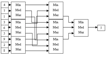
In the proposed method, the median is calculated in a different fashion. It is done be sub-dividing the nine pixels into three parts and with each parts containing three pixels. The minimum, median and maximum is calculated for each part. And again, a maximum from the minimums, a minimum from the maximums and a median from the medians is chosen. And from these three, the median is calculated which will be the final median of the nine pixels. Fig 3 shows the block diagram for calculation of median using the method discussed in [4,10].
Fig. 3 Median calculation using the proposed method.
floating point or a viewable format by MATLAB [2, 3]. Fig 4 shows the “Gateway In” and “Gateway Out” block used for defining the FPGA based design.
(a)Gateway In (b) Gateway Out
Fig. 4 (a) Gateway In and (b) Gateway Out, used for defining the boundary of the FPGA based design
After the image pre-processing portion is complete, the pixels are ready for calculation and interaction with the FPGA through the Gateway blocks shown in Fig 4. Now, the actual design of the proposed method for median calculation is shown in Fig 5.
Fig.5 System Generator block for Median calculation
VI.IMAGEPOSTPROCESSING
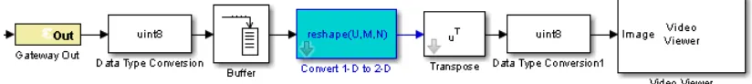
Since the output of the system will be floating point, it needs to be converted to unsigned integer of 8-bit, because data type of image pixels are unsigned integer taking up 8 bits of data, the output pixel will be an individual pixel, that need to be stored in a buffer equal to the size of the image [9] and then converted back to 2D data using the reshape block as shown in fig 6. The image is now ready for viewing in a video viewer block
VII. RESULTSANDDISCUSSIONS
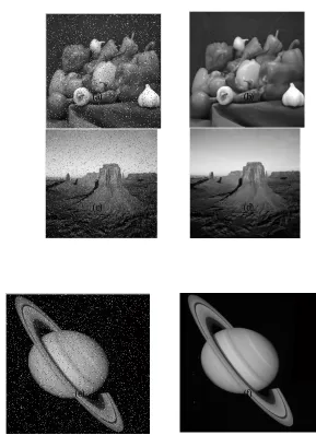
After the blocks are designed. The target hardware used for the design is Spartan6xc6slx9-3csg324, the images used for testing the design are Peppers image (256x256), desert image (512x512) and Saturn image (512x512) are shown in Fig 7.
(a) (b)
(c) (d)
(e) (f)
Fig 7. (a) Noisy peppers image, (b) filtered peppers image, (c) Noisy desert image, (d) Filtered desert image, (e) Noisy Saturn image, (f) Filtered Saturn image
Design Comparators Adders/Subtracters
Sorting Method 36 -
Distance Calculation Method
8 135
Proposed Method 12 -
Fig 8. Comparison between the proposed method and the traditional methods.
Slice Logic Utilization Used Available Utilization
1. Number of slice registers
0 11,440 0%
2. Number of slice LUTs
397 5,720 6%
3. Number of occupied slices
164 1,430 11%
4. Number of bonded IOBs
80 200 40%
Fig. 9 Device Utilization Summary
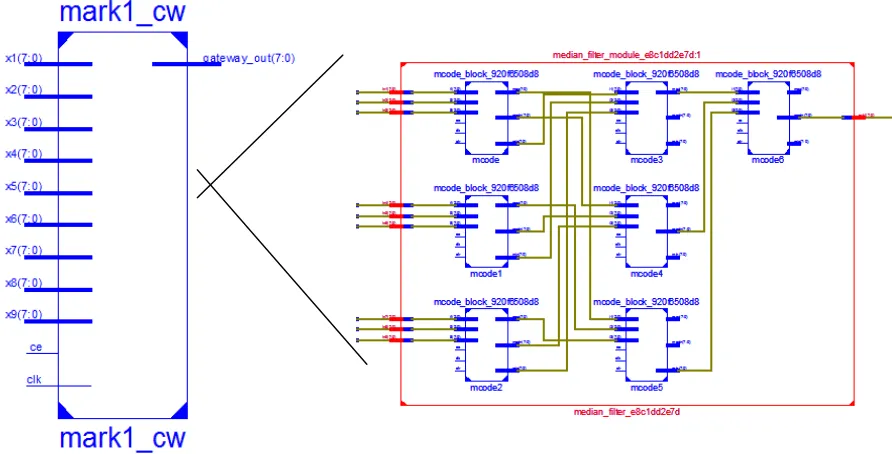
Fig.10 RTL Schematic of the proposed method and its zoomed view
VIII. CONCLUSION
From the results of the proposed method and the resources utilized by it, it can be concluded that it can serve as a better candidate for removing impulse noise from images efficiently, and can be further extended towards removal of impulse noise from video frames in the fields of video processing, it will have potential applications in the fields of satellite imaging, bio-medical imaging, digital image sensors etc
REFERENCES
[1] A. K. Jain, “Fundamentals of Digital Image Processing” , Prentice Hall of India, First Edition,1989
[2] Ankita Gupta, Himanshu Vaishnav and Himanshu Garg, “Image Processing using Xilinx System Generator (XSG) in FPGA,” International Journal of Research and Scientific Innovation, vol 2, 2015
[3] A. T. Moreo, P. N. Lorente, F. S. Valles, J. S. Muro and C.F. Andres, Experiences on developing computer vision hardware algorithms using Xilinx system generator” Microprocessors and Microsystems, Vol. 29, pp.411 -419 November 2005
[4] Chakrabarti, C. and Wang, L.Y. (1994) Novel sorting network-based architectures for rank order filters. IEEE Transactions on VLSI Systems, 2 (4), 502–507
[5] Haidi Ibrahim, Kuo Chue Neo, Sin Hoong Teoh, Theam Foo Ng, Derek Chan Juinn Chieh, and Fakhuruddin Nik Hassan, “ Impulse Noise Model and Its Variations”, International Journal of Computer and Electrical Engineering, Vol 4(5), (2012).
[6] Introduction to Xilinx System Generator Bitweenie community ( http://in.mathworks.com/solutions/fpga-design/simulink-with-xilinx-system-generator-for-dsp.html)
[7] I. Kuon, and J. Rose, "Measuring the gap between FPGAs and ASICs," Computer-Aided Design of Integrated Circuits and Systems, IEEE Transactions on 26, no. 2 (2007): 203-215.
[8] U. Meyer-Baese, “Digital signal processing with field programmable gate arrays,” Vol. 65. Heidelberg: Springer, 2007
[9] V. Elamaran, Angam Praveen,, “FPGA implementation of Spatial image filters using Xilinx System Generator,” Procedia Engineering, International Conference on Modeling, Optimization and Computing, pp 2244-2249, (2012)
[10] Waltz, F.M. (1994c) “Separated-kernel image processing using finite-state machines (SKIPSM)”, in Machine Vision Applications, Architectures, and Systems Integration III, Boston, Massachusetts, USA (31 October–2 November, 1994), vol. 2347, SPIE, pp. 386–395 [11] Xilinx System Generator user guide.
[12] Xilinx System Generator website (http://www.xilinx.com/video/hardware/getting-started-with-system-generator.html.html).
[13] R.M. Nosovsky, “Choice, similarity and the context theory of classification,” Journal of Experimental Psychology: Learning, Memory, and Cognition, vol. 10, no. 1,pp. 104–114, January 1984.