Numerical Simulation of Shear Wall Nonlinear Behavior Subjected to
Lateral Loads
Somnath Jha1, A.D. Roshan1, Kapilesh Bhargava2, L.R. Bishnoi3 and Sekhar Basu4
1Scientific Officer, Siting and Structural Engineering Division, Atomic Energy Regulatory Board, Anushaktinagar, Mumbai 400094 India ([email protected], [email protected]).
2Assistant General Manager, Civil Engineering Directorate, NRPSD&SA, Nuclear Recycle Board, Bhabha Atomic Research Centre, Anushaktinagar, Mumbai 400094, India. ([email protected];
3Head, Siting and Structural Engineering Division, Atomic Energy Regulatory Board, Anushaktinagar, Mumbai 400094 India.
4Director, Bhabha Atomic Research Centre, Trombay, Mumbai 400085, India.
ABSTRACT
Quantification of seismic margin to cater to the extreme events beyond design basis earthquake level of NPP structures could help in assuring safety in case of such highly unlikely events. In NPPs, lateral load bearing members mainly consist of shear walls and in order to assess the seismic margin accurately, it is necessary to understand and appropriately capture their lateral behavior.
Finite element method has been the mainstay of assessment of nonlinear behavior of shear walls. Barring analysis of simple configurations of shear wall cores in tall buildings, its application to shear wall structures of complex configuration such as in an NPP is still emerging due to constraints in application of macro models of shear walls for such configurations, requirement of appropriate micro material models and inadequacies in numerical tools to cater to large amount of computational requirements.
Validation and benchmarking of numerical tools used assumes significance in this context. The current work evaluates capabilities of finite element software Abaqus to simulate inelastic lateral response of six different types of shear walls with aspects ratios ranging from ½ to 2. Input parameters that play key role in lateral load response are identified based on sensitivity analysis and a consistent approach is suggested for non-linear lateral response of shear walls. The analyses based on the suggested approach are found to provide good estimates of monotonic lateral load behavior including ultimate capacity. Limitations of extending this approach to cyclic loading are also identified.
INTRODUCTION
Recent episodes of exceedance of design basis seismic events at NPP sites of Fukushima daichii in 2011 and Kasiwazaki Kariwa in 2007 has initiated a debate on performance assessment of NPP structures for „beyond design basis seismic events‟. The structure that houses different components important to safety should not reach its limit state, be it a functional one or structural one. In order to ensure safety under extreme seismic event, in-depth investigation is needed to identify vulnerable area and strengthen them appropriately. This exercise is an attempt to quantify seismic margin of concrete shear walls used in building structures.
slender shear walls, its applicability to squat shear wall is limited owing to inadequacy in capturing shear or coupled flexure-shear failure.
Finite element method has been the mainstay of assessment of nonlinear behavior of Reinforced Concrete (RC) structures. Pushover analysis and nonlinear time history analysis are the possible approaches that can be used for seismic performance assessment. Barring analysis of simple frame type of structures where application of pushover methods for performance assessment has reached enough level of maturity, its application to shear wall structures with complex configuration such as in an NPP is still emerging. This is due to constraints in application of macro models of shear walls for such configurations, requirement of appropriate micro material models, and inadequacies of specialized numerical tools to cater to the computational requirements of such complex structures.
In general, a simple moment-rotation response, Park and Paulay (1975), of individual components is sufficient for capturing the global behavior of frame structures consisting of beams and columns. However, this is not the case with shear walls exhibiting coupled shear-flexure response. General purpose finite element software Abaqus, Dassaults Systemes SIMULIA-2011, has capabilities of solving nonlinear problems with complex configurations including integrated modeling of multiple types of elements capturing entire spectrum of structural configurations inside an NPP. In this respect validation and benchmarking of analysis models in this software assume particular significance. However, studies, Palermo and Vecchio (2002), Kwan and He (2001) etc., that cover benchmarking, adopt very limited number of cases and offers only limited scope of validation. The current paper brings out a consistent approach that can be used for simulating the nonlinear response of shear wall with low aspect ratios.
FINITE ELEMENT MODELING OF SHEAR WALLS
A realistic and practical modeling and prediction of inelastic response of RC shear wall structures under lateral loading requires analytical models capable of reproducing the nonlinear response of each structural component with reasonable accuracy and simple enough to allow computationally economic solutions. Nonlinear finite element analysis is being increasingly used to predict inelastic response of RC shear wall structures, Palermo and Vecchio (2002), Kwan and He (2001) etc. Despite extensive experimental and analytical research on the behavior of RC wall structures subjected to lateral loads, current analytical approach of material modeling is not simple enough to solve problem of NPP shear wall structures that have complex configurations. Researchers of university of Toronto developed a finite element package VecTor2, incorporating various complexities of material modeling to predict the behavior of shear wall under lateral loads but it is of limited use for carrying out study on experimentally tested specimens.
Simple material models are often computationally efficient but have limited accuracy of behavior predictions in nonlinear regime and complex models could land in convergence issues. A proper material model for nonlinear finite element analysis should be capable of representing both elastic and plastic behavior of concrete in compression and tension and should also be simple enough to be used for larger problems. Simulation of behavior under tension should include tension softening, tension stiffening, and local bond effects in reinforced concrete elements. Therefore, development of a finite element (FE) model appropriate for seismic performance study of shear walls requires extensive studies towards validation of available material models in the FE packages. The subsequent sections discuss evaluation of material models available in Abaqus and selection of appropriate model, its calibration and validation exercises.
SELECTION OF CONCRETE MATERIAL MODEL
provide appropriate solutions. The model assumes elastic behavior of concrete under compression regime, leading to its limited use where section is under mixed or compressive stress regime.
The concrete smeared crack model is capable of capturing nonlinear behavior of concrete under compression as well as tension. Behavior of concrete under biaxial state of stress can also be included by defining biaxial strength envelope. Degradation of elasticity under load reversal is not incorporated, thus limiting its use under cyclic loading. Studies by authors have indicated that use of this model for RC shear walls possesses challenges in convergence of the solution algorithm when material strain reaches softening regime of concrete. Absence of viscoplastic regularization of constitutive equations used within this model, which could provide smooth solution in nonlinear range, limits use of this model.
Concrete damage plasticity (CDP) model addresses some of the drawbacks of other models and it is capable of capturing behavior of concrete under multiaxial state of stress. This model also has viscoplastic regularization scheme to overcome the difficulties in achieving convergence, which could be a valuable tool in nonlinear analysis. This is thus a candidate model for involving monotonic and cyclic loading regime.
CONCRETE DAMAGE PLASTICITY MODEL
The CDP model uses the concept of isotropic damaged elasticity in combination with isotropic tensile and compressive plasticity to represent the inelastic behavior of concrete. It is based on the assumption that the main failure mechanisms are tensile cracking and compressive crushing of the concrete material. Uniaxial stress-strain response of concrete under compression and tension can be specified in tabular form in this model therefore providing flexibility to use any analytical models for stress block definition.
To define failure surface under multiaxial state of stress and plastic flow upon yielding, additional input parameters are required. Default values of these parameters are given in Abaqus user manual, Abaqus 6.10 documentation (2010). The evaluation carried out as a part of current exercise indicated that the lateral behavior of RC shear walls in nonlinear regime is highly dependent on some of these parameters. In addition, use of default values resulted in difficulties in obtaining converged solution. Considering the above constraints, combined calibration-sensitivity analyses were performed on these parameters to arrive at values appropriate for analysis of RC shear walls.
In addition, variable that depicts damage in CDP model needs to be defined under compression and tension regime. In some sense, these damage variables represent reduction in load carrying area due to cracks and damage in concrete. Effective stress is calculated based on specified damage variable. There are no default values suggested for these damage parameters.
STUDY ON INPUT PARAMETERS IN CDP MODEL
Input parameters are needed to represent the elastic and plastic behavior of concrete under uniaxial and multiaxial state of stress. While, simple stress-strain curves under tension and compression are sufficient to represent uniaxial behavior, depiction of multiaxial behavior needs definition of yield surface, failure surface and flow rule. Abaqus provides facility to define the failure surface of concrete under multiaxial state of stress. The CDP model uses the yield function of Lubliner et al. (1989), with the modifications proposed by Lee and Fenves (1998) and it assumes non-associated potential plastic flow with Drucker-Prager hyperbolic function as flow potential. Upcoming sections explain input parameters of CDP model and their best suited values/models for RC shear walls.
Models for Concrete under Uniaxial Compression
per study carried out by Shamim (1982), Modified Kent and Park model, (1982) gives more realistic behavior of unconfined concrete and concrete confined by rectangular hoops. This model was chosen to represent uniaxial compression of concrete in the current work.
Tension Stiffening Model
In order to simulate the complete tensile behavior of reinforced concrete in Abaqus, a post cracking stress-strain relationship for concrete is used, which accounts for tension stiffening, strain-softening, and reinforcement (RF) interaction with concrete.
Wahalathantri et al. (2011) provided a tension stiffening model that was a modification over Nayal and Rasheeds (2006) model for use of the same in finite element packages. The application of this model in CDP has reportedly provided satisfactory results in the study carried out by them, hence this model is used to provide tension stiffening of concrete in the current work.
Damage Variable under Compression (dc)
As observed experimentally, Karsan and Jirsa (1969), the residual strain upon unloading is not equal to the inelastic strain. Abaqus calculates residual plastic strain depending upon defined damage variable. Hence, definition of damage variable is crucial and needs the knowledge of plastic residual strain upon unloading from a particular point on stress-strain curve. There are a number of models based on experimental observations, Karsan and Jirsa (1969), Bhan and Hsu (1998), Palermo and Vecchio (2003), etc. available for the calculation of residual plastic strain upon unloading in compression. Palermo and Vecchio (2003) combined all experimental data together and formulated an equation which contains information from all the tests performed earlier and hence is used in the current work.
(1)
Knowing the plastic residual strain, dc can be evaluated as:
(2)
Where, E is modulus of elasticity of concrete, 𝜎𝑐 is stress at unloading, and 𝜀𝑐𝑖𝑛 is inelastic strain,
𝜀𝑐 is strain at unloading, 𝜀𝑝 is strain at peak stress, and 𝜀𝑐𝑝 is residual plastic strain.
This expression for 𝑑𝑐 is applicable post linear elastic region of stress-strain curve. In linear elastic region 𝑑𝑐 is zero.
Damage Variable under Tension (dt)
Similar to compression, residual plastic strain also occurs while concrete is unloaded from tension regime. This residual plastic strain is a symbolic representation of damaged elasticity. Abaqus provides facility to incorporate damage variable in tension as a function of cracking strain which in turn is used for calculation of plastic strain upon unloading. Compared to compression, less number of empirical models are available for calculation of residual plastic strain in tension due to difficulties in performing experiments in tension regime. In the present work plastic strain offset model of Palermo and Vecchio (2003) is used, which is a formulation based on collection of experimental data of various researchers.
(3) 𝜀𝑐𝑝 = 𝜀𝑐− 𝜀𝑝 0.868 𝜀𝑐
𝜀𝑝 − 0.166
𝜀𝑐 𝜀𝑝
2
𝑑𝑐 = 1
1 + 𝜎𝑐
𝐸 𝜀𝑐𝑖𝑛 − 𝜀𝑐𝑝
dt is calculated with the use of cracking and plastic strain as:
(4)
Where, 𝜎𝑡 is unloading stress, 𝜀𝑡𝑐𝑘 is cracking strain at unloading, 𝜀
𝑡𝑝 is residual plastic strain and
𝜀1𝑡 is unloading strain.
It should be noted that in no case 𝑑𝑡 𝑎𝑛𝑑 𝑑𝑐 should be negative or decreasing with respect to
inelastic strain. As stresses in Abaqus are specified in terms of effective stress so damage variables 𝑑𝑡 𝑎𝑛𝑑 𝑑𝑐 play important role in defining strength envelope (yield and failure surface) of concrete as well the state of stress.
Biaxial To Uniaxial Yield Stress Ratio in Compression
Concrete under biaxial state of stress exhibits higher strength and it has to be accounted while deriving any material model. Ratio of equibiaxial strength to uniaxial strength ranges from 1.16 to 1.25, Kupfer et. al. (1969), the default value in Abaqus is 1.16. However, work carried out as part of this study has indicated that variation of this ratio within this range does not significantly affect the behaviour of RC shear wall. Hence default value has been used during further evaluation.
Ratio of Second Stress Invariant on Tensile and Compressive Meridian, KC
This parameter decides the shape of the failure surface on the deviatoric plane. Its value should be in between 0.5 < KC < 1.0 (shape tends to be circular as KC approaches 1.0). The default value is 0.67
which provides a bulged triangular shape of deviatoric plane which is also supported by experimental evidence, Chen W. F. (1982). Variation of this parameter within this range (0.5-1.0) is seen to be affecting the convergence of finite element algorithm but had hardly any influence in the estimated behaviour of RC shear walls. Hence default value of KC was chosen in the present work.
Dilation Angle, 𝝍
In contrast to metals, a brittle material like concrete tends to change its volume beyond its elastic limit due to cracking and slip along cracked surfaces. This change in the volume is generally called „dilation‟. The dilation characteristic of concrete drastically affects the confinement pressure activated in a reinforced concrete member. Therefore, the axial stress-strain behaviour of concrete in compression greatly depends on the dilation characteristic. An increase in the dilation leads to more confinement and eventually a stiffer stress-strain relation, Glass P. (2004). The dilation angle is one of the parameters required for the CDP model to define the plastic flow potential.
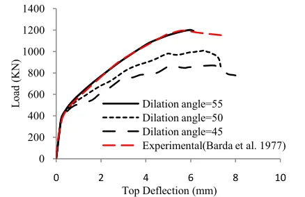
To investigate sensitivity of shear wall lateral response to the dilation angle, a series of finite element analyses were performed on a FE model of an experimental setup and results compared with the experimental data reported in literature, Barda et. al. (1977). Three different dilation angles (55, 50, and 45 degree) were used. The outcome of evaluation is shown in Figure 1. It is seen that, lateral deformation of the shear wall depends heavily on the value used for the dilation angle. As expected, the dilation angle has no impact on the response of the shear wall in the elastic regime. The stiffness of the cracked wall, however, reduces with the decrease of dilation angle. As found from comparison, a dilation angle of 55 degree is seen to be the optimal value that captures the behaviour of shear wall deformation in the lateral direction.
Similar parametric study was also carried out on FE models of five additional wall specimens of different aspect ratios and shapes, and it is found that dilation angle of 55 degree is best suited to predict the lateral load-deformation behavior of shear walls irrespective of shape and aspect ratio.
𝑑𝑡 = 1
1 + 𝜎𝑡
Figure 1. Effect of dilation angle on shear wall response
Eccentricity Parameter, e
Eccentricity parameter defines the rate at which the plastic flow function approaches the asymptote. A low value of eccentricity implies that the material has almost the same dilation angle over a wide range of confining pressure stress values. Increasing the value of e provides more curvature to the flow potential, implying that the dilation angle increases more rapidly as the confining pressure decreases. Lesser value of eccentricity may lead to convergence problems if the material is subjected to low confining pressures because of the very tight curvature of the flow potential locally where it intersects the p-axis (hydrostatic axis). The default value of eccentricity parameter used in Abaqus is 0.1. However, adoption of this value is seen to result in serious convergence issues for RC shear walls.
Jankowiak et al. (2005) carried experimental investigation to identify various parameters of concrete damage plasticity model and recommended that value of eccentricity parameter ranges from 1 to 1.5. A sensitivity analysis of this parameter within this range was conducted and result of the analyses is shown in Figure 2. It is found that, this parameter does not affect the load-deformation behaviour significantly, though there is reduction in ultimate load by 5% when lower limit of the parameter was adopted. Based on the evaluations, value of eccentricity equal to 1.5 is found to be reasonably good for prediction of ultimate load.
Figure 2. Effect of eccentricity on shear wall response
Viscosity Parameter, μ
Material models with softening behaviour and stiffness degradation could quite often lead to severe convergence difficulties in implicit analysis scheme. The CDP model provides facility for viscoplastic regularization of constitutive equations used in the material model, which causes the consistent tangent stiffness of the softening material to become positive for small increments. Use of very
0 200 400 600 800 1000 1200 1400
0 2 4 6 8 10
Lo
ad
(K
N
)
Top Deflection (mm) Dilation angle=55 Dilation angle=50 Dilation angle=45
Experimental(Barda et al. 1977)
0 200 400 600 800 1000 1200 1400
0 2 4 6 8 10
Lo
ad
(K
N
)
Top Deflection (mm)
x 0.001
e=1.5 e=1.0 e=1.25
small viscosity parameter is recommended in cases where severe nonlinearity is expected, as use of large value may provide misleading results. Default value of μused in Abaqus is 0.0. Work carried out as part of the present study indicates that a value of 5x10⁻⁴ could be used for RC shear walls to overcome convergence difficulties without sacrificing the solution accuracy. However, further increase in the value is seen to result in stiffer response of shear wall in nonlinear range.
FE ANALYSIS FOR MONOTONIC LOADS
Before application of any material model available in finite element packages to RC shear wall structures to predict its lateral response, it is first necessary to validate the numerical model used. As the aim of current exercise was evaluation of numerical models for shear walls with respect to lateral loads, a variety of configurations of experimentally tested shear wall specimens were chosen for analysis. Material input parameters of the CDP model were chosen based on the evaluation described in previous section. Finite element analyses using the set of identified input parameters were carried out on six shear wall specimens to ascertain validity and accuracy of the developed approach. The selected shear walls for the study, represented walls of different types, viz. aspect ratio, shape, reinforcement detailing, axial loading etc. (Table 1). Aspect ratio of selected wall specimens ranges from ½ to 2 and two out of six walls had flange wall as boundary elements. Stress-strain behavior of reinforcing steel is taken from corresponding literature. Details of the shear wall specimens considered in this study are given in Table 1. All the walls are modeled using 4-noded shell elements (S4R) with smeared layer of reinforcement.
Table 1: Details of shear wall specimens
Specimen
designation shape Wall Aspect ratio Axial load Ultimate drift (%) Tested by
SW14 Simple 1.1 0 1.40 Lefas et. al. (1988)
SW21 Simple 2.1 0 1.50 Lefas et. al. (1988)
SW22 Simple 2.1 0.1*shear capacity 1.00 Lefas et. al. (1988) SW23 Simple 2.1 0.2*shear capacity 1.00 Lefas et. al. (1988)
B1-1 Flanged 0.5 0 0.59 Barda et. al. (1977)
DP-1 Flanged 0.7 0.75*shear capacity 0.54 Palermo & Vecchio (2002)
RESULTS AND DISCUSSIONS
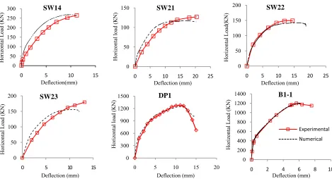
Comparison of experimental results and numerical predictions by Abaqus using the developed method is presented in Table 2. The maximum variation in prediction of ultimate strength of wall was 13% and the average variation was within 5%. The numerical prediction of key parameters like ultimate strength, ultimate drift and initiation of yielding of tensile reinforcement also showed close agreement with the experimentally observed values, average variation being 4.8%, 5.4% and 2.2% respectively (Table 2). Comparison of experimental and numerically simulated pushover curves for different specimens is shown in Figure 3.
Figure 3. Comparison of experimental and numerical pushover curves
Table 2: Comparison of numerically predicted and experimentally observed overall behaviour of walls
Specimen designation Ultimate load (KN) Top deflection(mm) Base shear at1st Yield of steel Experiment Analysis Experiment Analysis Experiment Analysis
SW14 265 266 11.21 10.0 170 171.5
SW21 127 115 20.61 19.58 80 78.6
SW22 150 143 15.30 16.0 110 108.3
SW23 180 155 13.19 12.4 120 112.5
DP1 1276.5 1272 11.07 11.0 -- 1200
B1-1 1196 1200 5.7 6.0 996 990
The work instills enough confidence that the CDP model, with the modifications as suggested in this study, could be used to predict the nonlinear behavior of shear walls subjected to monotonic loading.
FE ANALYSIS FOR CYCLIC LOADS
Based on the confidence gained on implementation of the CDP model of Abaqus with regard to lateral loads of monotonic nature, the exercise was extended to evaluation with respect to cyclic loads. A successful implementation of the same could extend the use of models for accurate predictions of performance points not only by pushover analysis but also by nonlinear time history analysis.
Modeling of response under cyclic loading using the CDP model requires definition of additional parameters viz. stiffness recovery factor under tension, wt, compression, wc, and damage parameters. Degradation of stiffness under cyclic load reversal is accounted by stiffness recovery factors and damage
0 50 100 150 200 250 300
0 5 10 15
H or iz on ta l L oa d (K N ) Deflection(mm) SW14 0 50 100 150
0 5 10 15 20 25
H or iz on ta l l oa d (K N ) Deflection (mm) SW21 0 50 100 150 200
0 5 10 15 20 25
H or iz on ta l L oa d( K N ) Deflection (mm) SW22 0 50 100 150 200
0 5 10 15
Ho riz on ta l L oa d (K N) Deflection (mm) SW23 0 300 600 900 1200 1500
0 5 10 15 20
H or iz on ta l l oa d (K N ) Deflection (mm) DP1 0 200 400 600 800 1000 1200 1400
0 2 4 6 8 10
parameters. Figure 4(a) shows hysteresis curve under cyclic loading reported by Pilakoutas and Elnashai (1995) and Figure 4(b) shows corresponding numerically simulated hysteresis curve of tested shear wall.
(a) (b)
Figure 4. (a) Hysteresis curve under cyclic loading reported by Pilakoutas and Elnashai (1995), (b) numerically simulated hysteresis curve.
The study indicated that the overall behavior in terms of ultimate load, drift at ultimate load, stiffness degradation could be predicted with reasonable accuracy but pinching in the hysteresis loop could not be captured. It is seen that the CDP model does not take into account crack-closing mechanism and shear slip along the crack, which leads to lesser energy dissipation in the form of pinching behavior. Though stiffness recovery factors take into account the cyclic degradation under load reversals through which overall global behavior can be predicted, it is required to model crack-closing, crack shear-slip, etc. for better simulations of the energy dissipation in the hysteresis loops including pinching.
SUMMARY AND CONCLUSIONS
Assessment of seismic capacity of shear wall needs derivation of its inelastic behavior subject to lateral loads. A unified approach using a set of identified parameters of material modeling with finite element software Abaqus for assessment of lateral behavior of shear walls is presented in this paper. Parametric study to identify sensitivity of input data for finite element modelling and for developing a common procedure for numerical analysis using CDP model of Abaqus revealed that the default values provided in the software are not sufficient to accurately capture the response of a RC shear wall.
Inelastic response of shear wall subjected to lateral load is found to be highly sensitive to dilation angle, 𝜓and convergence of finite element algorithm is seen to be dependent on eccentricity parameter, e. Based on the study it is concluded that, viscoplastic regularization in CDP model helps in easing the convergence difficulty in solution procedure in the nonlinear regime but its higher value significantly stiffens the response of shear wall in inelastic region thereby enhancing predicted ultimate capacity. Optimum value of these parameters has been arrived and presented. The identified parameters provide reasonable results for nonlinear behavior of different types of shear walls with different aspect ratio, shape, reinforcement detailing etc. Comparative study of experimental data and numerical prediction for six different types of shear wall specimens shows that the ultimate strength, drift at ultimate strength, stiffness degradation etc. of shear wall as predicted by numerical modelling using Abaqus are in good agreement with those obtained experimentally for monotonically increasing load. Prediction of ultimate base shear of all walls ranged from 87% to 101% and drift at ultimate load from 89% to 105% of the experimentally observed values while the average variation was 4.8% and 5.4% respectively.
Outcome of this study suggests that the prediction of inelastic lateral response of shear walls under monotonic load using Abaqus offers wide scope due to flexibility in modelling of complex shear wall configurations with reasonable accuracy. It is also noted that CDP model in Abaqus does not have provisions to take into account the phenomena such as crack closing, shear slip across the cracks etc., due
-120
-100-80
-60 -40
-200
20 40 60 80 100 120
-25 -20 -15 -10 -5 0 5 10 15 20 25
Lo
ad
(
KN)
to which only approximate hysteretic behavior of shear wall could be predicted. Further evaluation is necessary for ascertaining its adequacy for predicting behavior of shear walls under cyclic loading.
REFERENCES
Abaqus-6.10 (2010), “Abaqus 6.10 User Documentation – User Mannual”, Dassult Systems Simulia Crop., Providence, RI, USA, 2010.
Bahn, B. Y., and Hsu, C. T., “Stress-Strain Behaviour of Concrete Under Cyclic Loading,” ACI Materials Journal, Vol. 95, No. 2, 1998, pp. 178-193.
Barda F., Hanson J. M., and Corley W. G., “Shear Strength of Low-Rise Walls with Boundary Elements.”, ACI Special Publications, Reinforced Concrete in Seismic Zones, SP-53-8, 1977, pp.149-202.
Chen W.F. “Plasticity in reinforced concrete”. New York: McGraw-Hill; 1982.
Jankowiak T., £odygowski T.,“Identification of parameters of concrete damage plasticity constitutive model”, Foundations of Civil and Environmental Engineering, Poznañ 2005, No.6, p.53-69 Karsan, I. K., and Jirsa, J. O., “Behaviour of Concrete Under Compressive Loadings,”, Journal of the
Structural Division, ASCE, Vol. 95, No. 12, 1969, pp. 2543-2563.
Kent, D.C., and Park, R., “Flexural Mechanics with Confined Concrete”, Journal of the Structural Division, ASCE, Vol. 97, ST7, July 1971, pp. 1969-1990.
Kupfer HB, Hilsdorf HK, Rusch H. Behavior of concrete under biaxial stresses. ACI J
1969;66(8):656-66.
Kwan A.K.H, He X.G. “Finite element analysis of effect of concrete confinement on behavior of shear walls” Computer and structures 79(2001) 1799-1810
Lee, J., and G. L. Fenves, “Plastic-Damage Model for Cyclic Loading of Concrete Structures,
Journal of Engineering Mechanics, vol. 124, no. 8, pp. 892–900, 1998.
Lefas L D., Kotsovos M D., and Ambraseys N N., “Behavior of Reinforced Concrete Structural walls: Strength, Deformation characteristics, and failure Mechanism” ACI J Title no. 87-S3, 1987.
Lubliner, J., J. Oliver, S. Oller, and E. Onate, “A Plastic-Damage Model for Concrete,” International Journal of Solids and Structures, vol. 25, 1989, pp. 299–329.
Nayal, R., & Rasheed, H.A. (2006). Tension Stiffening Model for Concrete Beams Reinforced with Steel and FRP Bars. Journal of Materials in Civil Engineering, 18(6), 831-841.
Palermo, D. and Vecchio, F.J., “Behavior of Three-Dimensional Reinforced Concrete Shear Walls.”,
ACI Structural Journal, Vol 99, No. 1, January-February, 2002, pp. 81-89.
Palermo, D., and Vecchio, F. J., "Compression Field Modeling of Reinforced Concrete Subjected to Reversed Loading: Verification," ACI Structural Journal. 2003.
Park, R. and Paulay, T., “Reinforced Concrete Structures”, John Wiley & Sons, New York, 1975
Park, R., Priestley, M. J. N., and Gill, W. D. (1982). "Ductility of square confined concrete columns.". Struct. Div., ASCE, 108(4), 929-950.
Pilakoutas, K., and Elnashai, A., “Cyclic Behaviour of Reinforced Concrete Cantilever Walls, Part I: Experimental Results,” ACI Structural Journal, Vol. 92, No. 3, 1995, pp. 271-281.
Shamim A. Sheikh, “A Comparative Study of Confinement Models.” ACI Journal, Title no. 79-30, July- August, 1982.