Water 2013, 5, 1-x manuscripts; doi:10.3390/w50x000x
water
ISSN 2073-4441 www.mdpi.com/journal/water ReviewAdvances in Membrane Distillation for Water Desalination and
Purification Applications
Lucy Mar Camacho 1,*, Ludovic Dumée 2,3, Jianhua Zhang 3, Jun-de Li 4, Mikel Duke 3, Juan Gomez 5 and Stephen Gray 3,*
1 Center for Inland Desalination Systems, University of Texas at El Paso, 500 West University
Avenue, El Paso, TX 79968, USA
2 Institute for Frontier Materials, Deakin University, Waurn Ponds Campus, Victoria 3216, Australia;
E-Mail: [email protected]
3 Institute for Sustainability and Innovation, Victoria University, P.O. Box 14428, Melbourne,
Victoria 8001, Australia; E-Mails: [email protected] (J.Z.); [email protected] (M.D.)
4 School of Engineering and Science, Victoria University, P.O. Box 14428, Melbourne,
Victoria 8001, Australia; E-Mail: [email protected]
5 Texas Sustainable Energy Research Institute, University of Texas at San Antonio, 1 UTSA Circle,
San Antonio, TX 78249, USA; E-Mail: [email protected]
* Authors to whom correspondence should be addressed; E-Mails: [email protected] (L.M.C.); [email protected] (S.G.); Tel.: +1-915-747-5766 (L.M.C.); +61-3-9919-8097 (S.G.); Fax: 915-747-5145 (L.C); +61-3-9919-7696 (S.G.).
Received: 23 November 2012; in revised form: 14 December 2012 / Accepted: 25 December 2012 / Published:
Abstract: Membrane distillation is a process that utilizes differences in vapor pressure to permeate water through a macro-porous membrane and reject other non-volatile constituents present in the influent water. This review considers the fundamental heat and mass transfer processes in membrane distillation, recent advances in membrane technology, module configurations, and the applications and economics of membrane distillation, and identifies areas that may lead to technological improvements in membrane distillation as well as the application characteristics required for commercial deployment. Keywords: membrane distillation; heat transfer; mass transfer; module configurations; water desalination and purification
direction of the surface (m2)
Am surface area measured by any experimental adsorption technique (m2)
b membrane thickness (m) B pore size morphology constant B0 membrane characteristic
Cmembrane membrane mass transfer coefficient (L m−2 h−1)
CP specific heat of water (4.18 kJ/kg/K)
d mean pore diameter of the membrane (m) df diameter of a single spacer fibre
D carbon nanotube diameter (m)
Eelec,std electrical energy consumed per m3 of permeate (kWh/m3)
f the permeance of the membrane F single pass recovery
g gravitational acceleration (9.81 m/s2)
GDCMD global heat transfer coefficient across the membrane in DCMD (kW.m−2)
hf feed boundary layer heat transfer coefficient (kW.m−2)
hp permeate boundary layer heat transfer coefficient (kW.m−2)
hm membrane heat transfer coefficient (kW.m−2)
hsp height of the spacer (m)
Hg enthalpy of the vapor (kJ/kg)
ΔHv variation of enthalpy (kJ/kg)
ΔHvap latent heat of vaporisation (kJ/kg)
Jw water flux across the membrane (kg m−2 s−1)
K membrane permeability (kg m−1 s−1)
kB Boltzman constant (1.381 × 10⁻²³ J/K)
Ki,T,P a function of temperature, vapor pressure, and of the gas molecular mass
K0 membrane characteristic defined by Equation (9)
Kn Knudsen number
K(T) a function of temperature and molecular weight of the gas l mean free path of the molecules
lm distance between parallel spacer fibres (m)
LEP Limit Entry Pressure (kPa) M molecular mass (g/mol)
Mw molecular weights of water (g/mol)
Ma molecular weights of air (g/mol)
Comment [VU1]: Symbol from Figure 5
Comment [VU2]: Should either be kW/m2 or kW.m-2.
Comment [VU3]: Symbol from Figure 5
n number of CNTs per unit cross section in bucky-paper P pressure in the air gap (kPa)
PA atmospheric pressure (kPa)
PT1 vapor pressure at the hot stream temperature (kPa)
PT2 vapor pressure at the cold stream temperature (kPa)
PKn ratio of the main membrane geometrical parameters ruling permeation
PProcess liquid pressure on either side of the membrane (kPa)
PPore air pressure in the pore (kPa)
PF MD module feed pressure (kPa)
Q1 total heat flux from the hot side to the cold side (kW.m-2)
Q2 total heat transfer from the bulk feed to the membrane interface (kW.m-2)
R the universal gas constant (taken as 8.3144 m2 kg s−2 K−1 mol−1)
r average radius of the pores (m) rmax maximum pore radius (m)
t1/2 half time to reach the maximum intensity–laser flash technique (s)
t proportion of conductive heat (balance due to evaporative heat) loss through the membrane
T mean temperature in the pores (K)
Tmf temperature of the membrane surface on the feed side (K) (also defined as T1)
Tmp temperature of the membrane surface on the permeate side (K) (also defined as T2)
Tf bulk feed temperature (K)
TF feed temperature of the brine (feed) stream (K or °C)
TE exit temperature of the brine (feed) stream (K or °C)
TP temperature polarization coefficient
w thermal diffusivity (m s−1)
temperature gradient in the thermal boundary layer of the feed (K/m)
Greek Letters
α convective heat transfer coefficient on the hot side (kW/m2)
β exponential value that varies with the ratio of the mean free path, l, to the average pore size of the membrane
ε membrane porosity (%)
γL surface tension of the liquid on the membrane surface (dyn cm−1)
κ surface roughness
λ is the thermal conductivity of the membrane (kW/m)
λth thermal conductivity (W m−1)
µ viscosity (N/m)
η pump efficiency
Π power input of the conductivity meter (W)
τ tortuosity of the membrane
θ contact angle (°)
Membrane distillation (MD) is a thermal, membrane-based separation process [1,2]. The driving force for the MD processes is quite different from other membrane processes, being the vapor pressure difference across the membrane rather than an applied absolute pressure difference, a concentration gradient or an electrical potential gradient, which drives mass transfer through a membrane [1,3].
Membrane distillation was introduced in the late 1960s [4,5]. However, it was not commercialised at that time for desalination purposes. There were two major factors hindering its development [6]: (1) Membranes with adequate characteristics and at reasonable cost were not available; and (2) the economics of the process were not favourable compared to reverse osmosis (RO) [7]. The comparative economics were based on typical data from those membranes and systems which were far from optimal and the finding that the temperature polarization coefficient was low (estimated by Schofield et al. [8] to be 0.32). Hence, for this system, when the temperature difference between the bulk temperature of the hot and cold channels was 10 °C, the actual temperature difference across the membrane was only 3.2 °C. In the 1980s, with the availability of new membranes, more research focused on membrane distillation and many novel MD modules were designed based on improved understanding of the mass and heat transfer principles of MD [9,10]. Furthermore, new applications for membrane distillation [11,12] were considered in environmental protection and wastewater treatment.
The MD process was defined in the “Round Table” at the “Workshop on Membrane Distillation” in Rome on 5 May 1986. According to the Terminology for Membrane Distillation [13], the MD process should have the following characteristics:
The membrane should be porous;
The membrane should not be wetted by process liquids;
No capillary condensation should take place inside the pores of the membranes; Only vapor should be transported through the pores of the membrane;
The membrane must not alter the vapor equilibrium of the different components in the process liquids;
At least one side of the membrane should be in direct contact with the process liquid; and For each component, the driving force of the membrane operation is a partial pressure gradient
in the vapor phase.
According to previous research [14], there are two major factors hindering the application of membrane distillation: One is suitable membranes for MD and the other is energy efficiency.
1.1. Configurations of Membrane Distillation
Direct Contact Membrane Distillation (DCMD), in which the membrane is in direct contact with liquid phases. This is the simplest configuration capable of producing reasonably high flux. It is best suited for applications such as desalination and concentration of aqueous solutions (e.g., juice concentrates) [1,15–19].
Air Gap Membrane Distillation (AGMD), in which an air gap is interposed between the membrane and a condensation surface. The configuration has the highest energy efficiency, but the flux obtained is generally low. The air gap configuration can be widely employed for most membrane distillation applications [20], particularly where energy availability is low.
Vacuum Membrane Distillation (VMD), in which the permeate side is vapor or air under reduced pressure, and if needed, permeate is condensed in a separate device. This configuration is useful when volatiles are being removed from an aqueous solution [21,22].
Sweep Gas Membrane Distillation (SGMD), in which stripping gas is used as a carrier for the produced vapor. It is used when volatiles are removed from an aqueous solution [23–27]. Figure 1. Membrane distillation configurations: (a) Direct Contact Membrane Distillation (DCMD); (b Gore-tex membrane distillation. c) Vacuum Membrane Distillation (VMD); (d) Sweep Gas Membrane Distillation (SGMD).
Due to its simple structure and high flux relative to AGMD and SGMD, laboratory-scale DCMD has been widely studied [2]. The main disadvantage for DCMD in commercial applications is its low energy efficiency. Although polymeric membranes generally have low thermal conductivity, the driving force (temperature difference between the feed and permeate sides) for mass transfer will also lead to significant conductive heat transfer through the membrane due to the small membrane thickness, so only part of the supplied heat energy is used for production. Of the four configurations, DCMD has the highest heat conduction loss because of the higher heat transfer coefficient on the permeate side for this configuration, which results in relatively low thermal efficiency [28,29].
In AGMD, the air gap is usually the controlling factor for the mass and heat transfers [30] because of its greater thermal and mass transfer resistances. In comparison with the thickness (40–250 µm) and
Comment [m7]: If possible, please change the subtitle number A, B, C, D to lower case a, b, c, d to keep accordance with others. The same as Figures 20.
In SGMD, the vapor is stripped from the hot feed by a gas stream, and then condensed in an external condenser. It has higher mass transfer rates than AGMD, due to the greater driving force originating from the reduced vapor pressure on the permeate side of the membrane, and has less heat loss through the membrane than DCMD. However, an external condenser and an air blower or compressed air are needed to maintain operation of this configuration, which will cause an increase in investment [25], energy use and running costs.
In VMD, the vapor permeate is removed continuously from the vacuum chamber to form a vapor pressure difference across the membrane. Theoretically, this configuration can provide the greatest driving force at the same feed temperature, because the vapor pressure on the cold side can be reduced to almost zero. An external condenser is required as for AGMD, if the liquid permeate is the product.
Of the four configurations, DCMD is the most popular for MD laboratory research, with more than half of the published references for membrane distillation based on DCMD [1,2,6,33]. However, AGMD is more popular in commercial applications, because of its high energy efficiency and capability for latent heat recovery [34,35].
1.2. Configurations of MD Modules
There are two major MD module configurations [2], which are the tubular module and the plate and frame module. Both of these modules have been used in pilot plant trials [35–37].
Figure 2a shows a schematic diagram of a hollow fiber tubular module, in which hollow fiber membranes are glued into a housing. This configuration can have a very high packing density (3000 m2/m3) [33,37]. The feed is introduced into the shell side or into lumen side of the hollow fibers, and cooling fluid, sweeping gas, or negative pressure can be applied on the other side to form VMD, SGMD, or DCMD. Because of its large active area combined with a small footprint, hollow fiber modules have great potential in commercial applications [33]. Although broken hollow fibers cannot be replaced, they can be detected by the liquid decay test (LDT) [38–40] and pinned to remove broken fibers from service. Good flow distribution on the shell side can be difficult to achieve, with subsequent high degrees of temperature polarization. Cross-flow modules have been developed to reduce this effect for hollow fiber modules [41].
Figure 2b shows the structure of the plate and frame module. This module is suitable for flat sheet membranes and can be used for DCMD, AGMD, VMD, and SGMD. In this configuration, the packing density is about 100–400 m2/m3 [10,33]. Although this configuration has a relatively smaller effective
(a) (b) To meet the requirement of commercial applications, other configurations with large specific areas
were also developed, i.e., spiral-wound modules mainly employed for air/permeate gap membrane distillation [40,42,43] have a much more compact structure than the conventional plate and frame AGMD.
1.3. Membranes for Membrane Distillation Applications
There are two common types of membrane configurations shown in Figure 3:
Hollow fiber membrane mainly prepared from PP, PVDF, and PVDF-PTFE composite material [44,45]; and
Flat sheet membrane mainly prepared from PP, PTFE, and PVDF.
Compared with flat sheet membranes, hollow fiber membranes have relatively large specific surface areas [46], but the main impediment of the hollow fiber module is its typically low flux (generally 1–4 L m−2 h−1 at 40–60 °C) [47–49]. The low flux is related to its poor flow dynamics and the resultant
high degree of temperature polarization. However, high-flux hollow fiber membranes with different features suitable for membrane distillation have been developed recently, such as dual-layer hydrophilic-hydrophobic fibers with a very thin effective hydrophobic PVDF layer (50 µm), and hollow fiber membranes with a sponge-like structure and thin walls [45,47,50,51], which have flux of about 50–70 kg m−2 h−1 at about 80–90 °C. This flux is as high as that from flat sheet membrane.
Figure 3. Schematics of (a) hollow fiber and (b) flat sheet membranes.
The reported flux from flat sheet membranes is typically 20–30 L m−2 h−1 [6] at inlet temperatures
of hot 60 °C and cold 20 °C. In general, the polymeric membrane shown in Figure 3b is composed of a thin active layer and a porous support layer. This structure is able to provide sufficient mechanical strength for the membrane to enable the active layer to be manufactured as thin as possible, which reduces the mass transfer resistance.
As the flux from membrane distillation is related to the membrane length, it is more appropriate to compare membrane performance with the mass transfer coefficient rather than the flux [52]. However, it is difficult to calculate the mass transfer coefficients from published works, because typically there is insufficient provision of data. Therefore, the flux provided here is only used as an approximate indication of performance.
1.3.1. Membrane Materials
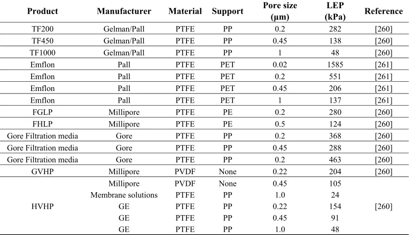
The most common materials used for MD membranes are poly(tetrafluoroethylene) (PTFE), poly(propylene) (PP) and poly(vinylidenefluoride) (PVDF) [53]. The porosity of the membranes used is in the range of 0.60 to 0.95, the pore size is in the range of 0.2 to 1.0 μm, and the thickness is in the range of 0.04 to 0.25 mm [6,52]. The surface energies and thermal conductivities of these materials are listed in Table 1.
Of these materials, PTFE has the highest hydrophobicity (largest contact angle with water), good chemical and thermal stability and oxidation resistance, but it has the highest conductivity which will cause greater heat transfer through PTFE membranes. PVDF has good hydrophobicity, thermal resistance and mechanical strength and can be easily prepared into membranes with versatile pore structures by different methods. PP also exhibits good thermal and chemical resistance [33]. Recently, new membrane materials, such as carbon nanotubes, fluorinated copolymer materials and surface modified PES [51,54–56], have been developed to make MD membranes with good mechanical strength and high hydrophobicity and porosity.
Sintering, stretching, and phase inversion are some of the methods to fabricate MD membranes from these materials [57–59].
Table 1. Reported surface energy and thermal conductivity of most popular materials used in MD [33,57–59].
Membrane Material Surface Energy (×10−3 N/m) Thermal Conductivity (W m−1 K−1)
PTFE 9–20 0.25
PP 30.0 0.17
PVDF 30.3 0.19
1.3.2. Characteristics of MD Membrane
Entry Pressure (LEP) of the membrane. In MD, the hydrostatic pressure must be lower than LEP to avoid membrane wetting. This can be quantified by the Laplace (Cantor) Equation [6] as following Equation (1):
(1) where B is a geometric factor, γl is the surface tension of the solution, θ is the contact angle
between the solution and the membrane surface which depends on the hydrophobicity of the membrane, rmax is the largest pore size, Pprocess is the liquid pressure on either side of the
membrane, and Ppore is the air pressure in the membrane pore.
Low surface energy, equivalent to high hydrophobicity. Based on Equation (1), material with higher hydrophobicity can be made into membranes with larger pore sizes, or membranes made from more hydrophobic material will be applicable under higher pressures for a given pore size;
Low thermal conductivity. High thermal conductivities increases sensible heat transfer and reduce vapor flux due to reduced interface temperature difference; and
High porosity. High porosity increases both the thermal resistance and the permeability of MD membranes, so both the heat efficiency and flux are increased. However, high porosity membranes have low mechanical strength and tend to crack or compress under mild pressure, which results in the loss of membrane performance.
The sintering method can be used to prepare PTFE membranes. In the sintering process, polymeric powder is pressed into a film or plate and sintered just below the melting point. The porosity of the membranes made in this manner is in the range of 10%–40% and typical pore sizes are in the range of 0.2 to 20 µm.
Stretching technology can be used to make PP and PTFE membranes. In this process, films are formed by extrusion from a polymeric powder at temperatures close to the melting point coupled with a rapid draw-down. The membranes made have pore sizes in the range of 0.2–20 µm and porosity of about 90% [33,53,65].
Phase inversion can be used to produce PVDF membranes. In this process, the polymer is dissolved in an appropriate solvent [66,67] and spread as a 20–200 µm thick film on supports, such as nonwoven polyester, PP backing material or PP scrim backing [53,67], and an appropriate precipitant (typically water) is added to split the homogeneous solution film into two phases (a solid polymer rich phase and a liquid rich phase). The prepared membrane has a pore size in the range of 0.2 to 20 µm, and porosity of approximately 80% [45].
Most of the polymeric materials for membrane fabrication are flexible and deformable under force, and the porosity of the MD membranes is generally greater than 80%. Therefore, it can be speculated that the membrane will be compressed under the hydrodynamic pressure incurred from the flowing feed and/or permeate flowing. As a result, the properties of the membrane, such as pore size, porosity, membrane thickness and thermal conductivity will be altered. These phenomena will become significant when the process is scaled up and longer membranes are employed. A flux reduction of 15%–39% was observed when the pressure in DCMD was increased from 1 kPa to 45 kPa by Zhang et al. [68,69]. DCMD Modelling identified that while compression increased the membrane permeability, it also led to increased thermal conductivity of the membranes, and overall membrane distillation performance decreased [69].
1.3.3. Membrane Fouling and Wetting
Membrane fouling is a major obstacle in the application of membrane technologies [70,71], as it causes flux to decline. The foulant, e.g., bio-film, precipitations of organic and inorganic matter, can reduce the permeability of a membrane by clogging the membrane surface and/or pores. Although membrane distillation is more resistant to fouling than conventional thermal processes, dosing of anti-scalants can be used to control scaling [72–74]. Dow et al. [75] also showed that lower feed temperatures can substantially reduce the influence of fouling in DCMD.
Since the hydrophobic MD membrane is the barrier between the feed and permeate, membrane wetting will reduce the rejection of the non-volatiles. Membrane wetting can occur under the following conditions:
The hydraulic pressure applied on the surface of the membrane is greater than the LEP; The foulant depositing on the membrane surface can effectively reduce the hydrophobicity of
the membrane [36,76], which was generally found in a long-term operation or in treating high-concentration feeds such as for brine crystallisation; and
In the presence of high organic content or surfactant in the feed, which can lower the surface tension of feed solution and/or reduce the hydrophobicity of the membrane via adsorption and lead to membrane wetting [77].
1.4. Heat Transfer and Mass Transfer Phenomena in MD
In MD processes, heat and mass transfers are coupled together in the same direction from the hot side to the cold side [78]. Figure 4 illustrates these processes in DCMD, which is typical for MD configurations. The feed temperature, Tf, drops across the feed side boundary layer to T1 at the
membrane surface. Some water evaporates and is transported through the membrane. Simultaneously, heat is conducted through the membrane to the cold (permeate) side. The cold flow temperature Tp
increases across the permeate boundary layer to T2 at the membrane surface on the cold side as water
vapor condenses into the fresh water stream and gains heat from the feed side. The driving force is, therefore, the vapor pressure difference between T1 and T2, which is less than the vapor pressure
difference between Tf and Tp. This phenomenon is called temperature polarization. The temperature
Figure 4. DCMD heat transfer and mass transfer through membrane.
1.4.1. Heat Transfer
Heat transfer from the feed side to the permeate side involves two steps [2]: First, the heat transfers from the hot side to the cold side across the membrane as sensible heat and latent heat, so as to form the temperature difference between boundary layer and bulk flow; second, the heat transfers from the bulk flow of the feed to the boundary layer via heat convection, due to the temperature difference arising from the first step. In the first step, as shown in Figure 4, the sensible heat is conducted through the membrane to the cold side, and the latent heat is carried by the water vapor, which is evaporated at the interface between the hot stream and membrane pores and is condensed at the interface between the pores and cold stream for DCMD [16].
According to the two heat transfer processes, the heat balance of the feed stream can be described by [78–80] with the following Equations (3–5):
(3) (4) (5) because , then
(6) where Q1 or Q2 are the total heat flux from the hot side to the cold side, λ is the thermal conductivity of
the membrane, b is the membrane thickness, ε is the membrane porosity, α is the convective heat transfer coefficient on the hot side, J is the permeate flux, and Hg is the enthalpy of the vapor.
As Equation (4) calculates the thermal conductivity assuming parallel heat flow through air and membrane material, it is appropriate for estimating the thermal conductivity as the tortuosity
striping gas is used in SGMD, which boosts the mass transfer and provides good resistance to sensible heat transfer, but there is more energy consumption from the blower and/or condenser if the permeate is the product [23,26,27]. In VMD, the sensible heat loss can even be neglected, if a very low vacuum is employed in the permeate chamber, but it would not be as competitive as DCMD and AGMD if the thermal energy cannot be recovered from the external condenser.
1.4.2. Mass Transfer
Mass transfer in the DCMD process includes three steps: firstly the hot feed vaporizes from the liquid/gas interface, secondly the vapor is driven by the vapor pressure difference and crosses from the hot interface to the cold interface through the pores, and thirdly the vapor condenses into the cold side stream [52]. Therefore, there are two major factors controlling the mass transfer: one is the vapor pressure difference, and the other is the permeability of the membrane.
If the fluid dynamics conditions on both sides of the membrane could be considered good, mass transfer through the membrane may be the limiting step for mass transfer in MD [83]. The influence of the physical properties on membrane permeability includes:
(1) The effective area for mass transfer is less than the total membrane area because the membrane is not 100% porous;
(2) For most practical membranes, the membrane pores do not go straight through the membrane and the path for vapor transport is greater than the thickness of the membrane; and
(3) The inside walls of the pores increase the resistance to diffusion by decreasing the momentum of the vapor molecules.
The mass transport mechanism in the membrane pores is governed by three basic mechanisms known as Knudsen-diffusion (K), Poiseuille-flow (P) and Molecular-diffusion (M) or a combination between these known as the transition mechanism [2,84]. The Knudsen number (Kn) is used to indicate the dominant mass transfer mechanism in the pores:
Kn = l/d (7)
where d is the mean pore size of the membrane; and l is the mean free path of the molecules defined by Kuhn and Forstering [85] and Albert and Silbey [86] as:
(8)
where kB is the Boltzman constant (1.381 × 10⁻²³ J/K), σw and σa the collision diameters for water
vapor (2.641 × 10⁻¹⁰ m) and air (3.711 × 10⁻¹⁰ m) [87,88], T is the mean temperature in the pores, and
the mean free path of the water vapor in the membrane pores is 0.11 µm. The pore sizes of the membranes used for membrane distillation are in the range of 0.2 to 1.0 μm, so Kn will be in the range of 0.5 to 0.1. Table 2 shows the dominating mass transfer mechanism based on the Kn [83] for different configurations.
Table 2. Dominating mass transfer mechanism in different MD configurations.
Configurations Component in
pores
Vapor Pressure
difference across pores Driving force
Mass transfer mechanism
(0.01 < Kn< 1)
DCMD Vapor-air mixture ∆P = 0 pressure differencePartial vapor M–K transition
AGMD Vapor-air mixture ∆P = 0 pressure difference Partial vapor M–K transition
SGMD Vapor-air mixture ∆P = 0 pressure difference Partial vapor M–K transition
VMD Vapor ∆P ≠ 0 pressure differencePartial vapor P–K transition
There are also two other popular mass transfer models for membrane distillation, which are Schofield’s model [79,88] and the dusty-gas model for DCMD [89,90]. In the “Dusty-Gas” model [89,91], the porous membrane is assumed to be an array of dust particles held stationary in space, and the dust particles in terms of the classical kinetic theory of gases are supposed to be giant molecules in the interactions between gas and surface. Based on this model, a general flux equation for a gas that permeates through a porous media in the Knudsen-viscous transition region can be described as:
(9a) in which
and (9b)
These equations of different mass transfer models can all be simplified to [52]: (10a) in which
(10 b) where a is an exponent coefficient in the range of 1–2.
From Equation (10b), it can be concluded that the flux for MD can be increased by increasing pore sizes and porosity and by reducing the tortuosity and thickness of the membrane. However, according to Equation (6), reducing the thickness of the membrane also increases the sensible heat loss from the hot side to the cold side, which leads to a reduction of water flux due to decreased interfacial temperature differences (vapor pressure difference). Therefore, there is an optimum membrane thickness for membrane distillation efficiency.
To minimize the sensible heat loss, the heat transfer coefficient (λ/b) of the membrane can be reduced by increasing the membrane porosity. This will also reduce the sensible heat transfer as
Comment [m8]: No Euqation number? If possible, please add a number. We can use 9.1, 9.2, or 9(a), 9(b), etc.
Change to 9a and 9b
Comment [VU9]: Added equation number and made as 10a and 10b
To maximise flux, it is necessary to increase the vapor pressure difference across the membrane or to reduce temperature polarization [92,93]. Therefore, it is necessary to improve the convective heat transfer coefficient for the purpose of producing more flux according to Equations (3), (5) and (6). The convective heat transfer coefficient can be expressed as Equation (11) according [94]:
(11) where λf is thermal conductivity of the feed, and is the temperature gradient in the
thermal boundary layer of the feed. From Equation (10b), it can be seen that the convective heat transfer coefficient can be improved effectively by reducing the thickness of the thermal boundary layer. As the thickness of the thermal boundary layer can be reduced by enhancing the stream turbulence, increasing flow rate can effectively improve the flux. However, the hydrodynamic pressure has a square relationship to the flow rate [95], and the increased pressure will diminish the effect of increasing turbulence if the membrane is compressible [68,69].
The presence of turbulence promoters, e.g., net-like spacers or zigzag spacers shown schematically in Figure 5 [96,97] can effectively reduce the thickness of the thermal boundary layer and improve
αf [98]. It is also important that high heat transfer rates are achieved with a low pressure drop in the
channels where the feed solution and cooling liquid are flowing [28,92,93,96,99]. From reported data [92], it is found that the temperature polarization coefficient of spacer-filled channels falls in the range of 0.9–0.97, in comparison with a temperature polarization coefficient 0.57–0.76 for flowing channels without spacers. The effect of Reynolds number on heat transfer for the spacer-filled flat channels is presented and discussed in [92,96,100].
(f is the angle between spacer fibres in the flow direction, lm is the distance between parallel spacer
fibres, is the hsp is the height of the spacer and df is the diameter of a single spacer fibre).
It is also noticed that the influence of turbulence on flux becomes less at higher turbulence levels. Therefore, it is necessary to control turbulence within an adequate range to reduce the energy cost associated with pumping.
1.5.2. Feed Temperature
As MD is driven by vapor pressures which vary exponentially with the stream temperature [52], the flux is affected greatly by the feed temperature. Furthermore, since the heat loss through themal conduction is linear to the temperature difference across the membrane as according to Equation (3), the proportion of energy used for evaporation will increase as the feed temperature increases [52]. However, an increase of temperature polarization due to the high flux and greater heat and mass transfer was also observed with rising temperature [52,53,69], but this can be reduced by using turbulence promotors such as spacers.
1.6. Modelling Aspects of Membrane Distillation
Mass transfer in MD is acompanioned by heat transfer, so MD Modelling is more complex than that for heat exchangers. The parameters or data that should be considered during Modelling include [2]:
Membrane characteristics, such as membrane thickness, pore size, tortuosity and porosity, which can be aquired by gas permeation experiment, scanning electron microscopy and image analysis [68,101];
Thermal conductivity of the membrane is measurable in some cases [102] or can be calculated with Equation (4) [14,51,68];
Convective heat transfer coefficient of the feed and/or permeate streams, which can be calculated by semi-emperical equations based on Nusselt numbers and by including factors such as the structure of the spacer or module, flow velocities, properties of feed and permeate, the operation temperature, etc. and
An important assumption adopted in Modelling MD is that the kinetic effects at the vapor-liquid interface are negligible. According to this assumption, vapor-liquid equilibrium equations can be applied to determine the partial vapor pressures of each component at each side of the membrane.
1.7. Applications of Membrane Distillation
Although MD is currently studied mostly at the laboratory scale, membrane distillation has potentially distinctive advantages in some particular areas [6,33]. There are several pilot plants currently undergoing field trials: for treating wastewater from a power plant (in Singapore) [35], wastewater in a chemical plant (The Netherlands) by Memstill®, and other wastewaters are currently
Membrane distillation may also be integrated with reverse osmosis processes to increase the water recovery in the desalination plants [109,112] by treating the brine. Lawson and Llyod [81] stated that membrane distillation can be a viable process for desalination, while Schneider et al. [82] have argued that small, portable desalination units utilising waste heat are more feasible for application of MD.
Membrane distillation also can be used for water treatment, such as removing heavy metals from wastewater [113], recovering HCl from cleaning solution in electroplating [114], concentrating sulphuric acid to recover lanthanide compounds in apatite phosphogypsum extraction process [115], eliminating radioisotopes, reducing the waste volume from nuclear industry [116] and removing volatile organic components from dilute aqueous solutions [21,22,117,118].
Due to the low feed temperature, MD can also be used for concentrating solutions in the food industry. It has been widely tested for the concentration of many juices including orange juice [18], apple juice [119] and sugarcane juice [120].
MD was also employed for selective extraction of volatile solutes and solvents for applications in the health and fermentation industries. Blood and plasma were treated by MD in order to promote a solute-free extraction of water from biomedical solutions without loss in quality [121,122]. Membrane distillation has also been suggested as an innovative tool to ameliorate treatment of uraemia by allowing purification of the blood ultrafiltrate and the re-injection of the purified water to the patients [123]. MD was also combined with a bioreactor to promote the reaction rate of ethanol fermentation by selectively removing ethanol [124].
Further discussion of applications is contained in Section 3. 2. Advances on MD Processes and Modules for Water Purification
Even though membrane distillation was patented in the 1960s [125], is has not been commercialised because of the success of competing technologies. However in just the last few years, MD has emerged with numerous commercially oriented devices and novel process integrations. This section focuses on the current process arrangements and commercially available MD systems.
2.1. MD Stand-Alone Systems
A module to house a membrane and perform MD is not complicated but requires more complexity in its connections as compared to pressurised membrane systems (micro, ultra and nanofiltration as well as reverse osmosis). As shown in Figure 6, we see the simplest form of DCMD configuration which will desalinate a saline water feed to a very high quality permeate.
However, the simplest form suffers drawbacks which must be overcome to make MD practically useful. The three key drawbacks under standard process configuration are:
Water recovery limit: The flux of the membrane draws a significant amount of energy purely through the evaporation of the feed, which is deposited into the permeate. The limiting amount of water permeated as a fraction of water fed, F, (i.e., single pass recovery) is presented according to [126] as Equation (12):
1
∆ vap (12)
Where TF and TE are the feed and exit temperatures, respectively (K or °C), CP is the specific
heat of water (4.18 kJ/kg/K), t is the proportion of conductive heat (balance due to evaporative heat) loss through the membrane, and ΔHvap is the latent heat of vaporisation (kJ/kg). For
example, if the feed water is supplied at 80 °C, no more than 7.7 wt % of this desalinated water will evaporate to the permeate (i.e., F) by the time this temperature is reduced to 20 °C (assuming t = 0.3). This is typically managed by reheating the cool brine reject and sending it back to the feed. In DCMD, this recirculation is likewise done on the permeate side. Both pumps will now be larger, by at least an order of magnitude, in order to achieve useful recoveries exceeding 50%.
Electrical energy constraints: The thermodynamics of the simple MD setup in turn constrains the electrical consumption. Each pump in Figure 6 will consume electrical energy per unit water permeated, Eelec,std (kWh/m3), according to:
elec,std
1
3600 (13)
where PF is the MD module feed pressure (kPa), and η is pump efficiency. If we assume
PF = 20 kPa, and pump efficiency of 0.6, each pump consumes 0.12 kWh/m3 of electricity.
Both pumps consume 0.23 kWh/m3. Clearly achieving low pressure drops along the module will have an impact on the electrical energy requirement of MD systems. This minimum is related to the point above, where F equates to around 7.7 wt %; and
Thermal energy constraints: Water evaporation energy per unit mass, ∆Hvap, is 2260 kJ/kg, or
628 kWh/m3. This energy is in the form of thermal energy, which is the standard thermal
energy required to operate the MD system in Figure 6. This value equates to a performance ratio (PR), or gain output ratio (GOR) of 1, being the mass ratio of water produced to the amount of steam energy (i.e., latent heat) fed to the process.
Comment [VU10]: Changed symbol for single pass recovery from f to F
2.2. State of the Art MD Research and Systems
The principal research activities on MD can be divided broadly into two categories: fouling/performance testing, and energy efficient process design. With fouling/performance design, fundamental understandings of the diffusion mechanisms coupled with heat and mass transfer has unlocked the critical science needed to select optimal operating conditions, membrane materials and module designs that ultimately give better flux performance for the same operational conditions [52,53,127]. Fouling of membranes has explored scaling issues for the classic applications in brine concentration [72,128], and the more novel application in dairy processing [129]. While this research progresses to uncover further fundamental improvements, the focus here is on the novel process configurations that address the performance limitations defined in Section 2.1. The most notable organisations specialising in MD modules or high efficiency systems are:
Fraunhofer ISE (AGMD); Memstill and Aquastill (AGMD); Scarab (AGMD);
Memsys (vacuum enhanced multi effect AGMD). 2.2.1. Fraunhofer ISE
One of the earlier MD modules to appear was an AGMD module from Fraunhofer Institute for Solar Energy System (ISE), Germany. The innovative aspect of their design was a spiral wound AGMD system as shown in Figure 7. AGMD has the advantage in that the module itself features internal heat recycling to minimise the loss of latent heat, thus greatly reducing the thermal energy requirement. They propose to have achieved thermal energy consumptions of 140 to 200 kWh/m3 in their 2003 device [130], or greater than 4 fold improvement in the latent heat required to evaporate the same amount of water (GOR up to 4.5).
Figure 7. (a) Section of Fraunhofer ISE’s spiral wound AGMD module: (1) condenser inlet; (2) condenser outlet; (3) evaporator inlet; (4) evaporator outlet; (5) distillate outlet; (6) condenser channel; (7) evaporator channel; (8) condenser foil; (9) distillate channel and (10) hydrophobic membrane; (b) Picture of the modules [42].
(a) (b)
Comment [m12]: Please confirm that you have obtained the permission. Then we may add a sentence like: Reprinted with permission from [42]. Copyright 2011 Elsevier.
Scientific Research) and emerged around 2006. Memstill was also based on the energy efficient AGMD concept (see Figure 8) and is probably one of the longest running projects trialling MD [34]. Memstill was developed by a consortium consisting of TNO and Keppel Seghers Belgium N.V. A costing based on Memstill’s system revealed that desalination by MD can reduce desalinated water costs to within the range of $0.26 to $0.50 per m3 water treated depending on the cost of the thermal
energy
provided [29]. The principle reason for this observed saving was cheaper plant materials to build their module in comparison to RO (RO uses high pressure vessels), and ability to utilise low cost heat sources (i.e., waste heat) as the principle energy source. Memstill pilots have been operating since 2006 fed with raw seawater, with the first in Singapore, two in the Netherlands at the E.ON Benelux Power Plant, then a more recent trial at BASF, Port of Antwerp running until March 2011. A less successful trial (third Memstill trial) was conducted on brackish water from the harbour of Rotterdam, failing due to lack of monitoring and incorrect pre-treatment [131]. Trialling has featured modules containing up to 300 m2 of membrane area. Current plans are to operate at 100 m3/day scale on a
petroleum refinery in Singapore located on Jurong Island [132]. The thermal energy required, claimed by Memstill in its years of trials, is as low as 56 to 100 kWh/m3 water produced (GOR up to 11.2).
This is the lowest value reported from real testing (or highest GOR), but to achieve this, the water must be heated to 80–90 °C. The electrical energy required was assumed to be 0.75 kWh/m3 [133].
Figure 8. Concept of the Memstill process based around AGMD [133].
Comment [m13]: Permission?
The Memstill technology has been licenced to Aquastill and Keppel Seghers for industrial module production. In 2008 and 2009, there was a large investment to reduce the cost of the MD modules [131]. In June 2012, Aquastill’s website indicates the availability of both air gap and direct contact MD modules as shown in Figure 9. These are in spiral wound configuration.
Figure 9. Aquastill process configurations as found on the Aquastill’s website. Left configuration based on AGMD and right configuration based on DCMD with heat recovery.
2.2.3. Scarab AB
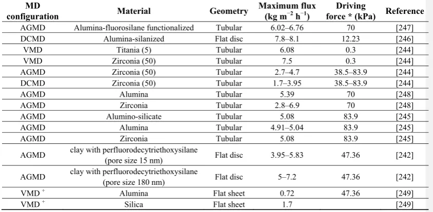
The Scarab AB system features an AGMD module, and has been trialled on numerous projects worldwide. The Scarab AB system has been trialled on solar ponds in 2004 by University of Texas at El Paso sponsored by the US Bureau of Reclamation [134,135], and using solar thermal collectors in Spain and Mexico by the MEDESOL project starting in 2008 [136]. In 2011, a trial under the MEDESOL project lasting 4 months was reported, finding issues related to membrane wetting over the longer term, fluxes of up to 6.5 kg m−2 h−1, and thermal consumption of 810 kWh/m3 [137] (GOR of 0.78). In the same year, results were reported utilising five Scarab AB modules producing 1–2 m3/day,
trialled on a co-generation facility in Sweden (collecting the exhausted heat from power generation to send to district heating) [138]. The interesting feature of this work was the long term treatment of municipal water and flue gas condensate. The modules used in this trial, shown in Figure 10, involves a plate and frame design with each featuring a 1 mm air gap, 2.3 m2 membrane area, nine feed and nine
2.2.4. Memsys
The Memsys system is a relatively new MD technology that features a novel internal heat recycling concept that allows for reduced thermal consumption. The heat recycling shown in Figure 11, known as Vacuum-Multi-Effect-Membrane-Distillation (V-MEMD) utilises a multistage setup integrated into a compact plate and frame module. In doing this, Memsys has been regarded as state of the art in the MD technology field, as it has achieved a unique compromise in thermal energy consumption, membrane flux and module compactness. In its current state of development, since module production started in 2010, technical articles with trial results are currently unavailable. Pilot plants have been installed around the world, including in Singapore, Australia and India [140–142]. Memsys promises thermal energy requirements of 175–350 kWh/m3 (GOR up to 3.6) and electrical energy requirement
of 0.75–1.75 kWh/m3. Memsys requires feed temperatures from 60 to 100 °C and cooling <40 °C.
Figure 11. The new high thermal efficiency Vacuum-Multi-Effect-Membrane-Distillation
(V-MEMD) process from Memsys [140]. Comment [m15]: Permission?
Separate document
Comment [m16]: Higher resolution if possible
Memsys modules are 330 mm × 700 mm × 480 mm in dimension, with 3.5 m2 of both MD and
condensation membranes. The MD membrane is made from PTFE and the condensation membrane is made from metal coated PP. Fluxes of Memsys systems have been demonstrated in the range of 6.8 to 9.5 kg m−2 h−1. Current module capacity is specified at 50 m3/day [140].
2.3. Hybrid MD Systems
MD is a separation process that offers several unique features that conveniently allow it to be integrated within other membrane operations. Most commonly, MD is integrated into RO, nano-filtration (NF), and the more developmental forward osmosis (FO).
2.3.1. MD Integration with RO or NF
One of the most logical technology partners for MD is RO or NF. There are two ways in which they can be integrated. The first is by using the RO brine as feed to the MD, or the NF or RO permeate as feed to the MD. These are represented in the flow diagrams presented in Figure 12.
Figure 12. Simplified flow diagrams of hybrid RO/NF-MD systems. MD connected to RO concentrate (a) and to RO/NF permeate (b). Here NF is nano-filtration, FO is forward osmosis, RO is reverse osmosis.
(a) (b) Using RO brine as a feed to MD (Figure 12a) has a great potential for MD utilization. This directly
addresses the upper concentration limit of RO at around 70,000 mg/L, as MD is far less influenced by salt concentration. Typically, the need for an RO-MD process to increase water recovery is for inland applications where disposal of the brine is an issue. Testing of MD on RO groundwater concentrates revealed that the concept is indeed viable, but suffers from practical issues such as scaling on MD membranes [143]. A similar result was found for an RO-MD trial on a solar powered direct contact MD system in rural Victoria, Australia [104]. Membrane scaling led to flux declines, but flux was easily restored using an acid clean. Scaling was found to be effectively managed by cleaning or the addition of anti-scalant. For the RO-MD process, the individual RO recovery was 89%, and MD recovery was 80%, giving a total water recover of 98% for the combined system [143].
simple filter at the module entrance. 2.3.2. MD Integration with FO
Forward osmosis (FO) is an emerging low pressure water treatment process that relies on the natural osmotic force to transfer water through a semi-permeable membrane from one solution to another. These solutions have differing dissolved solid contents, which means that while the water has been taken from a non-potable saline solution (e.g., seawater), it must be removed from the second solution (draw solution) to become useable pure water. MD has been proposed for this second removal step in novel space or protein concentration applications [145–147], schematically represented in Figure 13. Although little explored, FO could recover water from a brine with scaling salts such as groundwater or seawater into a pure NaCl draw solution. The draw solution is then reconcentrated by MD, and fresh water is recovered.
Figure 13. Simplified flow diagram of FO-MD process for water desalination.
2.4. MD Crystallization
MD fluxes can remain relatively high at salt concentrations much higher than for RO [148]. MD, therefore, has a logical use in zero (or near zero) liquid discharge applications; however, precipitating salts must be managed to enable the high recoveries. MD crystallization has been proposed to remove the scaling/precipitating salts to maximise MD concentration factors [149–151]. The concept of an MD crystallization experiment is shown in Figure 14. MD crystallizers have been explored for model NaCl and Na2SO4 solutions, increasing salinity above saturation [149,151] and for sea water
have also been explored in other industries, for example in drug development [153]. The merger of MD with crystallisation, therefore, is an emerging area for MD and can expand to various industries.
Figure 14. Experimental setup of the MD crystallization used by Tun et al. [149].
2.5. Recent MD Processes and Modifications
2.5.1. Keppel Seghers
A new module based around AGMD has been produced by the Singaporean enterprise Keppel Seghers. Two prototype units, “Module A” and a multistage “Module B” have been produced as shown in Figure 15, featuring 9 m2 of flat sheet membrane in each module [154].
Figure 15. Keppel Seghers MD modules based around AGMD: a) module A and b) multistage module B [154].
Comment [m17]: This figure was cut more of the top margin. Please provide a new version.
Downloaded a new version but very similar to the previous figure.
Permission sent in separate documentation
Comment [m18]: Permission?
Utilising the same solar field in Spain for the MEDESOL project [137], a 7 month trial was run in 2009 using the Keppel Seghers MD modules. Fluxes of up to 3.5 kg m−2 h−1were achieved using “Module A” and up to 5.5 Lm2/h using “Module B”. To achieve these fluxes, temperatures around
80 °C were fed to the modules. Best thermal consumption of 294 kWh/m3 (GOR of 2.1) was reported using multistage “Module B”.
2.5.2. Compact AGMD Modules
A compact, small-scale and flexible AGMD unit was presented in 2012 by Cipollina et al. [142]. The unit has planar plate and frame geometry for easy assembly and disassembling, counter-current flows with internal heat recovery for thermal efficiency enhancement and cheap polymeric material (Figure 16). The system could be easily extended from single-stage to multi-stage units, and coupled with a polymeric heat exchanger for feed brine heating by means of solar energy or waste heat. The system can produce fresh water for small communities located in remote areas with potentially large availability of non-conventional energy sources.
Figure 16. MD configuration with planar geometry [142].
Comment [m19]: Permission?
2.5.3. Membrane Distillation Heat Exchanger (MDHX)
As shown in Figure 17, the MD heat exchanger (MDHX) proposes a MD concept where the heat is coupled directly into the MD module by directing separate process streams into the MD module to both supply and remove heat from the MD channels [155,156]. The benefits include conveniently merging MD and process heat exchange into a single unit, but also it allows for direct heat conduction where it is lost. This overcomes the limitation presented in Equation (13), yielding no theoretical limit on single pass recovery.
Overcoming the single pass recovery limit was first explored theoretically by considering a module that condenses vapor on a heat transfer plate running in parallel to the membrane to supply the latent heat to the MD channel (Figure 18). The latent was then removed on the cold side of the MD channels by another parallel plate that boiled a fluid [126]. Despite promising improved single pass recovery that reduces the electrical energy requirement proposed in Equation (13), condensing/boiling vapor within a module is practically difficult and no experimental validation was presented. Instead, the MDHX concept is more practical, and the concept was validated with experimental data [155,156].
Figure 17. Concept of MDHX system that couples heat directly to the MD process [156].
Figure 18. Concept of adding and removing heat directly from the MD module to overcome single pass recovery constraints [126].
Comment [m20]: Permission?
Yes – permission in separate documentation
Comment [m21]: Permission?
Early experimental work demonstrated that single pass recoveries can be increased from 2% to 14%, which leads to an electrical energy consumption <0.01 kWh/m3. Meanwhile, the thermal energy
requirement is high, at around 1200 kWh/m3, so the simple form of the MDHX module has better applications in abundant, low temperature (<40 °C) waste heat applications. Higher thermal efficiency configurations are possible, but unexplored at this time.
2.5.4. DCMD Module Improvements
In 2012, Yu et al. presented computational fluid dynamics results on the benefits of improving the flow conditions in DCMD modules [157]. They used DCMD hollow fiber modules with and without annular baffles attached to the shell wall to investigate the effect of the intrinsic mass-transfer coefficient of the membrane on the module performance. The baffled module provided a significant mass flux improvement compared to a non-baffled module at a higher temperature. They suggested that by adding the baffles the fluid dynamics of the systems may improve and reduce the degree of temperature polarization (TP), which is believed to be one of the main causes responsible for low water flux. However, the added turbulence has an electrical energy penalty following Equation (13), as the module backpressure would in turn increase. The improved flux would have to outweigh the increased pressure to ensure the electrical energy requirement is not substantially increased.
3. Advances on MD Applications for Water Purification
Membrane distillation has important advantages that enable coupling with waste heat or renewable energy-driven systems such as geothermal or solar energy. Some advantages include the ability to operate at lower temperatures (50 °C to 80 °C), at higher brine concentrations and at lower pressures than other thermal-driven or pressure driven systems. Other advantages are the ability of the system to operate intermittently without causing damage to the membrane module or to the membrane if it dries out, and minimal chemicals are required for pre-treatment of the feed water [136,158].
3.1. MD and Renewable Energies
3.1.1. MD-Solar Systems
MD with solar energy collectors is the ability for MD to tolerate fluctuating and intermittent operating conditions and to operate with low grade thermal energy [159]. The operating temperatures of MD are similar to the temperatures at which solar collectors exhibit highest efficiency [43]. The energy generated by the solar collectors and PV panels can provide the thermal energy supply for the low operating temperatures required by MD [160]. It was reported that even though the initial cost of a MD solar system is a limitation, once the system is installed and in operation, the operational and energy costs are minimal [159]. A recent study [161] showed that for the AGMD system, increasing the feed inlet temperature had a significant effect in lowering the cost while high feed flow rate resulted in increasing water production cost. In solar panel (SP)-MD systems, the MD configuration will impact the final cost of the water.
Bench- and pilot-scale studies have been undertaken on solar MD [43,130,137,159,161–166]; however, they are still few compared to studies with the more mature technology of solar PV-driven RO and solar distillation. A solar MD system was tested to recover water and reduce brine volumes from RO concentrates by Dow et al. [75]. The system consisted of evacuated solar tubes for collection of the required thermal input and a flat sheet MD module. The solar panels were capable of reaching 60 °C, with efficiency as high as 70%. The researchers found a reduction of the performance of the solar panel to nearly half of the design capacity due to solar energy variability caused by external factors such as cloudy and rainy weather. They also found reduction of the module performance due to gradual scale build up inside the module. The RO concentrate that fed the MD systems contained approximately 3300 mg/L TDS with 200 mg/L calcium, 100 mg/L magnesium, 200 mg/L sulfate, and 350 mg/L carbonate/bicarbonate. It also contained antiscalant which was added during the RO stage. The conductivity of permeate produced was <50 µS/cm at a flux of 3.6 kg m−2 h−1.
Deng [167] found a decrease in thermal efficiency with time when using a flat solar collector to heat the feed water entering to a hollow fiber MD module, and attributed it to sunshine, wind, and cloud coverage. The purpose of the solar collectors was to provide the heat needed by brackish feed water entering the MD system. The maximum efficiency of the standard and flat panels evaluated was 32.75% and 70%, respectively. The thermal efficiency of a homemade solar panel was also evaluated by the author, and found it to be only 5% due to lack of proper insulation of the cover glass to retain the heat adsorbed by the collector.
An air gap membrane distillation (AGMD) module with a surface area of 9 m2 was tested for seawater desalination using a solar multistage MD system with a potential capacity of 0.5 m3/d to
50 m3/d [136,160]. The heat source for the feed water used in the system was a compound parabolic solar concentrator. The system required a specific heat consumption of 1400 kWh/m3 with a total
maximum distillate production of 20 L/h per module and a maximum single pass recovery ratio of 2% per module. Another AGMD module with a total surface area of 2.8 m2 was coupled with a static solar
collector field (Compound Parabolic Collector type) and tested during solar hours (Figure 19) [137]. The system was integrated into a multistage layout to minimize energy consumption. A non-fouling coating for heat exchangers was used to avoid scaling. The MD system proved to be suitable for coupling with transient solar thermal energy but scale-up from laboratory scale affected specific distillate production and thermal consumption. A maximum specific distillate flux of 71 kg m−2 h−1
Table 3. Examples of reported solar-powered MD modules.
System Collector
area Capacity Flux
Water
application Reference
Solar pond + AGMD 2.94 m2 – 6 kg m−2 h−1 – [134]
Flat plate collector + hollow fiber MD 3 m2 50 L/day 17 L/m2 day – [168]
Flat plate and vacuum tube collector MD 12 m2 40 L/h – – [169]
Flat plate collector + spiral wound MD 10 m2 100 L/day – brackish [170]
Solar collector + hollow fiber VMD 8 m2 – 32.2 kg m−2 h−1 groundwater [171]
Parabolic solar concentrator – – 71 kg m−2 h−1 seawater [172]
parameters and selection of set point settings. Proportional–integral–derivative (PID) control systems have proven to be robust and are the most used by industry [173]. The authors suggest the use of an interior coil heat exchanger configuration for higher thermal energy absorption and longer operation time. Small and large scale stand-alone solar MD desalination systems have been developed to provide potable water in remote areas that lack both electricity and drinking water but have abundant solar irradiation [40]. A summary of commercial solar-powered MD systems is presented in Table 4. Fraunhofer ISE developed solar thermally driven compact desalination systems based on spiral wound MD for capacities between 100 and 500 L/day and larger systems of up to 10 m3/day. Eight pilot plants
were installed in five different countries, i.e., Grand Canaria, Egypt, Jordan, Germany, and Italy [130,162,165,174]. The compact system in Italy was powered by a hybrid system using solar energy and waste heat from diesel engines [142].
Table 4. Multistage pilot and commercial solar-powered membrane distillation system [40,130,137,142,165,174].
Properties Scarab Medesol Memstill Memsys Smades
Configuration AGMD AGMD AGMD VMD Spiral wound MD
Surface area 2.3 m2 2.8 m2 9 m2 – 72 m2
Membrane material PTFE PTFE – – PTFE
Capacity 1–2 m3/day 0.5–50 m3/day 80 m3/day
50 m3/day 1 m3/day 600–800 L/day Permeate flux 12–27 kg m−2 h−1 5–10 kg m−2 h−1 – – 2–11 L/m2 day Thermal energy
Consumption 5–12 kWh/m
3 810 kWh/m3 22–90 kWh/m3 175–350 kWh/m3 200–300 kWh/m3
Electricity
comsumption 0.6–1.5 kWh/m
3 – – 0.75–1.75 kWh/m3 –
Test sites Sweden Spain Singapore
Rotterdam Singapore Jordan
Stage Commercialised Pilot plant Pilot plant Commercialised Pilot plant
temperature. In his experimental work Bouguecha et al. [175] found that the MD recovery fraction is not very high by using only the sensible heat from a geothermal well. To increase the recovery ratio, the researcher proposed coupling solar collectors with the geothermal energy. Hardness and coupling of FBC to MD are some of the difficulties encountered when attempting to obtain waste heat from geothermal water [175]. In geothermal areas with hot spring temperatures ranging from 145 °C to 170 °C, brackish water is cooled to irrigate greenhouses and feed desalination plants. In the cooling process, a significant quantity of thermal energy is rejected to the atmosphere. Temperature requirements of traditional thermal desalination plants cannot be afforded by the supply of geothermal resources. Hot spring underground water contains minerals and dissolved organic material, including sodium, calcium, sulfate, and chloride. They can precipitate as the spring water discharges at the land surface [177]. Geothermal renewable energy can provide suitable and reliable heat supply for MD. However, the MD recovery fraction may not reach a high value using only the sensible heat from geothermal wells. Additional studies are required to explore the feasibility of coupling other energy systems with geothermal energy and MD with the purpose of increasing recovery ratio. Studies are also required to determine scaling and fouling caused by the hardness of the geothermal water. An economic analysis on geothermal MD was conducted by Bouguecha et al. [175] and is presented in Section 6.
3.1.3. Industrial Wastewaters
MD has been used to desalt hot brines and other aqueous solutions at feed temperatures below 100 °C. However, the potential to apply this technology to treat feed solutions above 100 °C was not explored until recently. This is an additional advantage for MD over other traditional membrane separation processes like RO, which cannot utilize the heat available in the feed solution and requires additional energy for cooling of the feed solution. Singh and Sirkar [178] used DCMD with PTFE membranes to treat produced water at 80–130 °C obtained from steam assisted gravity drainage (SAGD). The produced water had a TDS concentration of 10,000 mg/L. Even though the pressure of the solution went up to 2–3 atm, the membrane did not show leakage of salt under the experimental conditions tested. The water generated from this process may be used for steam generation in the SAGD process.
Global water scarcity and high oil prices have accelerated research to develop novel hybrid MD systems using renewable energy or waste energy. A freeze desalination and MD hybrid process was developed using waste cold energy released from re-gasification of liquefied natural gas (LNG) [179]. Researchers demonstrated that utilizing LNG cold energy greatly reduced the total energy consumption of the hybrid process with a total water recovery of 71.5%. It was reported that the water quality obtained met the standard for drinking water.
Another important source of waste heat is the nuclear industry which is dominated by nuclear power stations. When working with liquid radioactive waste, the chemical and radiochemical composition of the effluents and their activity and total salinity has to be taken into account. Radionuclides, which are present in liquid low-level radioactive waste in ionic form, have been separated using a spiral wound MD module with hydrophobic PTFE membrane [180]. Zakrzewaska et al. [180] reported that MD allows complete removal of radioactive species in one stage as compared to the multiple-stages process required with RO, and does not require additional processes to ensure sufficient purity of effluent discharged to the environment. The PTFE hydrophobic membranes used by Zakrzewska [180] showed good resistance to ionising radiation and strong chemical environments. The authors reported MD as a potential candidate for treating liquid low-level radioactive waste.
Zakrzewaska et al. [116] also proposed MD to concentrate the radioactive substances separated from the non-active portion into a small volume for subsequent conditioning and disposal. The author reported that one of the main advantages of MD over reverse osmosis, which has already been implemented by the nuclear industry, is that there is no adsorption of ions such as 50Co2+, 137Cs+, and 134Cs+ inside the membrane pores; and the generation of secondary waste is minimized.
Zakrzewaska et al. [181] also showed the existence of a diffusion isotope effect in membrane distillation that enhances the separation factors for H2O/HDO and 16H2O/18H2O enrichment.
Khayet et al. [182,183] conducted a comparative study of MD configurations for nuclear desalination. He proposed coupling DCMD with a nuclear reactor for water desalination and for low- and medium-level radioactive liquid waste concentration as an alternative integrated system for water and wastewater management in nuclear power plants.
and the difficulties with long term operation connected with the risk of membrane wettability. Spiral wound MD modules have a thermal energy consumption of about 600 kWh/m3 [180]. An alternative is
to use MD for small and medium capacity plants utilizing waste heat or other cheap energy sources. An advantage of implementing MD in the nuclear industry is that a lot of waste heat can be recovered in many points around nuclear cycles and reused for technological purposes [180]. Hybrid RO-MD systems may also be applicable in the nuclear industry to improve both the efficiency of the RO process and the decontamination factor. The decontamination factor is calculated as the ratio of activity concentration of feed to activity concentration of permeates [184]. RO systems supplemented with MD units can help recover large quantities of high enthalpy streams and waste heat [180].
An increasing industrial application for MD is the treatment of wastewater resulting from the textile industry, including the purification of dye solutions. Typical treatment technologies for treating dye solutions are coagulation/flocculation, adsorption and oxidation by ozone or chlorination [185]. Recent studies coupled traditional treatment methods with DCMD [186,187]. Banat et al. [188] studied the potential applicability of VMD to separate methylene blue dye from aqueous solutions. In a more recent study VMD with PP membrane was used to concentrate solutions containing different amounts and types of dyes [185] while recovering pure water. The authors observed a decay in the permeate flux for all dyes studied, which was attributed to membrane fouling. Membrane swelling was also observed.
Inorganic concentrates from RO and other desalination technologies can be potentially separated into high quality chemicals and reusable water using MD. Membrane distillation crystallization (MDC) has been proposed to recover concentrated solutions of magnesium sulfate from brines [189]. Water activities for concentrated solutions of varying ratios of sodium chloride and epsomite have been calculated using geochemical software. It has been established that the addition of a crystallizer stage after MD treatment reduces both the cost and environmental impacts due to brine disposal [189]. The performance of MD can, however, be influenced if the crystallization of salts takes place inside of the membrane module. Therefore, an evaluation of the kinetics of the crystallization process has to be understood. Kinetic studies on the crystallization of NaCl, Na2SO4, and CaCO3 have been conducted
by Curcio et al. [190], Drioli et al. [191]; and Gryta [192,193]. Drioli et al. [191] used MDC to generate supersaturation in the salt crystallization process and recover CaCO3, NaCl, and
MgSO4·7H2O from nanofiltration retentate. The influence of high concentrations of salts such as NaCl,
MgCl2, Na2CO3 and Na2SO4 on permeate flux as well as rejection factors in a solar power system

![Figure 8. Concept of the Memstill process based around AGMD [133].](https://thumb-us.123doks.com/thumbv2/123dok_us/7926807.1316148/22.595.158.333.512.716/figure-concept-memstill-process-based-agmd.webp)

![Figure 11. The new high thermal efficiency Vacuum-Multi-Effect-Membrane-Distillation (V-MEMD) process from Memsys [140]](https://thumb-us.123doks.com/thumbv2/123dok_us/7926807.1316148/24.595.99.566.57.765/figure-thermal-efficiency-vacuum-effect-membrane-distillation-process.webp)
![Figure 14. Experimental setup of the MD crystallization used by Tun et al. [149].](https://thumb-us.123doks.com/thumbv2/123dok_us/7926807.1316148/27.595.71.411.197.540/figure-experimental-setup-md-crystallization-used-tun-et.webp)
![Figure 16. MD configuration with planar geometry [142].](https://thumb-us.123doks.com/thumbv2/123dok_us/7926807.1316148/28.595.135.349.142.367/figure-md-configuration-planar-geometry.webp)
![Figure 19. Schematic diagram of solar MD experimental prototype at PSA, Spain [137].](https://thumb-us.123doks.com/thumbv2/123dok_us/7926807.1316148/32.595.30.563.104.540/figure-schematic-diagram-solar-experimental-prototype-psa-spain.webp)
![Figure 20. (a) Flow diagram for the NASA DOC wastewater treatment process, DO (DOC#1) and dual DO/OD (DOC#2); (b) Mass transport in the DO/OD membrane process in DOC#2; (c) Cross section of the DOC#2 plate-an-frame design [147]](https://thumb-us.123doks.com/thumbv2/123dok_us/7926807.1316148/38.595.85.574.331.688/figure-diagram-wastewater-treatment-process-transport-membrane-section.webp)