Electronic Thesis and Dissertation Repository
4-18-2012 12:00 AM
Design, Implementation and Evaluation of a Microgrid in Island
Design, Implementation and Evaluation of a Microgrid in Island
and Grid Connected Modes with a Fuel Cell Power Source
and Grid Connected Modes with a Fuel Cell Power Source
Andrew T. Moore
The University of Western Ontario Supervisor
Dr. Jin Jiang
The University of Western Ontario
Graduate Program in Electrical and Computer Engineering
A thesis submitted in partial fulfillment of the requirements for the degree in Master of Engineering Science
© Andrew T. Moore 2012
Follow this and additional works at: https://ir.lib.uwo.ca/etd Part of the Power and Energy Commons
Recommended Citation Recommended Citation
Moore, Andrew T., "Design, Implementation and Evaluation of a Microgrid in Island and Grid Connected Modes with a Fuel Cell Power Source" (2012). Electronic Thesis and Dissertation Repository. 493. https://ir.lib.uwo.ca/etd/493
This Dissertation/Thesis is brought to you for free and open access by Scholarship@Western. It has been accepted for inclusion in Electronic Thesis and Dissertation Repository by an authorized administrator of
MICROGRID IN ISLAND AND GRID CONNECTED MODES
WITH A FUEL CELL POWER SOURCE
(Spine title: DESIGN & EVALUATION OF A GRID CONNECTED &
ISLAND MICROGRID)
(Thesis format: Monograph)
Volume 1 of 2
by
Andrew T. Moore
Graduate Program in Electrical
and Computer Engineering
A thesis submitted in partial fulfilment
of the requirements for the degree of
Master of Engineering Science
School of Graduate and Postdoctoral Studies
The
University
of
Western Ontario
London, Ontario, Canada
School of Graduate and Postdoctoral Studies
CERTIFICATE OF EXAMINATION
Supervisor
______________________________ Dr. Jin Jiang
Supervisory Committee Dr. Rajiv Varma Dr. Amirnaser Yazdani
Design, Implementation and
Connected Modes with a Fuel Cell Power Source
is accepted in partial fulfillment of the
18-April-2012 __________________ Date
ii
School of Graduate and Postdoctoral Studies
CERTIFICATE OF EXAMINATION
Supervisor
______________________________ Dr. Jin Jiang
Supervisory Committee Varma
Yazdani
Examiners
______________________________ Dr. Rajiv Varma
______________________________ Dr. Gerry Moschopoulos
______________________________ Dr. M. Hesham El Naggar
The thesis by Andrew T. Moore
entitled:
Design, Implementation and Evaluation of a Microgrid in Island and Grid Connected Modes with a Fuel Cell Power Source
is accepted in partial fulfillment of the requirements for the degree of
Master of Engineering Science
_____________________________________________ Dr. Quazi Mehbubar Rahman Chair of the Thesis Examination Board
______________________________ Rajiv Varma
______________________________ Gerry Moschopoulos
______________________________ M. Hesham El Naggar
a Microgrid in Island and Grid
iii
ABSTRACT
The ability to connect a microgrid to the grid is an important step in the development and evolution of the modern power system. The principle objectives of this research are (1) to simulate a simple microgrid consisting of a PEM hydrogen fuel cell, load and connection to the grid and (2) to evaluate the resulting microgrid control system on a corresponding experimental microgrid.
The microgrid simulation demonstrated that the control algorithms can operate the microgrid in both islanded (VSC with voltage and frequency regulation) and grid connected (VSC with current control for power transfer).
The experimental laboratory microgrid was constructed and operated in real-time performing its black start and managed transitions between island and grid connected modes of operation. The synchronization method adjusted the island microgrid to become in phase with the grid and tracked well under steady state and load changing conditions. The synchronization process brought the island in phase with the grid within 400 ms. Passive island detection was demonstrated with the restoration to grid operation. The grid connected voltage and current THD were under 1%.
Keywords: Microgrid, Interconnection, Synchronization, Voltage Source Converter,
iv
ACKNOWLEDGMENTS
I wish to express my sincere thanks to my supervisor Dr. Jin Jiang for his guidance, support and patience. This research would not be possible without financial support from the University of Western Ontario, the Natural Sciences and Engineering Research Council (NSERC), the Ontario Research Fund (ORF) and the Ontario Fuel Cell Research and Innovation Network (OFCRIN). I would also like to acknowledge the valuable feedback and advice provided by my research advisory committee members: Dr. Rajiv Varma and Dr. Amirnaser Yazdani as well as the assistance of Dr. Xinhong Huang who is the research engineer with the Distributed Generation Laboratory at UWO. My thanks also go out to the other members of the DG Lab at UWO for their assistance and support.
v
DEDICATION
vi
TABLE OF CONTENTS
Volume I
CERTIFICATE OF EXAMINATION ... ii
ABSTRACT ... iii
ACKNOWLEDGMENTS ... iv
DEDICATION ... v
TABLE OF CONTENTS ... vi
LIST OF TABLES ... xix
LIST OF FIGURES ... xxi
LIST OF APPENDICES ... xviii
DEFINITIONS AND NOMENCLATURE ... xxix
1 INTRODUCTION ... 1
1.1 Motivations ... 1
1.1.1 Evolving Power System ... 1
1.1.2 Microgrids ... 1
1.1.3 Smart Grid ... 2
1.1.4 Applications Utilizing Microgrids ... 3
1.2 Problem Statements ... 3
vii
1.2.2 Islanding Detection ... 4
1.2.3 Ride-Through Capability ... 4
1.2.4 Control Algorithm ... 4
1.2.5 Interconnection ... 5
1.2.6 Unregulated Fuel Cell ... 5
1.3 Objectives ... 5
1.4 Scope of Research ... 6
1.5 Contributions ... 7
1.6 Challenges ... 7
1.6.1 Standards ... 7
1.6.2 Laboratory Microgrid ... 8
1.6.3 Power Quality ... 8
1.7 Organization ... 8
1.8 References ... 12
2 MICROGRID BACKGROUND ... 14
2.1 Microgrids ... 14
2.1.1 Microgrid and Distributed Generation ... 15
2.1.2 Classifications of LV Microgrid Applications ... 16
2.1.3 Benefits of Microgrids ... 17
2.2 Microgrid Operation ... 20
2.2.1 Essential Components ... 20
2.2.2 Microgrid Control ... 21
2.2.3 Standards and Guidelines ... 21
2.2.4 Interconnection Protection ... 22
2.2.5 Safety ... 22
2.3 Laboratory Microgrid ... 23
viii
2.3.2 Fuel Cell ... 24
2.3.3 Inverter ... 24
2.3.4 PCC (Point of Common Coupling) ... 24
2.3.5 Load ... 24
2.4 Microgrid Components ... 25
2.4.1 Power Electronic Interface ... 25
2.4.2 Interconnection Rack ... 26
2.4.3 dSPACE Real-Time Controller ... 27
2.5 References ... 28
3 MICROGRID OPERATION ... 30
3.1 Power Flow ... 30
3.1.1 General Principles ... 30
3.1.2 Power Flow in a Microgrid ... 33
3.1.3 Grid Connected Power Delivery ... 36
3.1.4 Island Operation Power Delivery ... 36
3.2 Connection State ... 38
3.2.1 Grid-To-Island Transition ... 39
3.2.2 Island-To-Grid Transition ... 39
3.3 Power Quality ... 39
3.3.1 Harmonic Distortion ... 40
3.3.2 Voltage Dip ... 42
3.3.3 Microgrid Impact on Power Quality ... 42
3.4 Islanding ... 44
3.4.1 Islanding Policies ... 44
3.4.2 Islanding Standards ... 45
3.4.3 Island Indicators ... 46
3.4.4 Passive Island Detection ... 46
ix
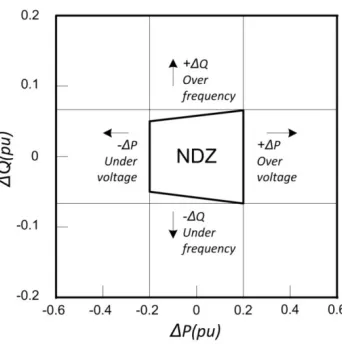
3.4.6 Non Detection Zone ... 47
3.5 Interconnection ... 48
3.5.1 Grid Connection Implementation ... 49
3.5.2 Connection Requirements ... 49
3.5.3 Protection Design ... 50
3.5.4 Single Line Protection Overview ... 51
3.5.5 Protection Enhancements ... 52
3.6 Microgrid Research Activities ... 53
3.6.1 Research Areas... 53
3.6.2 University Research Programs ... 55
3.6.3 Government Research Programs ... 55
3.6.4 Demonstration Systems ... 56
3.7 References ... 56
4 FUEL CELL ELECTRIC MODEL ... 59
4.1 Fuel Cell Source ... 59
4.2 Fuel Cell Theoretical Output Voltage ... 61
4.2.1 Nernst Equation... 61
4.2.2 Irreversible Losses ... 62
4.2.3 Ballard Nexa PEM Fuel Cell Module ... 62
4.3 Hydrogen Fuel Cell ... 63
4.3.1 Fuel Cell Potential ... 63
4.3.2 Reversible Open Circuit Voltage ... 64
4.3.3 Reactants and Product Pressures ... 64
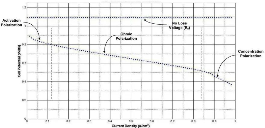
4.4 Activation Loss ... 65
4.4.1 Activation Polarization ... 65
4.4.2 Cross-Over and Internal Current Loss ... 66
4.4.3 Total Activation Loss ... 67
x
4.6 Ohmic Loss ... 69
4.7 Parasitic Losses ... 70
4.8 Scaling Cell Representation to Stack Level ... 72
4.8.1 Load Dependent Temperature Change ... 73
4.8.2 Stack Temperature ... 74
4.9 Operation of Fuel Cell Power Module ... 75
4.9.1 Operational Analysis of Fuel Cell Power Module... 76
4.9.2 Revised Electric Model ... 78
4.9.3 Benefits of the Revised Electric Model ... 79
4.9.4 Electric Model Implementation ... 79
4.9.5 Experimental Results ... 81
4.9.6 Model Comparison and Discussion ... 81
4.10 Ideal Fuel Cell Model ... 84
4.10.1 Simulated Operation of Fuel Cell ... 84
4.10.2 Model Auxiliary Losses Support ... 85
4.11 References ... 86
5 SYNCHRONIZATION ... 88
5.1 Synchronization Techniques ... 88
5.2 dq-PLL ... 89
5.3 Selection of Synchronization Source ... 92
5.3.1 Black Start ... 93
5.3.2 Island ... 94
5.3.3 Grid ... 95
5.3.4 Open-Loop ... 95
5.4 Frequency Tracking ... 95
5.5 Tracking Technique ... 96
xi
5.7 System Startup ... 99
5.8 References for Island Operation ... 99
5.9 Island to Grid Transition ... 100
5.10 Grid References ... 100
5.10.1 Three Phase PLL ... 100
5.10.2 Phase Calculation ... 100
5.10.3 Verification of Grid Existence ... 101
5.11 Reclosing Sync Algorithm ... 101
5.12 References ... 102
6 MICROGRID CONTROL MODEL DEVELOPMENT ... 103
6.1 Voltage Source Converters ... 103
6.2 Control Objectives ... 104
6.3 Control Variables ... 105
6.4 Simplified Grid Connection ... 106
6.5 Grid Connected Control System Model ... 107
6.5.1 Model Constants and Parameters ... 108
6.5.2 Laboratory Inverter Architecture ... 108
6.5.3 Model Analysis ... 109
6.5.4 Operating Frequency ... 110
6.5.5 The Effects of Transformer and Filter ... 111
6.5.6 DC Voltage Compensation ... 112
6.5.7 VSC Linear Model ... 113
6.5.8 Controller Dynamics ... 113
6.5.9 Disturbance Compensation ... 116
6.5.10 Current Limitation ... 116
6.6 Grid Connected Operation (Current Control) Model ... 116
xii
6.6.2 dq Axis Compensator ... 119
6.7 Island Operation (Voltage Control) Model ... 120
6.7.1 Model Analysis ... 122
6.7.2 Development of Island Model ... 123
6.7.3 Voltage Controller ... 123
6.7.4 Current Controller ... 126
6.8 Microgrid Dual Mode Controller ... 127
6.8.1 Control Signal Transformation ... 127
6.8.2 Dynamic Controller ... 128
6.9 Control System Reference Generation... 129
6.9.1 Reference Currents... 129
6.9.2 References for Island Operation ... 130
6.10 References ... 131
7 TRANSITION BETWEEN MODES OF OPERATION ... 133
7.1 Supervisory Controller Overview ... 133
7.1.1 Supervisor External Interfaces ... 134
7.1.2 Supervisory Reference Generation ... 135
7.1.3 Control Mode Parameters ... 136
7.2 Operating Mode Transitions ... 137
7.2.1 System Start-up ... 137
7.2.2 Support States ... 139
7.2.3 Island ... 139
7.2.4 Grid Connected ... 141
7.2.5 Shutdown ... 143
7.2.6 Restart ... 143
7.3 System Disturbances ... 143
7.3.1 Connection Status Changes ... 144
xiii
7.3.3 Grid Connected Mode Changes ... 144
7.4 Grid Connection Transition Power Flow ... 145
7.5 Control Modes ... 145
7.5.1 Load Following... 146
7.5.2 Curtailment ... 146
7.5.3 Peak Shaving ... 146
7.5.4 Export ... 147
7.5.5 Idle ... 147
7.5.6 Open-Loop ... 147
7.5.7 Forced Island ... 149
7.5.8 Fault ... 149
7.5.9 Black Start ... 149
7.6 Dynamic Controller ... 149
7.6.1 Controller Selection ... 149
7.6.2 Controller Activation ... 150
7.7 References ... 150
8 MICROGRID SIMULATION MODELS ... 151
8.1 AC & DC Sources ... 151
8.1.1 Grid ... 151
8.1.2 Nexa Fuel Cell Module ... 151
8.2 Open-Loop ... 152
8.3 Frequency Reference Generation ... 153
8.4 Current Controller ... 156
8.4.1 Primary Current Control ... 157
8.4.2 Primary Current References ... 158
8.4.3 Current Reference Tracking Performance ... 158
xiv
8.5.1 Independent Reference Generation ... 160
8.5.2 Voltage Regulator... 161
8.5.3 Current Controller ... 161
8.5.4 Voltage Reference Tracking Performance ... 161
8.6 Supervisory Controller ... 162
8.6.1 State Monitor ... 163
8.6.2 Mode Transition Logic ... 163
8.6.3 Supervisory Testing ... 164
8.7 System Start-up and Synchronization ... 165
8.7.1 Synchronization Selection ... 166
8.7.2 Synchronization Evaluation System ... 167
8.7.3 System Start-up Reference Signals ... 170
8.7.4 Microgrid to Grid Synchronization ... 174
8.7.5 Frequency Adjustment... 174
8.7.6 Power Output During Start-up ... 175
9 MICROGRID SIMULATION RESULTS ... 176
9.1 Island and Transition Operation ... 176
9.1.1 Island Operation During Start-up ... 177
9.1.2 Island Start-up to Grid Connection ... 178
9.1.3 Island Operation After Grid Connection ... 180
9.1.4 Island Operation Special Cases ... 185
9.2 Grid Connected Operation ... 186
9.2.1 Curtailment ... 187
9.2.2 Export ... 189
9.2.3 Peak Shaving ... 192
9.2.4 Grid Connected Operation Special Cases ... 193
9.3 Load Performance and Quality ... 194
9.3.1 Power Quality – Ideal Source ... 194
xv
10 MICROGRID LABORATORY SETUP ... 201
10.1 Grid Connection ... 201
10.1.1 Simulated Grid Supply ... 201
10.1.2 Grid Connection Equipment ... 202
10.2 Interconnection Rack / Point of Common Coupling ... 204
10.2.1 Isolator / Disconnect ... 205
10.2.2 Contactor ... 205
10.2.3 Intertie Relay ... 206
10.2.4 Meter ... 207
10.2.5 Fusing Protection ... 207
10.2.6 Breakers ... 209
10.3 Interconnection Control Interface ... 209
10.3.1 Signal Isolation ... 209
10.3.2 Connection State ... 209
10.3.3 Grid Synchronization ... 212
10.4 Inverter Modifications ... 212
10.4.1 Replace MOSFET Driver ... 213
10.4.2 Pulse Signal Conditioning / Driver ... 214
10.4.3 Utilization of the Slave Processor in dSPACE ... 215
10.4.4 New Sensors ... 216
10.5 Control Algorithm Implementation ... 217
10.5.1 dSPACE Real-Time Platform ... 217
10.5.2 I/O Sensor Map ... 219
10.6 Control Model using Physical I/O ... 221
10.6.1 Digital Inputs... 222
10.6.2 Analog Signals ... 223
10.6.3 PWM Pulses ... 223
10.6.4 Control Model ... 225
xvi
10.8 Microgrid Line Impedance ... 226
10.9 References ... 226
11 LABORATORY EVALUATION AND MICROGRID OPERATION ... 228
11.1 Experiment Plan and Setup ... 228
11.1.1 Control Platform ... 229
11.1.2 Simulated Grid Connection ... 230
11.1.3 Experimental Control Algorithm Changes ... 231
11.2 Equipment Validation ... 231
11.2.1 Interconnection Equipment Rack ... 232
11.2.2 Test Equipment ... 232
11.2.3 Power Circuit ... 232
11.2.4 Interconnection Equipment Rack to dSPACE Interface ... 233
11.2.5 Microgrid Power Circuit ... 233
11.3 Open-Loop ... 233
11.4 System Start-Up (Black Start) ... 235
11.5 Island Operation ... 235
11.5.1 Island Frequency Regulation ... 236
11.5.2 Island Voltage Regulation ... 237
11.5.3 Island Load Power Change ... 237
11.5.4 Island Power Quality ... 238
11.6 Synchronization ... 240
11.6.1 Grid Presence Detection ... 241
11.6.2 Island to Grid Connection ... 242
11.6.3 Grid Connection ... 244
11.6.4 Grid Connection to Intentional Island ... 246
11.7 Grid Connected Operation ... 249
11.7.1 Current Change due to Load Change & Reference Change... 249
xvii
11.7.3 Power Quality ... 253
11.8 Island Detection ... 253
11.8.1 Frequency Trip ... 255
11.8.2 Voltage Trip ... 256
11.8.3 Non-Detection Zone ... 260
11.9 Campus Grid Connection Testing ... 261
11.9.1 Campus Grid Connection ... 261
11.9.2 Synchronization ... 262
11.9.3 Export ... 265
11.9.4 Long Term Operation ... 268
11.9.5 Curtailment ... 269
12 COMPARISON BETWEEN SIMULATED AND LABORATORY MICROGRIDS 270 12.1 Simulation vs. Laboratory Operation ... 270
12.1.1 General ... 270
12.1.2 Synchronization ... 271
12.1.3 Island Operation ... 271
12.1.4 Grid Connection Transitions ... 272
12.1.5 Grid Connected Operation ... 272
12.2 Power Quality Comparison ... 273
12.2.1 Power Quality – Ideal Source ... 273
12.2.2 Power Quality – Fuel Cell Source ... 274
12.3 Island Detection ... 275
12.4 Microgrid Evaluation ... 275
13 CONCLUSIONS ... 276
13.1 Contributions ... 277
xviii
LIST OF APPENDICIES
Volume II
14 Appendix A – Basic Power Theory ……….. 280
15 Appendix B – Distributed Generation ………..……… 288
16 Appendix C – Point of Common Coupling ...…………..………. 303
17 Appendix D – Experimental Equipment ………..………... 312
18 Appendix D – Experimental Equipment ………..………... 346
19 Appendix F – Current and Voltage Sensors ………..……… 367
20 Appendix G – System Analysis ………...……… 386
21 Appendix H – Simulation Support ………...……...…… 395
xix
LIST OF TABLES
Table 3-1 IEEE Power Quality Standards ... 41
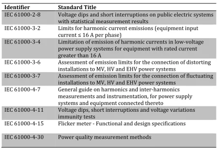
Table 3-2 IEC Power Quality Standards ... 41
Table 3-3 Islanding Standards ... 45
Table 3-4 Interconnection Protection Objectives ... 50
Table 3-5 Protection Functions ... 51
Table 5-1 Synchronization Sources ... 94
Table 5-2 Transformer Turn Ratios ... 95
Table 6-1 Operating Parameters and Component Values... 107
Table 6-2 Control Model Parameters ... 108
Table 7-1 Control Mode Parameters ... 136
Table 8-1 Connection State Constants ... 162
Table 8-2 Control Mode Enumerated Type ... 162
Table 8-3 System Start-up Events ... 169
Table 9-1 Black Start – Island Events ... 177
Table 9-2 Black Start – Connect To Grid Events ... 179
Table 9-3 Island – Loss of Grid Events ... 181
Table 9-4 Island – Loss of Microgrid Events ... 184
Table 9-5 Curtailment Events ... 187
Table 9-6 Export Events ... 189
xx
Table 9-8 Island THD Events ... 194
Table 9-9 Grid Connected THD Events ... 195
Table 10-1 Grid Connection Equipment ... 203
Table 10-2 Interconnection Rack Equipment ... 205
Table 10-3 Replacement Fuses ... 208
Table 10-4 dSPACE Slave I/O Connector Map ... 216
Table 10-5 Digital Input Interface ... 219
Table 10-6 Analog Input Interface ... 220
Table 11-1 Peak Shaving Power Flow (Reference = 1W) ... 249
Table 11-2 Peak Shaving Power Flow (Reference = 800W) ... 249
Table 11-3 Island Detection ... 261
Table 12-1 Ideal Source Based Microgrid Power Quality Comparison ... 273
xxi
LIST OF FIGURES
xxii
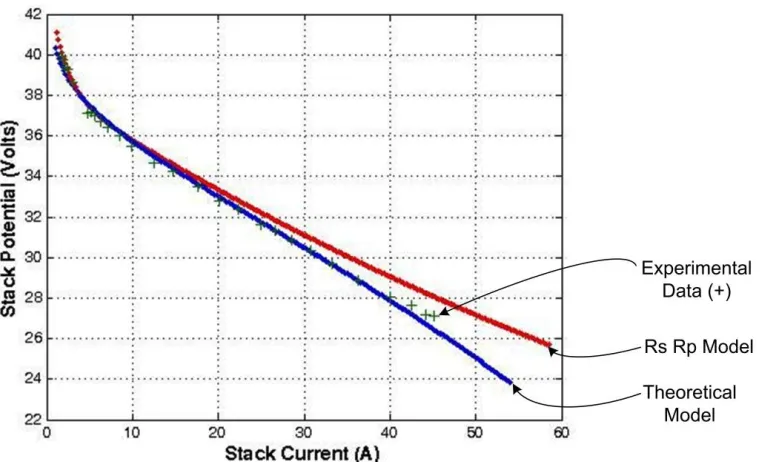
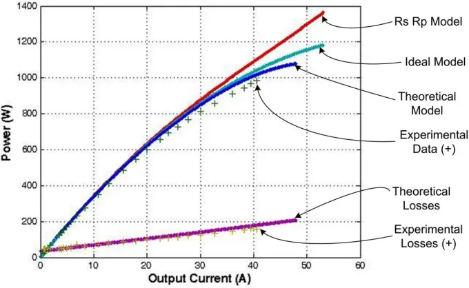
Figure 4-9 Theoretical Power vs. Output Current ... 71 Figure 4-10 Auxiliary Power Loss Model Comparison ... 71 Figure 4-11 Fuel Cell Stack Temperature Model to Actual Comparison ... 74 Figure 4-12 Fuel Cell Characterization Test Setup ... 75 Figure 4-13 Comparison of Electric Ciruit Models ... 77 Figure 4-14 Implementation of the Revised Electric Model ... 79 Figure 4-15 Measured Fuel Cell Model Output ... 80 Figure 4-16 Calculated Module Auxiliary Losses ... 80 Figure 4-17 Calculated Series Resistance (rs) ... 80
Figure 4-18 Calculated Parallel Resistance (rp) ... 80
xxiii
xxiv
Figure 8-4 Comparison Between Simulation and Laboratory Inverter under Open-Loop Control ... 154 Figure 8-5 Simulated Synchronization References from Each Sync Source ... 155 Figure 8-6 Current Control System ... 156 Figure 8-7 Transformer Primary to Secondary Voltage Phase Shift ... 157 Figure 8-8 Comparison of Primary to Secondary Voltage and Current ... 157 Figure 8-9 Current Control Real Power (W) and Reactive Power (var) ... 158 Figure 8-10 Primary Current Reference Tracking ... 159 Figure 8-11 Voltage Control System... 160 Figure 8-12 Frequency and Voltage Regulation by the Voltage Controller ... 160 Figure 8-13 Primary Voltage Reference Tracking ... 161 Figure 8-14 State Island Transition Testing ... 163 Figure 8-15 State Monitor ... 164 Figure 8-16 Finite State Machine Implementation (State Flow) ... 165 Figure 8-17 Frequency Generation ... 166 Figure 8-18 Synchronization Test Network ... 168 Figure 8-19 Reference Frequency ωt (rad/s) During Black Start ... 170
xxv
xxvi
xxvii
xxviii
xxix
DEFINITIONS AND NOMENCLATURE
The definitions for many of the technical terms can be found in the referenced standards and legislation. The definitions provided here are for information purposes only. Please refer to the following documents for legal definitions:
Canadian Electric Code (Section 0) [i] IEEE 1547 [ii]
CSA Standard C22.2 No. 107 [iii]
Definitions
Ancillary Services – Those services necessary to support the transmission of electric power from seller to purchaser given the obligations of control areas and transmitting utilities within those control areas to maintain reliable operations of the interconnected transmission system (US Federal Energy Regulatory Commission).
Backfeed – The inadvertent transfer of energy between power sources.
Black Start – The process of restoring a power station to operation without relying on the external electric power transmission network.
Disconnecting Means – A device, or group of devices, or other means by which the conductors of a circuit can be disconnected from their source of supply.
Distributed Generation (DG) – Generation of electricity by facilities that are sufficiently smaller than central generating plants so as to allow interconnection at nearly any point in the power system [iv]. Electric generation facilities are connected to a distribution system through the point of common coupling. Distributed generation is a subset of Distributed Resources.
Distributed Resource (DR) – Sources of real electric power that are not directly connected to the bulk power system. It includes both generators and energy storage technologies.
xxx
Inverter – An electrical device that converts direct current (DC) to alternating current (AC); the converted AC can be at any required voltage and frequency with the use of appropriate transformers, switching, and control circuits.
Island – A condition in which a portion of an area electric power system (EPS) is energized solely by one or more local EPSs through the associated point of common couplings (PCC) while that portion of the area EPS is electrically separated from the rest of the area EPS.
Islanding – The operation of a utility-interconnected inverter and part of the utility load while isolated from the remainder of the electric utility system.
Isolating Switch – A switch intended for isolating an electric circuit from the source of power. It has no interrupting rating and is intended to be operated only after the circuit has been opened by some other means.
Microgrid - The CERTS Microgrid concept is the aggregation of loads and micro-sources operating as a single system providing both power and heat. The majority of the micro-sources must be power electronic based to provide the required flexibility to insure operation as a single aggregated system. This control flexibility allows the CERTS Microgrid to present itself to the bulk power system as a single controlled unit that meets local needs for reliability and security. [v]
Point of Common Coupling (PCC) – Will be used to refer to the point where the electrical facilities or conductors of the Wire Owner are connected to the Power Producer’s facilities or conductors, and where any transfer of electric power between the Power Producer and the Wire Owner takes place.
Static Transfer Switch – An electrical switch that reconnects electric power source from its primary source to a standby source. Switches may be manually or automatically operated. An Automatic Transfer Switch (ATS) is often installed where
a backup generator is located, so that the generator may provide temporary electrical power if the utility source fails.
Smart Meter – Smart Meters measure and store data about when customers use electricity as the foundation for Time-of-Use (TOU) billing.
Utility-interconnected Inverter – An inverter intended for use in parallel with, and may deliver power to, a supply authority.
Abbreviations
AC Alternating Current
xxxi ATS Automatic Transfer Switch AWG American Wire Gauge CEC Canadian Electric Code
CERTS Consortium for Electric Reliability Technology Solutions CHP Combined Heat and Power
CSA Canadian Standards Association CT Current Transformer
DAC Digital to Analog Converter DAQ Data Acquisition
DC Direct Current
DER Distributed Energy Resource DG Distributed Generation DSC Distribution System Code EMI Electro Magnetic Interference EMS Energy Management System EPS Electricity Power System ESA Electrical Safety Authority FC Fuel Cell
FSM Finite State Machine GHG Green House Gases HV High Voltage
IEA International Energy Agency
IEC International Electrotechnical Commission IEEE Institute of Electrical and Electronics Engineers IESO Independent Electricity System Operator IPP Independent Power Producer
KCL Kirchhoff Current Law KVL Kirchhoff Voltage Law
LabVIEW Laboratory Virtual Instrumentation Engineering Workbench LDC Local Distribution Company
xxxii NDZ Non Detection Zone
NI National Instruments
NIST National Institute of Standards and Technology NRCan Natural Resources Canada
NSERC Natural Science and Engineering Research Council OEB Ontario Energy Board
OESC Ontario Electrical Safety Code
OFCRIN Ontario Fuel Cell Research and Innovation Network OPA Ontario Power Authority
ORF Ontario Research Fund PCC Point of Common Coupling
PEM FC Proton Exchange Membrane Fuel Cell PI Proportional-Integral
PLL Phase Locked Loop PT Potential Transformer PU Per Unit
PV Photovoltaic
PWM Pulse Width Modulation RMS Root Mean Square
SCADA Supervisory Control and Data Acquisition T&D Transmission and Distribution
TOU Time Of Use
UL Underwriters Laboratory UWO University of Western Ontario TDD Total Demand Distortion THD Total Harmonic Distortion UPS Uninterrupted Power Supply VI Virtual Instrument
xxxiii
Nomenclature
Active Control Mode Current operating mode used by the system
Connection Information Status information from the interconnection rack (PCC)
Connection State Logical OR of the Connection Information
Control Mode User selected operating mode
Iabc / IP / Ip abc / Iprimary The current passing into the primary side of the transformer
Ip-dq / Ipd / Ipq dq reference frame for the primary current (IP)
Ip-dq ref / Ipd ref / Ipq ref Current control reference signal (Primary)
IS / Isecondary The current leaving the secondary side of the transformer
Isd / Isq dq reference frame for the secondary current (IS)
Iabc-L The current delivered to the load
Id-L / Iq-L dq reference frame for the load current (ILoad)
IDC The DC current entering the inverter
Mabc Modulation signal
Mdq / Md / Mq dq reference frame for the modulation signal (Mabc)
PDG / QDG Inverter output power
PLoad / QLoad Load power consumed
Pref / Qref Supervisory Power (Watts) and Reactive (Var) Reference
PWM / Pulses Pulse Width Modulation Signal
V2 PCC Voltage on the Grid Side of the Disconnect
VDC The DC voltage across the DC link capacitors
VG / VGrid The voltage of the grid / utility
Vabc / VP / Vp abc / Vprimary The voltage at the input to the transformer (Primary)
Vp-dq / Vpd / Vpq dq reference frame for the primary voltage (VP)
Vp abc ref Voltage regulation reference signal (Primary)
Vp-dq ref / Vpd ref / Vpq ref dq reference frame for the voltage regulation (Vp abc ref)
VS / Vsecondary The voltage at the output of the transformer (Secondary)
Vsd / Vsq dq reference frame for the secondary voltage (VS)
Sync Source Selected synchronization source used to determine ωt
System Parameters Fixed operating parameters (Maximum Generation, etc.)
User Settings Enable and Disable control of grid connected functionality
xxxiv
International System of Units
The following are the International System of Units (SI) related to power systems:
s second Time A ampere Current V volt Voltage W watt Real Power VA volt-ampere Apparent Power var var Reactive Power
Ω ohm Impedance / Resistance H henry Inductance
F farad Capacitance
Copyrights & Trademarks
Designations used by companies to distinguish their products are often claimed as trademarks. All brand names and product names used in this work are trade names, service marks, trademarks or registered trademarks of their respective owners. Product specifications are believed to be accurate at the time of purchase of the respective items.
References
[i] CSA Standard 22.1-02, Canadian Electric Code, Part I, Canadian Standards Association, 19th Edition, 2002
[ii] IEEE Standard for Interconnecting Distributed Resources with Electric Power Systems, IEEE 1547-2003, July 2003
[iii] CSA Standard 22.2, No. 107.1-01, General Use Power Supplies, Canadian Standards Association, 2001
[iv] G. Pepermans, Distributed Generation: definition, benefits and issues, Energy Policy 33, 2005, pp 787 – 798
1 INTRODUCTION
The ability to connect a microgrid to the grid (distribution network) is an important step in the development and evolution of the modern power system. The power system is changing due to pressures from regulators, customers and the aging of the infrastructure. The introduction of microgrids to the power system is being enabled by the evolution in power electronic interfaces and their control capabilities. This chapter will explore the factors contributing to this revolution in the power system and the scope of this research.
1.1 Motivations
1.1.1 Evolving Power System
Power systems around the world are undergoing a period of change. In Ontario, government directives to promote the use of renewable energy and the introduction of time-of-use energy usage charges are two of the important initiatives. This direction is defined by the new ‘Green Energy Act’ [1.1] and the introduction of new Smart Meters installed for every customer in the province [1.2]. The power infrastructure is also facing challenges of growth and aging which can result in decreased reliability especially during periods of stress on the network. Consumers are looking for solutions to allow the integration of renewable sources and more effective tools to control energy costs. At the same time most consumers are demanding higher reliability and higher power quality.
1.1.2 Microgrids
must be power electronic based to provide the required flexibility to ensure operation as a single aggregated system. This control flexibility allows the CERTS Microgrid to present itself to the bulk power system as a single controlled unit that meets local needs for reliability and security. The inverter controller provides the means for advanced control strategies to be utilized. Microgrids often include controllable loads and storage elements. A microgrid is well suited for integrating a renewable source into the grid [1.4].
A microgrid can provide a solution to the problems faced by the consumer as well as provide support to the local distribution network in the form of Ancillary Services [1.3]. Customers with unreliable grid connections require a new power delivery system to meet local demand and generation including renewable, traditional and alternative generators as well as power exchange with the grid. The loss of the grid connection may be a long duration outage during severe weather conditions or serious transmission problems. Many of these customers have critical loads such as livestock operations that require constant un-interrupted power. A microgrid approach provides a solution to provide reliable quality power with the flexibility to adapt to changes that are coming to the power system landscape.
1.1.3 Smart Grid
The province organized the Ontario Smart Grid Forum [1.5] to help define the evolution of the grid in Ontario. The findings from the Forum can be found in their report “Enabling Tomorrow’s Electricity System” [1.6]. The report provided a definition of the Smart Grid:
The report also identifies microgrids as playing a role in the development of the smart grid. The control capabilities of the microgrid mesh well with the needs of the smart grid. The application of microgrids in Ontario is identified in the report as requiring research and further development.
One of the standards bodies active in defining the shape of the new Smart Grid in the United States is the National Institute of Standards and Technology (NIST). Their vision of the evolution of the Smart Grid can be seen in their roadmap document [1.7]. Microgrids also play an important role in their vision for the Smart Grid.
1.1.4 Applications Utilizing Microgrids
Many changes to the power system are currently underway and more changes are on the near-term horizon. The traditional water fall model of the power system is not well suited to adapt to changes. Reverse power flow due to the incorporation of renewable sources (PV & wind) in the distribution network will affect many aspects of the power system. The way power is being consumed is also changing with the introduction of plug-in-electric vehicles; controllable ‘smart’ loads; and the wider utilization of energy storage devices to store energy from non-peak times and then discharge it at peak times. Many of these changes are occurring at the distribution level affecting the local distribution companies. Many of the challenges facing the power system are located at the boundary between the customer and the distribution network. The microgrid concept provides a level of intelligence to allow customers to interact with the power system at this critical interface.
1.2 Problem Statements
1.2.1 Grid Connection vs. Island Operation
The control challenge for inverter operation is that different behaviors are required when the grid is present and when it is absent (island). The controller must adopt different control schemes (algorithms) depending on the state of the grid connection. While connected to the grid, the inverter is responsible for injecting power to meet the control objectives defined by the operator following the grid frequency and voltage levels. Power delivered to the grid must be at unity power factor and not interfere with normal distribution network operation. When the inverter is disconnected from the grid, the only objective for the inverter is to service the local load maintaining the local frequency and voltage levels in the microgrid.
1.2.2 Islanding Detection
One of the critical aspects of microgrid operation is the detection of islanding conditions. The island detection scheme needs to minimize the region where the microgrid operates under assumed grid connected conditions when the grid is no longer present. The detection of an island condition requires the transition to island operation. Related to islanding detection is the need to provide a protection scheme to protect both the generators (and load) and the grid.
1.2.3 Ride-Through Capability
When the state of the grid connection changes, the controller must switch between operation modes without the interruption of power delivery to the load and maintain power quality. The controller must adapt automatically such that there is no change to the power being delivered to the load. This means that there cannot be: power droop (brown out), interruption (transfer switch), and no introduction of disturbances (transients).
1.2.4 Control Algorithm
switching between island and grid connected operation, in particular obtaining synchronization of island operation with the grid to allow the protection system to re-close. Another issue resolved is the conflicting control objectives between island and grid connected operation. The conflict results in saturation of controllers that has the potential to introduce large disturbances during operating mode transitions.
1.2.5 Interconnection
The interconnection provides the interface between the microgrid and the electrical distribution system. This interface is strictly regulated to ensure the safety of the system and protection of people and property. The operation of the microgrid when operating isolated from the grid requires the system to meet local load demand.
1.2.6 Unregulated Fuel Cell
A fuel cell power module provides a controllable source that can be dispatched. The output from the PEM fuel cell power module is unregulated DC. As the current increases, the output voltage from the power module decreases. The decreased voltage is due to internal losses and the parasitic losses of the balance of plant equipment (cooling fans) that draw power from the fuel cell output. As well, the fuel cell output changes with changes in the stack temperature.
1.3 Objectives
The following are the objectives for this research:
1. Model a microgrid operation in both island and grid connected modes for a PEM fuel cell power module based system. Demonstrate a working interface between the utility and the lab microgrid and validate the simulation models by laboratory experiments.
2. Evaluate the microgrid performance and power quality using Total Harmonic Distortion (THD) targets of:
b. THD under 8% for Current;
c. No frequency drift while operating as an island; and
d. Maintain quality targets under the different modes of operation. 3. Validate the operation of the microgrid under four modes of operation and
under different load profiles: a. Island – Load Following;
b. Grid Connected – Peak Shaving; c. Grid Connected – Curtailment; and d. Grid Connected – Export.
4. Evaluate the disturbances introduced when switching control modes.
5. Measure the performance of the passive islanding detection utilizing the Intertie Relay protection functions.
1.4 Scope of Research
The focus of the research is on the microgrid control system with respect to the interactions between the grid and the microgrid during grid connected operation. The rules around the interconnection are explored as well as the operation of the microgrid while connected and disconnected (island) from the grid. A particular focus is on the transition between connected and disconnected states.
Some of the areas that will not be investigated as part of this research includes:
- Not utilizing the bidirectional nature of the single stage inverter – No
storage elements are included in the microgrid network;
- Advanced islanding operation to support load shedding activities;
- Enhanced protection to utilize the advanced features of the a protective
relay;
1.5 Contributions
The following are the major contributions resulting from this research:
- Development of control models for a grid connected single stage inverter
in Matlab Simulink using SimPowerSystem.
o Voltage Controller (Island Operation)
o Current Controller (Grid Connected Operation)
o Synchronization Process for transitioning between modes of
operation
- Develop a simple electric model for a PEM fuel cell power module that
incorporates internal losses and losses for auxiliary systems and temperature effects;
- Simulation of a simple microgrid operating to achieve various power
production modes when in both grid connected and in islanding states;
- Construction of a laboratory grid connected microgrid meeting all
appropriate standards and codes;
- The control algorithms are translated into versions that can operate in
real-time on the dSPACE platform. The real-time performance of the models are validated and compared to the simulation results; and
- Test equipment setup and configuration for monitoring the operation of
the microgrid.
1.6 Challenges
1.6.1 Standards
UL) of equipment and devices. The applicable standards are listed in Section 3.2.1. Another of the important standards bodies is the International Electro-technical Commission (IEC) which develops rules adopted by most countries [1.10].
1.6.2 Laboratory Microgrid
One of the challenges of this research is the requirement to construct an experimental microgrid. The laboratory microgrid is simplified by having only a single generator, single load and the connection to the grid. The university campus distribution network will act as the grid. The two other important elements are the inverter with the control algorithms and the Point of Common Coupling (PCC) which follows all of the interfacing requirements specified by the local distribution company. The experimental setup is used to validate the control algorithms under different real world scenarios.
1.6.3 Power Quality
One of the principal ways to measure the operation of a microgrid is by observing the power quality. Power Quality for a microgrid is seen as the sum of the voltage quality and current quality where voltage quality is of first concern [1.11].
Voltage Quality: is concerned with deviations of the voltage from the ideal. The ideal voltage is a single frequency sine wave of constant amplitude.
Current Quality is concerned with the deviation of the current from the ideal. The ideal current is a single frequency sine wave of constant amplitude, with the additional requirement that the current sine wave is in phase with the voltage sine wave.
1.7 Organization
Chapter 2: Microgrid Background
The experimental microgrid provides a connection between the grid, a local load and local generation (Fuel Cell). When a microgrid is connected to the main utility, special consideration must be given to safety, standards and protection requirements. To support the operation of the microgrid, different support systems are required including: Protection, Supervisory Control, Dynamic Control and a power electronic interface consisting of an inverter, filter and transformer. The high level operation of each component is described.
Chapter 3: Microgrid Operation
The main purpose of the microgrid is to control the power flow in the local power network. The behavior of the microgrid is dependent on the operating state: Island or Grid Connected. The modes of operation for the microgrid system are reviewed including the parameters required for each mode. The controller governing each mode of operation needs to consider a variety of factors to meet the system objectives. Fundamentally, the control algorithm must accommodate the issue of power quality and manage the concern of island detection.
Chapter 4: Fuel Cell Electric Model
Chapter 5: Synchronization
An islanded microgrid requires the ability to connect to the grid. For the connection to occur the voltage, frequency and phase of the island system must be close to those of the grid. There are numerous synchronization algorithms that provide microgrids the ability to adjust their operation to be in-phase. The synchronization algorithm must operate well in the presence of grid disturbances (harmonics) and grid imbalance. The algorithm must be responsive to changes in the grid reference signal. It has been demonstrated that a phase-locked loop with a dq transformation (dq-PLL) is a suitable technique for grid connection applications such as wind turbines, PV and fuel cell systems.
Chapter 6: Microgrid Control Model Development
The control of a microgrid when connected to the power system is based on advances in power electronics and the corresponding control theory in the utilization of a rotating frame of reference such as the Clark-Park transformations. A simplified grid connection model is described. The control algorithms are discussed for both the grid connected (Current Control Mode) and island (Voltage Control Mode) operation. An aggregated controller is presented to demonstrate the simultaneous operation of both controllers.
Chapter 7: Transition Between Modes of Operation
controller are attempting to control the system to meet their independent control objectives.
Chapter 8: Microgrid Simulation Models
The approach to building the simulation model is to construct the components of the system separately and integrate the working models into the full system model. The full simulation is composed of the following control components: Phase Locked Loop, Power Electronic Interface (Open Loop Model), Fuel Cell Source, Current Controller, Voltage Controller, Supervisory Controller, Frequency Tracking and Black Start including Synchronization. The models are evaluated individually as well as collectively to meet the defined control objectives.
Chapter 9: Microgrid Simulation Results
The results from the simulation of the complete microgrid are presented. The controller is validated under the different operation modes and the transitions between each of the modes are analyzed. The microgrid is operated under different load levels and under different desired output references. The power quality is examined. A series of scenarios are simulated to examine the models under different real-world situations.
Chapter 10: Microgrid Laboratory Setup
The construction of the laboratory microgrid requires assembly of some specialized equipment and the modification of an existing experimental inverter. The grid connection consists of three sub-systems: the physical grid connection, an interconnection rack (PCC) and the power electronic inverter. The interconnection rack and inverter are interfaced to the real-time control system. The microgrid controller connected to the inverter has been modified to incorporate information from new inverter sensors and interconnection rack sensors.
Chapter 11: Laboratory Evaluation and Microgrid Operation
equipment is validated in an incremental fashion to ensure each part is constructed and configured correctly. Once the equipment and control algorithms are tested, the completed system is connected to the grid (campus distribution network). The operation of the control algorithms has been validated on the physical hardware under different test scenarios.
Chapter 12 and Chapter 13: Comparison Between Simulation and Experiment Microgrids with Conclusions
The final two chapters show a comparison between the model that has been simulated in the MatLab Simulink environment and the laboratory implementation of the model. The simulation and implementation are compared under both grid connected and islanded operation. As well, both systems are measured in terms of how well each system meets the design objectives. Finally, the research is reviewed with a highlight of the contributions and the follow-up research opportunities are identified.
Appendixes
The appendixes contain background information on distributed generation and the requirements for the point of common coupling. The detailed technical specifications of the equipment used in this research including the details of the sensors used in the inverter and the new gate drivers are provided. The specifications for the test equipment are listed. The configuration settings used in the network interface, power meter and intertie relay are recorded. The components developed to support the simulation work are described as well as a description is provided for the test environment used to validate the laboratory experiments.
1.8 References
[1.1] Ontario Green Energy Act. Accessed: Oct. 14, 2010
http://www.mei.gov.on.ca/en/energy/gea/ [1.2] Ontario Smart Meters Accessed: Oct. 14, 2010
[1.3] J. Lopes, N. Hatziargyriou, J. Mutale, P. Djapic, N. Jenkins, Integrating distributed generation into electric power systems: A review of drivers, challenges and opportunities, Electric Power Systems Research, No. 77, 2007, pp. 1189-1203 [1.4] R. Lasseter, Integration of Distributed Energy Resources – The CERTS MicroGrid
Concept, April 2002, LBNL-50829
[1.5] Ontario Smart Grid Forum (IESO) Accessed: Oct. 14, 2010 http://www.ieso.ca/imoweb/marketsandprograms/smart_grid.asp
[1.6] J. Singer, Enabling Tomorrow’s Electricity System, Ontario Smart Grid Forum Report, February 2009
[1.7] NIST Framework and Roadmap for Smart Grid Interoperability Standards, Release 1.0, National Institute of Standards and Technology, US Department of Commerce, September 2009
[1.8] M. Kazmierkowski, L. Malesani, Current Control Techniques for Three-Phase Voltage-Source PWM Converters: A Survey, IEEE Trans. on Industrial Electronics, Vol. 45, No. 5, October 1998, pp. 691-703
[1.9] J. Neu, S. Martel, Connecting MicroPower to the Grid, microPower Connect, 2nd
Edition, Natural Resources Canada, 2006
[1.10] S. Papathanassiou, N. Hatziargyriou, Technical Requirements for the Connection of Dispersed Generation to the Grid, IEEE PES Meeting, Vancouver, August 2002 [1.11] M. Bollen, Review: What is power quality?, Electric Power Systems Research 66,
2 MICROGRID BACKGROUND
The experimental microgrid provides a connection between the grid, a local load and local generation. When a microgrid is connected to the main utility, special consideration must be given to safety, standards and protection requirements. To support the operation of the microgrid, different support systems are required including: Protection, Supervisory Control, Dynamic Control and a power electronic interface consisting of an inverter, filter and transformer. The high level operation of each component is described.
2.1 Microgrids
The successful integration of microgrids into the distribution system is dependent on the control of the interface between the microgrid and the utility grid. The interaction with the utility must meet high quality standards to ensure that power transferred over the interface (PCC) and any disturbance attributed to the microgrid does not affect utility customers and utility operation. The interconnection is governed by codes and standards covering the physical connection. Current standards require that all local generation de-energize (stop generation) when the local grid connection is lost. To overcome the problems associated with island operation an advanced control scheme is required to allow safe operation of the generators when the grid connection is lost. This research will demonstrate how a microgrid can safely operate when both connected to the grid and while disconnected (island).
where continued power delivery to critical loads is required. One important feature of grid-connected microgrids is the ability of the microgrid to seamlessly disconnect and reconnect to the grid following strict rules. The ability of the inverter to provide continuous service to local critical loads is known as ‘ride-through’ capability or providing an uninterrupted power supply (UPS) capability. A flexible inverter control scheme is required for grid connected operation to operate under different operating scenarios such as peak shaving, curtailment and islanding. Each mode of operation requires a modification to the control scheme to meet the objectives of each mode.
2.1.1 Microgrid and Distributed Generation
A microgrid is a specialized form of Distributed Generation (DG). Not all DG can be considered a microgrid. The difference in the microgrid is in the local power management capabilities provided by the intelligent power electronic interfaces. Most microgrids are not power producers as much as they remove load from the grid through supplying power to the local loads. In these cases the microgrid is treated as a ‘smart’ load with some reverse power flow capacity. When a microgrid is consistently generating a large amount of power greater than its local loads it becomes more of a DG application and will be treated by the system operator as a generator. The difference in the treatment of the microgrid can be seen in the administrative rules that are applied by the local distribution company with regards to metering, billing, dispatch, protection and autonomy [2.1].
Using London Hydro as an example, the primary distribution system has two voltage levels: 27.6 kV and 13.8 kV. All supply feeders are arranged to run radial with open points between interconnections where practical. These feeders supply distribution transformers either directly or through 4.16 kV or 8.32 kV step-down sub-distribution systems. London Hydro’s secondary supply voltages are:
The laboratory microgrid will be implemented on a 120/208Y volt, three phase, 4 wire system.
2.1.2 Classifications of LV Microgrid Applications
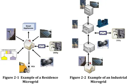
The applications for microgrids can be divided into the following general types: Residence Microgrids; Utility Microgrids; Commercial and Industrial Microgrids; and Remote Microgrids [2.2].
2.1.2.1 Residence Microgrid
Microgrids are a good fit with the movement towards smart homes that have Energy Management Systems (EMS) that integrate all of the smart appliances with sources of generation. The provision of a controllable interface to the distribution system that integrates all local generators and smart loads together is the basic definition of a microgrid. The microgrid operates to minimize costs considering factors such as time-of-use energy pricing and strategies for utilizing available storage and generation. An example of a residential microgrid can be seen in Figure 2-1.
Figure 2-1 Example of a Residence Microgrid
2.1.2.2 Utility Microgrids
Microgrids can be implemented on an entire feeder or partial feeder of a distribution substation. The microgrids can meet local load growth and manage congestion in the network and utilize large DG sources (wind farms, biogas, storage, etc.). The ability to operate parts of the network as distinct islands is useful during maintenance activities and other disturbances while maintaining power delivery to the end customers. Additional services become a possibility for utility microgrids such as CHP (district heating and cooling) and ancillary services.
2.1.2.3 Commercial and Industrial Microgrids
For customers with critical and sensitive loads, microgrids can be used to provide reliable power. Large customers with multiple loads (shopping centre, university campus, industrial plant) can benefit from having full control over their power system by implementing a microgrid. End users are provided with tools to maintain their own power quality and availability when the utility supply does not meet their needs. As well, the customer can utilize energy savings through available power discount options such as peak shaving, curtailment and the integration of renewable generation. An example of a campus microgrid is shown in Figure 2-2.
2.1.2.4 Microgrids for Remote Communities
Many remote communities have either a weak connection or no connection at all to a central grid. These communities require an infrastructure that can operate without the support from the central grid. A microgrid is a good option for these communities to allow the integration of renewable sources and to control the entire remote network.
2.1.3 Benefits of Microgrids
2.1.3.1 Microgrid Behaviour
Good Citizen – complies with all grid rules and does no harm to the grid; able to meet its own energy demand; no export of power; helps to reduce local network congestion.
Ideal Citizen – improves on Good Citizen by also participating in the energy markets while meeting all standards.
Model Citizen – improves on Ideal Citizen by providing support to the local network through exporting energy for ancillary services; congestion relief and local network support.
2.1.3.2 Local Distribution Network
Microgrids can improve the technical performance of a local distribution network by [2.3]:
- Energy loss reduction due to decreased line power flows (utilizing local
generation);
- Minimum of voltage fluctuation by reactive power control;
- Relief of peak loading on constrained networks by utilizing local
generation for demand management;
- Improved reliability through islanding capabilities of the microgrid; and - Power management to ensure that local loads receive reliable power.
The coordination of multiple microgrids becomes an important consideration in the system operation to realize local distribution network improvements.
2.1.3.3 Market Participation
feed-in tariff (FIT) program. Microgrids also can play a role feed-in the aggregation of DG sources under a centralized controller.
2.1.3.4 Building Energy Management System
The Energy Management System (EMS) can make decisions on power generation and on heating or cooling (CHP). The decision can be based on: local demand, weather, the price of electricity, fuel costs, storage levels and future demand predictions. Generation sources that are integrated with buildings are an important component of the building EMS of the future. The ability of the EMS to utilize local generation allows for the operation of cost saving strategies such as peak-shaving, power and waste heat management, centralized load management, and power selection based on cost, contract, availability, and system objectives [2.5]. The microgrid concept is well suited for this type of application.
2.1.3.5 Integration of Multiple Sources
Micro-generation technologies such as micro-turbines, photovoltaic, fuel cells, wind turbines, and storage with a power rating ranging up to hundreds of kilowatts can be connected directly to the low voltage (LV) networks. These micro-generators are located at the customer load and can be used to enhance the LDC reliability and quality. The technical challenge of a microgrid with multiple energy sources is the coordination of the sources. As well, the intermittent nature of renewable sources is a challenge for system operation and coordination of generators. When each generator in a microgrid is equipped with droop based active and reactive power controls along with an internal voltage regulator, the microgrid can also meet the needs of dynamic changes within it [2.6].
2.1.3.6 Environmental Benefits
that operate to supply peak demand which are often heavy polluters from fossil fuels.
2.2 Microgrid Operation
The connection of a microgrid to the utility/grid requires consideration of many important factors. The interconnection is governed under various rules and regulations of the local electrical code. These rules are based on international standards with a focus on the protection of the power infrastructure, equipment and the people working on these systems. The interconnection must implement a protection scheme to ensure that the microgrid is a ‘good citizen’ [2.7] and follows all of the rules defined by the local distribution company.
2.2.1 Essential Components
A microgrid power system has two critical components for operation: the static switch and the micro-source [2.5].
2.2.1.1 Static Switch
The static switch controls the state of the grid connection to force the microgrid into autonomous island mode when the microgrid is separated from the main grid. This separation is typically performed when a disturbance is detected on the grid connection. The microgrid will reconnect to the grid on the re-closing of the static switch when the conditions causing the separation have been cleared. The grid re-connection can only be completed when the voltage, frequency and phase angles of the microgrid match those of the grid at the connection point.
2.2.1.2 Micro-Source
adequate power delivery. The micro-sources will follow the command of the supervisory controller while connected to the grid, typically under a current control mode to deliver a specified amount of power.
2.2.2 Microgrid Control
A microgrid should be able to seamlessly isolate itself from the grid and quickly switch the operating mode. It is required that reactive and real power be independently controlled. The microgrid must be able to meet the dynamic needs of the loads without requiring information from the loads. Micro-sources must be independently controlled and allow sources to be added and removed when necessary [2.5]. Advanced control techniques are implemented in power electronics and are often required to integrate storage and renewable energy sources.
From a control perspective, grid connected operation and island operation are vastly different and require different strategies. In a grid connected operation, the grid provides a reference for both voltage and frequency. In an island operation, the microgrid is responsible for its own references as well as managing generation to meet load requirements. A common control strategy in island operation is to implement droop control to coordinate sources [2.8, 2.9] against load to form a balanced operation. The island controller also needs to consider the condition of black start (initial start-up without the grid being present) and the eventual connection to the grid [2.10, 2.11].
2.2.3 Standards and Guidelines
MicroPower Connect Interconnection Guideline: For inverter based
micro-distributed resource (DER) systems connected to 600 volt or less distribution system, Version 8, July 2003
Electrical Guidelines for Inverter-Based Micro-Generating Facility (10
KW and Smaller), ESA-SPEC-004, April 2010
The interconnection requirements can be organized into the following three categories: general specifications and requirements, safety and protection requirements, and power quality requirements. The main goal of the requirements is to ensure the safety of personnel, the public and the power system. These goals are reflected in the requirement for all interconnected microgrids to have compliance with national electric codes and standards [2.12]. The standards are listed in Appendix B.
2.2.4 Interconnection Protection
One of the biggest changes to the distribution system is the introduction of distributed generation (DG). One of the drivers behind this movement is the need to integrate renewable energy sources into the distribution system. Traditional protection schemes used is the distribution system need to be re-evaluated with the integration of DG associated with customer loads. The interconnection protection varies widely depending on factors such as: generator size, point of interconnection to the utility system (distribution or sub-transmission), type of generator (DC, synchronous, asynchronous) and interconnection transformer configuration. Newer DG systems are utilizing electronic power converters which results in special consideration for DG protection. The impact of DG on existing systems must be examined through detailed simulations and protection studies.
2.2.5 Safety
campus distribution system must be considered in all aspects of the interconnection and bus designs. The reality of the laboratory back-feeding power into the building must be considered and all precautions taken to ensure that this is identified at the connection point and maintenance and research personnel are informed and trained on lock-out/tag-out procedures to be taken when working on the building and laboratory electric systems.
2.3 Laboratory Microgrid
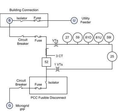
The microgrid used for this research is a simple configuration consisting of one source, one local load and a connection to the grid as seen in Figure 2-3.
Figure 2-3 Laboratory Microgrid
2.3.1 Grid
2.3.2 Fuel Cell
The fuel cell is the primary generator (power source) in the microgrid during island operation. The fuel cell generates an un-regulated DC voltage that is transformed into three phase AC by the inverter. One of the principle concerns of a power system involving a fuel cell power system is that the output of the system is DC at a very low voltage. As well the controller needs to accommodate the dropping voltage characteristic of the fuel cell with the increase in load current. The fuel cell is also characterized by a slow transient response [2.13].
2.3.3 Inverter
The intelligence in the interconnection system is found in the inverter. This device implements algorithms that control the power flow in the microgrid.
2.3.4 PCC (Point of Common Coupling)
The PCC must meet the requirements defined by the Ontario and Canadian regulators. Due to the size and nature of the equipment used in these experiments, special consultations were made with the Electrical Safety Association (ESA) on the system design prior to the construction of the test microgrid and interconnection. Similarly, the electrical connection to the building was completed after consultation meetings with the university facilities group.
2.3.5 Load