Article
Modeling, Implementation and Evaluation of
Weatherproof Seals for Prefabricated Construction
Kristopher Orlowski1 , Priyan Mendis , Kasun Shanaka1 Department of Infrastructure Engineering, CAMP.H - Centre for Advanced Manufacturing of Prefabricated Housing, University of Melbourne, Melbourne, Australia
* Correspondence: [email protected] Received: 2018-07-30; Published: 2018-07-31
Abstract: Prefabricated forms of construction have led to the rapid onsite assembly of buildings however there are still on-site tasks and processes which can be reevaluated and redone specifically in keeping with the principles of prefabrication instead being adapted to fit its purpose. One such process is that of waterproofing between prefabricated panels and modules which come from the factory fully complete façade and all. Conventional means of waterproofing can be used however it results in more work done on site, potential delays and generally requires access from the external face of the building. This paper presents the Modelling, Implementation and Evaluation of purpose developed weatherproof seals specific for Prefabricated Construction. An overview is provided of the entire development process and specific focus is given to the modeling using FEA computer simulations, manufacturing and testing which then resulted in the implementation in a prefabricated panelised building which is used as a case study and the means of further evaluation. These strategies have enabled an efficient and robust prefabricated waterproofing solution specific for this form of construction to be understood and implemented. The resulting case study has successfully verified the time and cost savings when compared to conventional techniques whilst still providing a durable and effective weatherproof seal for prefabricated panelised and modular systems.
Keywords: Panelised and Modular Prefabricated construction, Weatherproofing and Waterproofing, Sealing joints of façade components and walls, Finite Element Analysis, Implementation and Evaluation
1. Introduction
This research study presents a prefabricated focused solution which is entirely completed offsite which surpass current convention means of onsite weatherproofing of gaps which entails setting up scaffolding to reach work height, manually pushing in a flexible foam backing rod and then manually applying a caulking/sealant generally silicone then manually tooling to achieve the correct profile are adopted for prefabricated panelised and modular constructions in filling the gaps between each wall or module [1]. This labour intensive primitive means of weatherproofing does not align directly with the values of efficiency in prefabrication. Quicker means of weatherproofing specifically designed for prefabricated panelised and modular type of construction and assembly is in order and are presented, modelled, manufactured, implemented on a case study, monitored and evaluated.
Prefabrication and onsite assembly of prefabricated components presents itself a unique set of requirements and challenges which the current conventional means of sealant joints doesn’t tackle well non-the least that it require considerable on site labour and access from external face of the building. Prefabrication in the modern construction industry generally comes closed/complete such as in some panelised or modular systems or open/incomplete such as pods and stick and frame assembly, however there are also open panelised systems or un-cladded and hence incomplete modular systems, to fully prefabricate a building it must be complete be it in pieces which require assembling but complete nonetheless [2]. The most complete systems for walls would be those which include internal finish to external façade and likewise for floors those which includes from ceiling to
flooring and everything in-between or at least with built in provision for electrical, water, gas and HVAC systems [3].
There are many intrinsic challenges to fully prefabricate a building such as flexibility of design and method of connections, currently parts of industry have adapted to prefabrication by picking and choosing which processes are most valuable to them to incorporate in prefabrication [4]. These have generally been either major labour and skill intensive processes such as sawing and cutting which can be replaced with CNC or simple tasks which are easy to automate such as nailing or gluing [5], thus this leads to extending these principles to the sealing solution between panels and incorporating the same principles into developing a new solution which can be installed offsite and not onsite and this may also be automated, this potential sealing solution for prefabricated construction will be modeled, implemented evaluated.
2. Proposed prefabricated seal solution
A rubber gasket sealing solution which would be installed off-site in the factory on the outside edge of prefabricated panels or modules and would inherently compress to a required level due to the placement of the panels or modules has been devised to meet the most optimal criteria of not requiring any onsite installation and does not need any work to be carried outside of the building envelope. The gasket seals or ‘jointing element’ which will compress under in plane loading as the resultant pressure to act as a physical barrier to water penetration as shown in figure 1 below.
Figure 1. Gasket and jointing element sealing principles [6].
The suitability of this type of sealing solution specifically for sealing in between panels in prefabricated panelised construction was firstly due to the fact that the required compressive force can be naturally applied through the placement of the wall panels during the lifting and cranage stage onto the appropriate supporting connections. The level of force required compression may be an initial concern however with a correctly design cross section in which the gasket can fold into a void this is able to be worked around, additionally the mass of a completed panels and modules itself then the seal would be able to absorb the range of in plane tolerances which is typically experienced. Thirdly and finally the gasket solution was envisioned to be able to be pre-installed onto the wall panel making for an extremely efficient on site installation to which is of great importance to this form of construction and is also the primary identified objective and differentiating factor with the conventional solution. The profile shape of the rubber gasket is visualized below in figure 2.
Figure 2. Profile of the D-Shaped EPDM Gasket.
the extrusion and an aluminium extrusion which houses the façade panel and frames the end of the timber panelised element. The opposite face is curved to allow for out of plane movements and to help the gasket not to get caught and ripped during handling or installation, with in between a carefully designed void. The void is such that that the centre has more material cut out allowing for dual high pressure zone on the exterior and interior face respectively once compressed. Apart from providing a double barrier effect this also increases the stability of the seal when placed under shear loads which are highly expected when the panel is lowered into place from the adjacent panel.
The extruded rubber is made from EPDM and has the double sided tape applied to the flat face and then coiled up into long lengths before delivery to the prefabrication factory.
Once delivered at the panel/module prefabrication factory the seal can be affixed to the end of the panel by simply peeling off the backing tape and sticking the seal to the clean outer flat face of the aluminium extrusion and then applied all the way up or down and then cutting to length, alternatively the seal can be cut to length prior to adhesion onto the aluminium extrusion which may make handling easier however it introduces an extra step of measurement.
If handling and transport damage is a concern, particularly with tying panels together for either of these tasks then the seal can simply be applied on site when the truck arrives however the aluminium surface will need to be checked for damage and cleaned before affixing the seal. Another matter to recognise is the introduction of another task on site which may or not be on the critical path dependent on the logistics and delivery although the risk of unwarranted damage of the seal is mitigated.
3. Method Overview
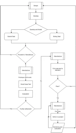
Figure 3. High level overview flowchart of the method used.
4. End target of modeling and implementation
respectfully, the air leakage rate for all air-conditioned buildings should not exceed 1.6 L/m2.s and 8.0 L/m2.s for all non-air-conditioned building [7].
In the static pressure test a constant pressure of the greater magnitude between 300 Pa and 0.3 Ws (where Ws is the designed wind pressure) will be used with water sprayed to the external face of not less than 0.05 L/m2s. The first 5 minutes will be water sprayed with zero applied pressure, then 15 minutes of water sprayed with the applied pressure then a final 5 minutes of water sprayed without the applied pressure, during this time observations are to be made from the internal face and any water ingress and damage is to be recorded.
Finally there is also a dynamic pressure test in which is to be performed after successful completion of the static pressure test. In each stage the pressure cycles between designated pressures which are increasing [7].
5. Targeted modeling, implementation and evaluation
In modeling and implementing new waterproof seals much can be learnt from the challenges encountered in creating past solutions and focus can be directed to these areas.
Experts with considerable experience in facades note that there are a number of weak areas and conditions which should be kept in mind [6]. Some of the most prominent points of interests to consider have found to be as follows: the joints between the walls and floor, deformation of the building because of applied and dead loads, manufacturing, production and assembly related tolerances, dynamic, horizontal floor displacements caused by wind pressure/suction or seismic actions, changes of length due to differing materials and temperatures and finally water penetration through wind driven rain causing pressure on the surface where surface tension and capillary effected water seeps through narrow joints [8]. These areas will be particularly considered in the modeling and implementation of the new sealing solution.
The full possible design criteria for waterproof and weatherproof seals and their influencing factors are needed to be considered and key relevant criteria to be checked against when modeling, implementing and evaluating a new sealing solution specific for use in panelized and modular forms of construction.
External conditions; UV radiation - leading to potential change in colour over time and potential change of stiffness over time, Temperature and temperature change - not to degrade under heat and not to change shape under heat, Humidity and humidity change, Rainfall, Wind pressure, Combined action of wind and rain (wind driven rain), Potential dust, dirt and grime, Chemical resistance -Air pollution and cleaning products.
Internal conditions; Suction pressure, Temperature (condensation risk), Air tightness (not permeable to air), Water tightness (not permeable to water), Ability to relieve vapour pressure, Sound transmission - Airborne sound and Structure-borne sounds.
Interaction between External and Internal conditions; Pressure and suction pressure combination, Tolerances – Production, Erection/Assembly, Deflection of components, Bowing, Creep, Tolerance stack up (the sum of tolerances), Allow air to enter/escape (ventilation), Prevent the condensation of water, Capillary water movement, Allow for differential movements -Deflections before, during and after installation, Long term creep, Dynamic movements, Expansion and shrinkage movements, Horizontal and vertical joints and their movements externally with their relation internally and vice-versa, Force transfer - element by element and supporting construction element, Allow drainage of runoff and infiltrated water, Allow/block passage of light and protection against frost damage (non-absorbing material).
of installation, Service life of the building - Design life, Maintenance required and ease of maintenance and susceptibility to insect and bird attack
6. Manufacturing Process Used
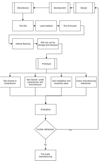
Figure 4. The manufacturing (and assembly) process.
7. Material Models
The surface of and the method to permanently fix a gasket or other solution to weatherproofing to the structure of the wall panel or module needs to be considered just as much as any other surface to the seal. Generally an attachment such as a seal particularly a gasket can be affixed through method of adhesions thus the relevant codes have been found to be: ASTM-D897 (2016) – Standard Test Method for Tensile Properties of Adhesive Bonds, BS EN-15870 (2009) (also the same as ISO-6922) – Adhesives. Determination of tensile strength of butt joints and ASTM-C907 (2017) – Standard Test Method for Tensile Adhesive Strength of Preformed Tape Sealants by Disk Method.
Finally gasket type seals and in seals in general which require friction to operate or may encounter friction during assembly, thus the relevant codes have been found to be: ASTM-D1894 (2014) – Standard Test Method for Static and Kinetic Coefficients of Friction of Plastic Film and Sheeting (ISO-15359 (1999)Horizontal Plane Method).
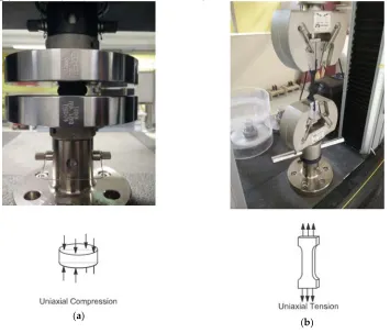
(a) (b)
Figure 5. Material testing of EPDM rubber used for Gasket: (a) Uniaxial Compression; (b) Uniaxial Tension
7.1 Hyperelastic Material Model
A constitutive model for an ideal elastic material is known as a Hyperelastic material model which has a stress-strain relationship based from strain deformation energy. Rubber is a typical prime example of suitable material to be modelled in this way as it is defined as non-linear elastic, isotropic and its behaviour is largely independent to strain rate. [9]. The identifying characteristics of hyperelastic materials are: significant elongation under and loading, minimal to no permanent deformation of the material after loading, non-linear relationship between force of the load and the stress and finally the internal energy can be used to describe the stress in the material [10]. Hyperelastic material models provide the means to model materials with this behaviour through using a strain energy density function [11].
7.2 Neo-Hookean Model
uniaxial test was carried out for tension and compression of this particular composition of EPDM rubber due to a reasonable understanding on how the material is expected to behave. In circumstances where only uniaxial test data is available a Neo-Hookean model is widely recommended to be used and thus it is the chosen model for this project [12].
The Neo-Hookean model can be useful in prediction of behaviour of elastomers and assumes perfect elasticity through the stages of deformation and can capture non-linear stress-strain relationship. However due to the fact that polymer chains under stress can initially move relative to each other but at a certain stage covalent cross links limit this and hence in turn increased the elastic modulus at this stage, the results is that the Neo-Hookean model is best suited for strains below this level [13].
The Neo-Hookean hyperelastic strain energy function comes in many forms. In ANSYS (2016) which was used for this project the hyperelastic strain-energy function which was used is as per Equation 1 below.
𝑊 =
𝜇
2
(𝐼 − 3) +
1
𝑑
( 𝐽 − 1 )
(1)
Where,
μ = initial shear modulus of materials d = material incompressibility parameter
K = initial bulk modulus which is related to the material incompressibility parameter by, 𝐾 =
After preparing the EPDM samples, testing was done on 5 specimens for each test, the average values were used as inputs to the Neo-Hookean material model which ANSYS (2016) calculated and fitted the curve, the results are as shown in figure 6. The close fit with the experimental data indicated that the Neo-Hookean would suffice, however if a close fit was not found it was planned to do other testing such as biaxial or shear and use a higher level material model such as Mooney-Rivlin model however in this case only uniaxial test data together with the Neo-Hookean model sufficed.
Figure 6. EPDM material - Neo-Hookean hyperelastic model fitted to uniaxial experimental data
7.3 Finite Element Model
Simulation comprises two stages. Firstly, stage one, the seal is compressed in the y direction. Secondly stage two, a fluid pressure is applied from the left side of the seal in figure 7.
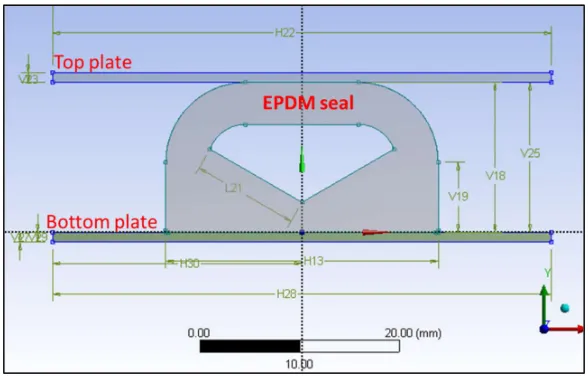
Figure 7. Geometry of the gasket seal before compression (Stage 1: Compression, Stage 2: Water Pressure).
The aluminium extrusion is modelled simply as rectangular element as seen at top and bottom plates in Figure 8. The gap is initially 15mm to match the dimension of the uncompressed seal, it is then reduced to 10mm. This is done by a gradual displacement of the top plate until it moved 5mm in the negative y direction. Next an increasing water pressure is applied on the left hand surface until the seal fails due to separation.
7.4 Assumptions/Simulation setup
The following assumptions and factors was used in the simulation setup:
Non-linear static analysis with direct solver.
Symmetric, Normal Lagrange contacts.
The only mode of failure assumed is the separation between EPDM seal and top plate.
Material assumed fully impermeable to fluids.
Negligible deformation of top and bottom plates.
Plane strain condition initially assumed. This assumption is investigated, the result is a larger material stiffness compared to plane stress as the material is not allowed to deform out of plane.
A friction factor of 0.1 between top plate and EPDM rubber. This assumption is investigated through a sensitivity analysis, the result is that overall sealing performance is not primarily sensitive to friction.
7.5 Deformation Analysis and Verification of Stage One
The FEA solution is verified for the deflection analysis before fluid pressures are applied in stage two. This includes examining the mesh, the plane strain assumption, and friction properties.
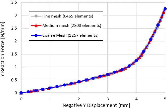
Figure 8. Y reaction force vs Negative Y displacement for three different mesh configuration.
(a)
(c)
Figure 9. Geometry of the gasket seal after compression for identical loading cases: (a) Mesh A; (b) Mesh B; (c) Mesh C.
There is minimal difference in the solution between the mesh configurations. The medium mesh is selected for this project. For fluid pressure penetration cases, the medium mesh is further refined at the location of initial separation to better predict fluid penetration in this key region.
7.6 Plane Strain Assumption
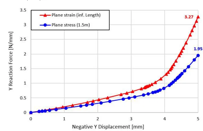
A key assumption in the analysis is the plane strain assumption, which restricts any deformation (strain) out of plane. Under plane strain, the seal is assumed to extend over a long length of the façade. The plane strain assumption increases the effective stiffness of the material in-plane, which may result in a larger force required to achieve a -5mm displacement as shown in figure 10.
To assess the impact of this assumption, two cases are simulated and are presented in figure 11: 1) Plane strain (infinite length)
2) Plane stress (1.5m)
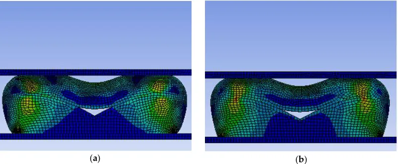
(a) (b)
Figure 11. Contour plot of equivalent stress for simulations: (a) Plane Stress Assumption; (b) Plane Strain Assumption.
As expected, the plane stress assumption resulted in lower vertical load required to achieve a displacement of -5mm (1.95N/mm vs 3.27N/mm). The difference in loading between the plane strain and plane stress assumption is significant (40%).
Hence, for a conservative prediction, the following assumptions are used:
When predicting required vertical loading, use the plane strain assumption.
When testing waterproof performance with fluid penetrating pressure, use the plane stress assumption (This case is critical due to smaller contact area and contact pressure between the seal and top plate).
7.7 Frictional Effects
The friction coefficient (COF) of the EPDM seal and plate was not experimentally measured and is therefore unknown in this study. Studies in the literature suggest that the COF between a dry EPDM rubber and steel plate can be anywhere between 0.5 – 2.5 depending on multiple factors [15]. However, the COF may take lower values under wet conditions, or if lubrication is used for installing the seal.
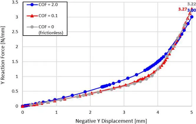
To address this uncertainty, a number of simulations are performed with different friction values between the EPDM seal and plate. In all cases, the friction between EPDM and EPDM is assumed to be 0.1. The sensitivity of the results to each case are show in figure 12.
Three friction cases are considered: 1) Frictionless, COF = 0
Figure 12. Effect of surface friction on vertical reaction force for multiple displacements.
7.8 Fluid Pressure Penetration - Stage Two
The second stage of the simulation involves applying a fluid pressure of increasing magnitude from one side of the seal. In this stage, a plane stress simulation is performed with a small COF =0.1. The effect of modelling parameters on the pressure simulation are shown below.
The results from figure 13 show that the maximum fluid pressure depends on the friction value between the seal and top plate. A lower COF resulted in lower maximum fluid pressure.
Figure 13. Effect of modelling parameters on results
Figure 13 shows the performance of the rubber seal with increased fluid pressure. The y-axis represents the reaction force or the top façade from the rubber seal. A value of zero on the y-axis indicates that the seal has fully separated from the top plate, allowing for fluid to leak through.
along the seal. Achieving a displacement of -5mm would require a compressive force of up to 3.3 N per mm of seal length, this value needs to be verified with actual testing.
For the purpose of façade applications, the codes specify a maximum fluid pressure of 2.3kPa. The results show that this criterion is met for all deflection values from -1 to -5mm as shown in figure 14.
Figure 14. Waterproof performance of EPDM seal for a variety vertical displacement. Plane stress (1.5m), COF
= 0.1
7.9 Finite Element Summary
Using a non-linear FEA with a hyperelastic material, the performance of the EPDM rubber was tested in two stages. First, the seal is compressed vertically be -5mm. Second, a penetrating fluid pressure is applied to one side of the seal.
The only mode of failure assumed is the separation of the EPDM seal at the top plate. The bonded contact with the bottom plate remains intact for all cases.
Under conservative assumptions (plane stress, frictionless contact) the FEA results suggest that the EPDM seal can adequately resist a constant fluid pressure of 2.3kPa.
Limitations of the current mainly constitute uncertainty in modelling parameters, including the material model, plane stress/strain assumption, and friction coefficient. To address this, sensitivity studies were performed to assess the impact of these parameters on the final results. Additional testing would provide confidence in the numerical accuracy of the results.
8. Water pressure testing
Tests for water penetration for varying compressions and pressures were carried out to understand the effect of tolerances in determining the robustness of the solution along with understanding the maximal sealing capacity.
Figure 15a shows the EPDM rubber gasket seal adhered to aluminium strip via tape adhesive and then sandwiched to the desired compression via the use of packers for measurement. Figure 15b shows a rubber boot seal is applied to the surface of the adjoined panel with waterproof silicone between the two members, this is then compressed and held tightly via screwed timber batons.
(a) (b)
Figure 15. Gasket Seal Water Penetration Testing (a) EPDM rubber gasket seal between testing panels; (b) A rubber boot seal to distribute water pressure to the gasket.
Tests were conducted on a pass/fail basis, pass being no observation of water ingress from the underside of the seal after 5 minutes of applied pressure and fail being the visibility of water ingress. At the design gap of 10mm the gasket which has a depth of 15mm is compressed 5mm, the performance of the gasket in creating a water right seal cannot be faulted. At none of the increasing water pressure from 0m of head to 2.8m of head (27.5 KPa equivalent) did water penetration occur, this extremely positive result was in line with the finite element prediction as it well exceeded the 300 Pa minimum or 0.3 Ws (where Ws is the designed wind pressure) requirement by AS4284: Testing of Building Facades.
For robustness and fuller understanding this test was repeated on several developed samples of varying compression. The aim in doing these extra tests was to encapsulate the expected building tolerances which may be experienced onsite and to help further verify and validate the finite element model. Values between 2-3mm either side of a 10mm gap accounted for the tolerances were developed from material irregularities and manufacturing limitations. The tests on these panels with a gap width of 11mm, 12mm, 13mm and 14mm resulted in all but the final scenario with a compression of 1mm reaching the maximum pressure available for testing of 2.8m of head (27.5KPa) without any sign of water penetration which is also in keeping with the finite elements predictions. The observation in the one configuration which water leakage was observed to occur (14mm gap which is equivalent of 1mm compression) was moisture build up and eventual droplet formation on the unadhered side of the gasket as expected.
9. Implementation
(a) (b)
Figure 16. Implementation with panelised form of prefabricated construction: (a) Commercial office building using the gasket seals; (b) EPDM gasket seal positions on the wall towards the outside face.
The completed prefabricated wall panels are lifted and place into position whilst compressing the rubber gasket as shown in figure 17a. The sealed joint after the completed lift and installation of the panel is shown figure 17b.
(a)
(b)
Figure 17. Lifting and placement of panels: (a) Complete prefabricated wall panels are lifted and place into position whilst compressing the rubber gasket; (b) Due diligence in measurement of gap width and assessment of shape and embedment depth
10. Monitoring and Evaluation
The monitoring and evaluation of the seal once it was fully implemented and adopted for the case study project verified that at least in the short term that this is an appropriate solution which satisfies the design requirements. Figure 17b shows the due diligence taken in measurement of gap width between panels to compare with expected building tolerances and its compatibility with the seals required range of compression for adequate function. Additionally, assessment of the shape and condition of the seal from the external face along with the embedment depth along the height was noted.
rain (wind driven rain), notable sound transmission - airborne sound and structure-borne sounds, , potential dust, dirt and grim buildup, chemical resistance against air pollution and cleaning products, allowance for tolerances (production, erection/assembly) , deflection of components to bowing, allowance for drainage of runoff and infiltrated water and any damage during installation and/or transport. The result of the inspection and the open dialogue with the building occupants have led to confirmation of the performance of the gasket as a robust weather proofing solution meeting the aforementioned design criteria.
As monitoring and evaluation is a continual cycle as previously shown in figure 5 the process is not over at any stage during the life of the building. There are some identified design objectives which can only be fully assured satisfactory attainment only after a long period of time, these include damage due to long term UV radiation which may lead to potential change in colour over time and potential change of stiffness over time, temperature and temperature change which may lead to the degradation of the rubber over time, humidity and change of humidity causing condensation and potential mould growth behind the seal, the effects of creep on the seal, differential movement of the foundation and its effect. These design objectives were not able to be evaluated at the current stage due to their primary potential presence in the long term such as long term UV exposure and due to difficulties in capturing the required information to be able to confidently mark successful satisfaction of design criteria for example difficulty to get in behind the seal or behind the inside face of the wall to check for potential mould growth.
11. Conclusions
A purpose specific weatherproof seal in the form of a EPDM rubber gasket has been presented for prefabricated panelised and modular systems and a full finite element analysis has been conducted on the compression of the gasket obtaining the stress profile and opposing reaction force necessary for levels of compression then fluid dynamic computation has then been carried out of the compressed seal with an increasing water pressure on one side of the seal until the reactionary force of the seal reduces to zero indicating the penetration of water. The manufacturing process used to bring the final design of the gasket into reality has been detailed and outlined as a flow chat, the implementation of the gasket seal in a real world scenario has been successfully carried out through its full use in a case study project with the assembly of the seal on the prefabricated panels offsite and the installation of the panels on site which successfully achieved the goal of implementing a waterproofing solution between prefabricated elements without any onsite installation and finally a short to medium term monitoring and evaluation was carried out which validated the real world practical effectiveness of the gasket seal for waterproofing of vertical joints in prefabricated construction between each respected fully completed panel.
References
1. EMSEAL, Expansion Joints and Pre-Compressed Sealants. EMSEAL LLC. 111 Royal Group Crescent Woodbridge, ON L4H 1X9 Canada, 2018.
2. Lu, N. The current use of offsite construction techniques in the United States construction industry. in
Construction Research Congress 2009: Building a Sustainable Future. 2009.
3. NHBC, Modern methods of construction. Views from the industry, 2016. NHBC House Davy Avenue Knowlhill Milton Keynes MK5 8FP.
4. Gibb, A.G., Standardization and pre-assembly-distinguishing myth from reality using case study research.
Construction Management & Economics, 2001. 19(3): p. 307-315.
5. Lopez, D. and T.M. Froese, Analysis of Costs and Benefits of Panelized and Modular Prefabricated Homes.
Procedia Engineering, 2016. 145: p. 1291-1297.
6. Herzog, T., R. Krippner, and W. Lang, Facade Construction Manual. 2012. 7. AS4284, AS 4284:2008 Testing of Building Facades. Standards Australia, 2008. 8. Schwartz, T.A. Water in exterior building walls: problems and solutions. 1991. ASTM.
9. Iveta, G. and B. Jozef, Hyperplastic material models and their applications in engineering. Applied Mechanics & Materials, 2014(611).
10. Ficková, M., et al., STROJÍRENSKÁ TECHNOLOGIE. 2013.
11. Ogden, R.W., Non-linear elastic deformations. 1997: Courier Corporation.
12. ABAQUS, ABAQUS Benchmarks Manual. Version 6.6 Documentation, ABAQUS Inc., 2006.
13. Gent, A.N., Engineering with rubber: how to design rubber components. 2012: Carl Hanser Verlag GmbH Co KG.
14. ANSYS, Release 17.2. ANSYS AIM™, 2016.
![Figure 1. Gasket and jointing element sealing principles [6].](https://thumb-us.123doks.com/thumbv2/123dok_us/7977740.1322964/2.612.172.459.559.679/figure-gasket-jointing-element-sealing-principles.webp)